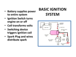
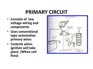
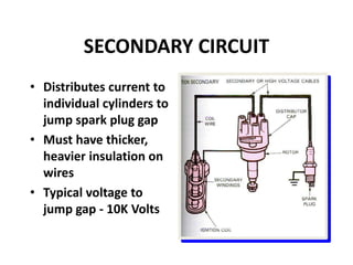
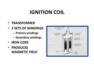
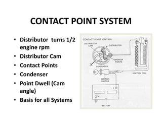
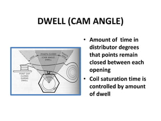
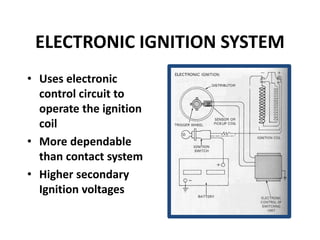
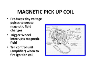
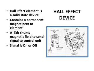
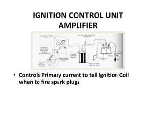
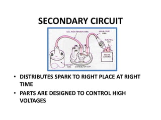
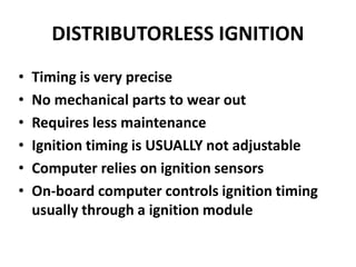
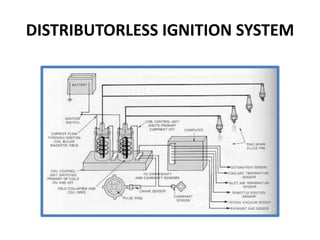
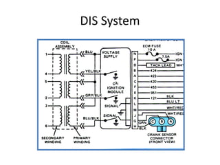
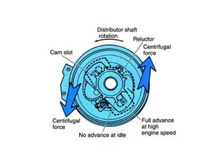
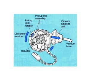
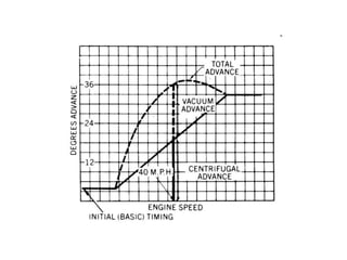
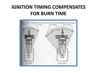
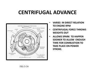
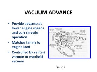
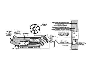
MODULE II
Ignition Systems
IGNITION FUNCTION
• Produces 30,000 volt spark across spark plug
• Distributes high voltage spark to each spark
plug in correct sequence
• Times the spark so it occurs as piston is
nearing top dead center
• Varies spark timing with load, speed, and
other conditions
BASIC IGNITION SYSTEM
COMPONENTS
• BATTERY
• IGNITION SWITCH
• IGNITION COIL
• SWITCHING DEVICE
• SPARK PLUG
• IGNITION SYSTEM WIRES
BASIC IGNITION
SYSTEM
• Battery supplies power
to entire system
• Ignition Switch turns
engine on or off
• Coil transforms volts
• Switching device
triggers ignition coil
• Spark Plug and wires
distribute spark
PRIMARY CIRCUIT
• Consists of low
voltage wiring and
components
• Uses conventional
type automotive
primary wires
• Controls when
ignition will take
place. (When coil
fires)
SECONDARY CIRCUIT
• Distributes current to
individual cylinders to
jump spark plug gap
• Must have thicker,
heavier insulation on
wires
• Typical voltage to
jump gap - 10K Volts
IGNITION COIL
• TRANSFORMER
• 2 SETS OF WINDINGS
– Primary windings
– Secondary windings
• IRON CORE
• PRODUCES
MAGNETIC FIELD
IGNITION SYSTEM TYPES
• CONTACT POINT IGNITION SYSTEM
• ELECTRONIC IGNITION SYSTEM
• DISTRIBUTORLESS IGNITION SYSTEM
CONTACT POINT SYSTEM
• Distributor turns 1/2
engine rpm
• Distributor Cam
• Contact Points
• Condenser
• Point Dwell (Cam
angle)
• Basis for all Systems
DWELL (CAM ANGLE)
• Amount of time in
distributor degrees
that points remain
closed between each
opening
• Coil saturation time is
controlled by amount
of dwell
ELECTRONIC IGNITION SYSTEM
• Uses electronic
control circuit to
operate the ignition
coil
• More dependable
than contact system
• Higher secondary
Ignition voltages
MAGNETIC PICK UP COIL
• Produces tiny voltage
pulses to create
magnetic field
changes
• Trigger Wheel
interrupts magnetic
field
• Tell control unit
(amplifier) when to
fire ignition coil
HALL EFFECT
DEVICE
• Hall Effect element is
a solid state device
• Contains a permanent
magnet next to
element
• A Tab shunts
magnetic field to send
signal to control unit
• Signal is On or Off
IGNITION CONTROL UNIT
AMPLIFIER
• Controls Primary current to tell Ignition Coil
when to fire spark plugs
HIGH VOLTAGE SECONDARY
COMPONENTS
• IGNITION COIL
• COIL WIRE
• DISTRIBUTOR
• DISTRIBUTOR CAP
• DISTRIBUTOR ROTOR
• SPARK PLUG WIRE
• SPARK PLUG
SECONDARY CIRCUIT
• DISTRIBUTES SPARK TO RIGHT PLACE AT RIGHT
TIME
• PARTS ARE DESIGNED TO CONTROL HIGH
VOLTAGES
SPARK PLUGS
Pg 121C
1 2 3 4
7
5
6 8 9 10
1.Normal
2.Overheated
3.Pre-ignition
4.Cracked
insulator
5.Bridged gap
6.Deposit
fouled
7.Carbon
glazed
8.Splashed
9.Glazed
10. Oil fouled
SPARK PLUG TYPES
DISTRIBUTORLESS IGNITION
• Timing is very precise
• No mechanical parts to wear out
• Requires less maintenance
• Ignition timing is USUALLY not adjustable
• Computer relies on ignition sensors
• On-board computer controls ignition timing
usually through a ignition module
DISTRIBUTORLESS IGNITION SYSTEM
DIS System
IGNITION TIMING FACTORS
• Ignition timing is how early or late spark
plugs fire in relation to position of engine
pistons
• Ignition timing must vary with engine speed,
load and temperature
• Must be advanced at times and retarded at
other times
METHODS OF IGNITION TIMING
• DISTRIBUTOR CENTRIFUGAL ADVANCE
• DISTRIBUTOR VACUUM ADVANCE
• ELECTRONIC (COMPUTER) ADVANCE
IGNITION TIMING COMPENSATES
FOR BURN TIME
CENTRIFUGAL ADVANCE
• VARIES IN DIRECT RELATION
TO ENGINE RPM
• CENTRIFUGAL FORCE THROWS
WEIGHTS OUT
• ALLOWS SPARK TO HAPPEN
SOONER TO ALLOW ENOUGH
TIME FOR COMBUSTION TO
TAKE PLACE ON POWER
STROKE.
FIG 5-34
VACUUM ADVANCE
• Provide advance at
lower engine speeds
and part throttle
operation
• Matches timing to
engine load
• Controlled by venturi
vacuum or manifold
vacuum
FIG 5-35
ELECTRONIC SPARK TIMING
• Distributor does not have a centrifugal or
vacuum advance mechanism
• Uses engine sensors as inputs to computer
• You must disable spark advance when setting
base timing on computer controlled cars
ENGINE FIRING
ORDER
• REFERS TO SEQUENCE
SPARK PLUGS FIRE
• CAST INTO INTAKE
MANIFOLD
• EACH ENGINE WILL HAVE
DIFFERENT FIRING ORDER
• MUST USE DURING
TUNE-UP
FIG 5-3

Ignition systems

  • 1.
  • 2.
  • 3.
    IGNITION FUNCTION • Produces30,000 volt spark across spark plug • Distributes high voltage spark to each spark plug in correct sequence • Times the spark so it occurs as piston is nearing top dead center • Varies spark timing with load, speed, and other conditions
  • 4.
    BASIC IGNITION SYSTEM COMPONENTS •BATTERY • IGNITION SWITCH • IGNITION COIL • SWITCHING DEVICE • SPARK PLUG • IGNITION SYSTEM WIRES
  • 5.
    BASIC IGNITION SYSTEM • Batterysupplies power to entire system • Ignition Switch turns engine on or off • Coil transforms volts • Switching device triggers ignition coil • Spark Plug and wires distribute spark
  • 6.
    PRIMARY CIRCUIT • Consistsof low voltage wiring and components • Uses conventional type automotive primary wires • Controls when ignition will take place. (When coil fires)
  • 7.
    SECONDARY CIRCUIT • Distributescurrent to individual cylinders to jump spark plug gap • Must have thicker, heavier insulation on wires • Typical voltage to jump gap - 10K Volts
  • 8.
    IGNITION COIL • TRANSFORMER •2 SETS OF WINDINGS – Primary windings – Secondary windings • IRON CORE • PRODUCES MAGNETIC FIELD
  • 9.
    IGNITION SYSTEM TYPES •CONTACT POINT IGNITION SYSTEM • ELECTRONIC IGNITION SYSTEM • DISTRIBUTORLESS IGNITION SYSTEM
  • 10.
    CONTACT POINT SYSTEM •Distributor turns 1/2 engine rpm • Distributor Cam • Contact Points • Condenser • Point Dwell (Cam angle) • Basis for all Systems
  • 11.
    DWELL (CAM ANGLE) •Amount of time in distributor degrees that points remain closed between each opening • Coil saturation time is controlled by amount of dwell
  • 12.
    ELECTRONIC IGNITION SYSTEM •Uses electronic control circuit to operate the ignition coil • More dependable than contact system • Higher secondary Ignition voltages
  • 13.
    MAGNETIC PICK UPCOIL • Produces tiny voltage pulses to create magnetic field changes • Trigger Wheel interrupts magnetic field • Tell control unit (amplifier) when to fire ignition coil
  • 14.
    HALL EFFECT DEVICE • HallEffect element is a solid state device • Contains a permanent magnet next to element • A Tab shunts magnetic field to send signal to control unit • Signal is On or Off
  • 15.
    IGNITION CONTROL UNIT AMPLIFIER •Controls Primary current to tell Ignition Coil when to fire spark plugs
  • 16.
    HIGH VOLTAGE SECONDARY COMPONENTS •IGNITION COIL • COIL WIRE • DISTRIBUTOR • DISTRIBUTOR CAP • DISTRIBUTOR ROTOR • SPARK PLUG WIRE • SPARK PLUG
  • 17.
    SECONDARY CIRCUIT • DISTRIBUTESSPARK TO RIGHT PLACE AT RIGHT TIME • PARTS ARE DESIGNED TO CONTROL HIGH VOLTAGES
  • 18.
  • 19.
    1 2 34 7 5 6 8 9 10 1.Normal 2.Overheated 3.Pre-ignition 4.Cracked insulator 5.Bridged gap 6.Deposit fouled 7.Carbon glazed 8.Splashed 9.Glazed 10. Oil fouled
  • 20.
  • 21.
    DISTRIBUTORLESS IGNITION • Timingis very precise • No mechanical parts to wear out • Requires less maintenance • Ignition timing is USUALLY not adjustable • Computer relies on ignition sensors • On-board computer controls ignition timing usually through a ignition module
  • 22.
  • 23.
  • 24.
    IGNITION TIMING FACTORS •Ignition timing is how early or late spark plugs fire in relation to position of engine pistons • Ignition timing must vary with engine speed, load and temperature • Must be advanced at times and retarded at other times
  • 25.
    METHODS OF IGNITIONTIMING • DISTRIBUTOR CENTRIFUGAL ADVANCE • DISTRIBUTOR VACUUM ADVANCE • ELECTRONIC (COMPUTER) ADVANCE
  • 29.
  • 30.
    CENTRIFUGAL ADVANCE • VARIESIN DIRECT RELATION TO ENGINE RPM • CENTRIFUGAL FORCE THROWS WEIGHTS OUT • ALLOWS SPARK TO HAPPEN SOONER TO ALLOW ENOUGH TIME FOR COMBUSTION TO TAKE PLACE ON POWER STROKE. FIG 5-34
  • 31.
    VACUUM ADVANCE • Provideadvance at lower engine speeds and part throttle operation • Matches timing to engine load • Controlled by venturi vacuum or manifold vacuum FIG 5-35
  • 32.
    ELECTRONIC SPARK TIMING •Distributor does not have a centrifugal or vacuum advance mechanism • Uses engine sensors as inputs to computer • You must disable spark advance when setting base timing on computer controlled cars
  • 34.
    ENGINE FIRING ORDER • REFERSTO SEQUENCE SPARK PLUGS FIRE • CAST INTO INTAKE MANIFOLD • EACH ENGINE WILL HAVE DIFFERENT FIRING ORDER • MUST USE DURING TUNE-UP FIG 5-3