The document discusses ignition systems for spark-ignition engines. It covers the functions of the ignition system including initiating combustion through an electric spark. It describes the components involved like the ignition coil, spark plugs, and distributor. It discusses requirements for reliable ignition like providing enough ignition energy even under unfavorable conditions. It also covers ignition timing and how it is optimized based on factors like engine speed and load.
This presentation is all about how ignition system works in petrol as well as in diesel engines. how we can improve its mechanical as well as volumetric efficiency. How we can gain more output at lesser input.
This presentation is all about how ignition system works in petrol as well as in diesel engines. how we can improve its mechanical as well as volumetric efficiency. How we can gain more output at lesser input.
Now a day’s power generation is most important for
every country. This power is generated by some thermal
cycles. But single cycle cannot be attain complete power
requirements and its efficiency also very low so that to fulfill
this requirements to combine two or more cycles in a single
power plant then we can increase the efficiency of the power
plant. Its increased efficiency is more than that of if the plant
operated on single cycle. In which we are using two different
cycles and these two cycles are operated by means of different
working mediums. These type of power plants we can called
them like combined cycle power plants. In combined cycle
power plants above cycle is known as topping cycle and below
cycle is known as bottoming cycle. The above cycle generally
brayton cycle which uses air as a working medium. When the
power generation was completed the exhaust gas will passes
in to the waste heat recovery boiler. Another cycle also
involved in bottoming cycle. This cycle works on the basis on
rankine cycle. In which steam is used as working medium.
The main component in bottoming cycle is waste heat
recovery boiler. It will receive exhaust heat from the gas
turbine and converts water in to steam. The steam used for
generating power by expansion on steam turbine. Combined
cycle power plants are mostly used in commercial power
plants.
In this paper we are analyzing one practical
combined cycle power plant. In practical conditions due to
some losses it can not be generates complete power. So that
we are invistigated why it is not give that much of power and
the effect of various operating parameters such as maximum
temperature and pressure of rankine cycle, gas turbine inlet
temperature and pressure ratio of Brayton cycle on the net
output work and thermal efficiency of the combine cycle
power plant.
The outcome of this work can be utilized in order to
facilitate the design of a combined cycle with higher efficiency
and output work. Mathematical calculations and simple
graphs in ms excel, and auto cad has been carried out to
study the effects and influences of the above mentioned
parameters on the efficiency and work output.
Multi spark ignition system has proved their potential
in improving the performance of the engines and
improved emissive characteristics as compared with
the single spark plug ignition system. Recently a new
type engine has been introduced which uses triple
spark plugs at different location, controlled by an
advanced electronic control unit. Experiments were
conducted at different load conditions and different
types of engines has proved that multi spark plug
ignition engines are surely better than a single spark
plug engine
Ignition system of an automobile is one of the most important system, as it gives necessary energy to the fuel for combustion. Depending on the electric energy supplied to the spark plug, ignition system is divided into two main types. They are namely inductive ignition and capacitor discharge ignition (CDI). Both the ignition types perform the same operation, but the difference is supply of electrical energy to the spark plug.
Abstract: A low-cost high-performance fuel cell inverter for nominal 48 V dc to 120 V ac conversion is described. The inverter topology eliminates the need for a dc intermediate voltage by using an ac-link output inverter. The design minimizes overall system cost – including energy storage and management. The design provides low-ripple current-controlled interfacing to the fuel-cell stack, an intermediate-voltage battery energy storage buffer, and an ac-link output inverter. The circuit is based on square-wave cycloconverter technology, combined with a simple approach modulation process. Number of stages and magnetic elements low while providing galvanic isolation. Either SCRs or IGBTs can be used as output devices, which provides an unusual cost/performance trade-off possibility. Gate drives and other control elements are also simplified. The design provides excellent performance with a minimum of filter components and a simple control.
Test Rig for Measurement of Spark Advance Angle and Ignition System Using AT8...IJSRD
An electronic ignition control system for internal combustion engine, notably for motor vehicles, which comprises a rotary member revolving at engine speed and provided with two reference marks Which the position correspond to the maximum ignition advance angle and to the minimum ignition advance angle, respectively , said reference marks defining at least one area on said rotary member, a sensor disposed in close vicinity of said rotary member so as to detect the moments of passage of said references marks and at least one up and down counter for counting pulse, said rotary member further comprising a third references marks separate from the first two reference marks aforesaid so as to define two successive areas scanned in succession by said sensor, while a first up and down counter positively counts the pulse from a first area and negatively counts, during passage of second area the pulse from second clock system adapted to emit pluses at a frequency programmable according to the desired ignition advance law, the resetting of said up and down counter being utilized for producing ignition spark. Finally up and down counter calculates the final value of the advance angle. After calculating the final value of advance angle signal send to the ignition box to ignition coil, and ignition coil operate the spark as per advance angle.
Vehicle body design and materials, types of passenger vehicle body design and types , commercial vehicle body design and its types ,Automotive engineering
Explore the innovative world of trenchless pipe repair with our comprehensive guide, "The Benefits and Techniques of Trenchless Pipe Repair." This document delves into the modern methods of repairing underground pipes without the need for extensive excavation, highlighting the numerous advantages and the latest techniques used in the industry.
Learn about the cost savings, reduced environmental impact, and minimal disruption associated with trenchless technology. Discover detailed explanations of popular techniques such as pipe bursting, cured-in-place pipe (CIPP) lining, and directional drilling. Understand how these methods can be applied to various types of infrastructure, from residential plumbing to large-scale municipal systems.
Ideal for homeowners, contractors, engineers, and anyone interested in modern plumbing solutions, this guide provides valuable insights into why trenchless pipe repair is becoming the preferred choice for pipe rehabilitation. Stay informed about the latest advancements and best practices in the field.
Sachpazis:Terzaghi Bearing Capacity Estimation in simple terms with Calculati...Dr.Costas Sachpazis
Terzaghi's soil bearing capacity theory, developed by Karl Terzaghi, is a fundamental principle in geotechnical engineering used to determine the bearing capacity of shallow foundations. This theory provides a method to calculate the ultimate bearing capacity of soil, which is the maximum load per unit area that the soil can support without undergoing shear failure. The Calculation HTML Code included.
Immunizing Image Classifiers Against Localized Adversary Attacksgerogepatton
This paper addresses the vulnerability of deep learning models, particularly convolutional neural networks
(CNN)s, to adversarial attacks and presents a proactive training technique designed to counter them. We
introduce a novel volumization algorithm, which transforms 2D images into 3D volumetric representations.
When combined with 3D convolution and deep curriculum learning optimization (CLO), itsignificantly improves
the immunity of models against localized universal attacks by up to 40%. We evaluate our proposed approach
using contemporary CNN architectures and the modified Canadian Institute for Advanced Research (CIFAR-10
and CIFAR-100) and ImageNet Large Scale Visual Recognition Challenge (ILSVRC12) datasets, showcasing
accuracy improvements over previous techniques. The results indicate that the combination of the volumetric
input and curriculum learning holds significant promise for mitigating adversarial attacks without necessitating
adversary training.
Overview of the fundamental roles in Hydropower generation and the components involved in wider Electrical Engineering.
This paper presents the design and construction of hydroelectric dams from the hydrologist’s survey of the valley before construction, all aspects and involved disciplines, fluid dynamics, structural engineering, generation and mains frequency regulation to the very transmission of power through the network in the United Kingdom.
Author: Robbie Edward Sayers
Collaborators and co editors: Charlie Sims and Connor Healey.
(C) 2024 Robbie E. Sayers
Final project report on grocery store management system..pdfKamal Acharya
In today’s fast-changing business environment, it’s extremely important to be able to respond to client needs in the most effective and timely manner. If your customers wish to see your business online and have instant access to your products or services.
Online Grocery Store is an e-commerce website, which retails various grocery products. This project allows viewing various products available enables registered users to purchase desired products instantly using Paytm, UPI payment processor (Instant Pay) and also can place order by using Cash on Delivery (Pay Later) option. This project provides an easy access to Administrators and Managers to view orders placed using Pay Later and Instant Pay options.
In order to develop an e-commerce website, a number of Technologies must be studied and understood. These include multi-tiered architecture, server and client-side scripting techniques, implementation technologies, programming language (such as PHP, HTML, CSS, JavaScript) and MySQL relational databases. This is a project with the objective to develop a basic website where a consumer is provided with a shopping cart website and also to know about the technologies used to develop such a website.
This document will discuss each of the underlying technologies to create and implement an e- commerce website.
Cosmetic shop management system project report.pdfKamal Acharya
Buying new cosmetic products is difficult. It can even be scary for those who have sensitive skin and are prone to skin trouble. The information needed to alleviate this problem is on the back of each product, but it's thought to interpret those ingredient lists unless you have a background in chemistry.
Instead of buying and hoping for the best, we can use data science to help us predict which products may be good fits for us. It includes various function programs to do the above mentioned tasks.
Data file handling has been effectively used in the program.
The automated cosmetic shop management system should deal with the automation of general workflow and administration process of the shop. The main processes of the system focus on customer's request where the system is able to search the most appropriate products and deliver it to the customers. It should help the employees to quickly identify the list of cosmetic product that have reached the minimum quantity and also keep a track of expired date for each cosmetic product. It should help the employees to find the rack number in which the product is placed.It is also Faster and more efficient way.
Saudi Arabia stands as a titan in the global energy landscape, renowned for its abundant oil and gas resources. It's the largest exporter of petroleum and holds some of the world's most significant reserves. Let's delve into the top 10 oil and gas projects shaping Saudi Arabia's energy future in 2024.
Top 10 Oil and Gas Projects in Saudi Arabia 2024.pdf
Ignition Engine working operation
1. Ignition
The ignition system's function is to initiate combustion in the flammable air-fuel
mixture by igniting it at precisely the right moment. In the spark-ignition (Otto) engine, this
is achieved with an electrical spark, i.e. an arc discharge between the spark plug's electrodes.
Consistently reliable ignition under all circumstances is essential for ensuring fault-free
catalytic-converter operation. Misfiring results in damage to or destruction of the catalytic
converter due to overheating during afterburning of the uncombusted mixture.
Mixture ignition
Provided the composition of the mixture is stoichiometric, energy of approximately
0.2 mJ is required for each individual ignition of the A/F mixture via electric spark. Over 3
mJ are required for a rich or lean mixture. This energy represents only a fraction of the total
energy in the ignition spark, the actual ignition energy. If sufficient ignition energy is not
available, there will be no ignition, the mixture cannot ignite, and misfiring will result.
The system must therefore deliver enough ignition energy to ensure consistently
reliable ignition of the mixture, even under unfavourable conditions. Igniting a small
flammable mixture cloud flowing past the spark can be enough to initiate the process. This
mixture cloud ignites, the flame spreads to the remaining mixture in the cylinder, and the fuel
starts to combust. Ignitability is enhanced by efficient fuel atomization and good access of the
mixture to the electrodes, as well as through extended spark duration and spark length (large
electrode gap).
The spark plug determines the location and length of the spark; spark duration
depends upon the type and design of the ignition system, as well as on the momentary
ignition conditions.
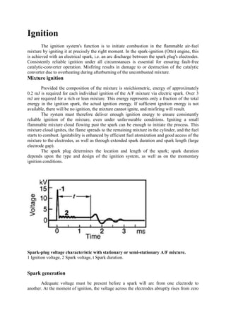
Spark-plug voltage characteristic with stationary or semi-stationary A/F mixture.
1 Ignition voltage, 2 Spark voltage, t Spark duration.
Spark generation
Adequate voltage must be present before a spark will arc from one electrode to
another. At the moment of ignition, the voltage across the electrodes abruptly rises from zero
2. up to the arcing (ignition) voltage and the plug fires. Once the spark has ignited the spark-
plug voltage drops to the sparking voltage. The A/F mixture may ignite at any point during
the firing period of the ignition spark (spark duration). Once the spark has broken away, the
voltage is damped and drops to zero.
Although intense mixture turbulence is basically desirable, it can extinguish the spark,
thus leading to incomplete combustion. The energy stored in the ignition coil should therefore
suffice for one or more consecutive sparks, depending on individual requirements.
High-voltage generation and energy storage
Battery-ignition systems generally employ an ignition coil to generate the high-
tension voltage needed to generate the spark. The ignition coil operates as an autotransformer
but within coil ignition systems it also assumes the further important function of storing the
ignition energy. When the contact breaker closes, energy from the vehicle's electrical system
flows into the coil's primary winding. This energy is then stored in a magnetic field until the
firing point, when the secondary winding discharges it to one of the engine's spark plugs. The
ignition coil is designed to ensure that the available high-tension voltage in the coil is always
well in excess of the spark plug's maximum possible ignition-voltage requirement. Energy
levels of 60...120 mJ within the coil correspond to an available voltage of 25...30 kV.
The operational reserves of high voltage and ignition energy are sufficient to
compensate for all electrical losses. Inadequate maintenance reduces these high-voltage
reserves, and leads to ignition and combustion miss. Engine power drops and fuel
consumption increases. In addition, this phenomenon can result in damage to or destruction
of the catalytic converter, should one be installed. In extreme cases, the engine either fails to
start – especially when cold – or stalls.
Ignition systems are also available with capacitive energy storage (CDI or Capacitor
Discharge Ignition) for use on high-performance and racing engines. These systems store the
ignition energy in the electrical field of a capacitor before a special transformer transmits it to
the spark plug in the form of a high-voltage ignition pulse.
Ignition timing and adjustment
Approximately two milliseconds elapse between the mixture's initial ignition and its
complete combustion. The ignition spark must therefore arc early enough to ensure that main
combustion, and thus the combustion-pressure peak in the cylinder, occur shortly after piston
TDC. The ignition angle should therefore move further in the advance direction along with
increasing engine speed. The chosen firing point should ensure that the following
requirements are met:
�Maximum engine performance
�Low fuel consumption
�No engine knock
�Clean exhaust gas.
Since it is impossible to obtain optimal compliance with all of these requirements
simultaneously; compromises must be found on a case-to-case basis. Optimal ignition timing
is defined according to a variety of parameters. The most important are engine speed, engine
load, engine design, fuel quality and momentary operating conditions (starting, idle and
trailing throttle, etc.). In the simplest case, spark-advance mechanisms sensitive to variations
in engine speed and intake-manifold vacuum adapt the ignition timing to suit the engine's
current operating conditions.
In modern engine-management systems with extended functions, additional
adjustments can be used e.g. for rapid torque adaptation or for swift heating of the catalytic
converter. All the adjustment strategies can operate either individually or simultaneously. The
3. degree to which the ignition timing is advanced or retarded is determined by the ignition-
advance curves calibrated specifically for each individual engine configuration.
At full load, the accelerator pedal is depressed fully and the throttle is wide open
(WOT). Along with increasing engine speeds, ignition takes place earlier in order to maintain
the combustion pressure at the levels required for optimal engine performance. The leaner
A/F mixtures encountered during part-throttle operation are more difficult to ignite. Because
this means that more time is required for ignition, it must be triggered earlier, with the timing
being shifted further in the "advance" direction.
The manifold vacuum employed to determine the necessary degree of spark advance
is monitored downstream from the throttle valve. If the vacuum bore is located near the
throttle valve (see Ignition systems), the vacuum initially increases as the throttle is opened
wider and begins to fall in the proximity of the full-throttle (WOT) position. The
progressively wider throttle openings required to increase engine speed on the operating
curve for part-throttle road operation are reflected in the relationship between vacuum and
min–1
shown in the diagram.
Example of cumulative ignition timing consisting of centrifugal and vacuum advance
1 Part-load operation, 2 Full load.
Yet another diagram shows the curves for combustion-chamber pressure in a 4-stroke
engine with correct and incorrect ignition timing. Even if the timing is initially correct,
neglected maintenance can allow it to drift over the course of time. If the timing shifts
towards a later firing point ("retard"), the result is a gradual drop in engine power and
4. increased fuel consumption. Excessive "advance" may result in extreme cases in serious
damage to spark plugs or to the engine if the engine knocks.
The level of exhaust emissions also increases.
Combustion-pressure curve for various ignition firing points
1 Correct ignition advance (Za),
2 Excessive ignition advance (Zb),
3 Excessive ignition retard (Zc).
Ignition and emissions
Owing to the fact that it directly affects the various exhaust-gas components, the
ignition has a significant effect upon exhaust emissions. Because various – and in this context
sometimes mutually antagonistic – factors such as fuel economy, driveability, etc., are also
potential optimization criteria, it is not always possible to specify the ideal ignition timing for
minimum emissions.
5. 1) Any desired ignition timing is not possible with EI. DLI therefore dominates with
integrated engine-management systems.
Shifts in ignition timing induce mutually inverse response patterns in fuel
consumption and exhaust emissions: While more spark advance increases power and reduces
fuel consumption, it also raises HC and, in particular, NOx emissions. Excessive spark
advance can cause engine knock and lead to engine damage. Retarded ignition results in
higher exhaust-gas temperatures, which can also harm the engine. Electronic engine-
management systems featuring programmed ignition curves are designed to adapt ignition
timing in response to variations in factors such as min–1, load, temperature, etc. They can
thus be employed to achieve the optimum compromise between these mutually antagonistic
objectives.
Ignition energy
The ignition system generates a high-voltage spark at the spark plug to initiate
combustion. A ignition-spark energy of approx. 0.2 mJ is adequate to ignite a stoichiometric
air-fuel mixture, while richer or leaner mixtures require substantially higher levels of spark
energy. Excess energy, i.e., from an ignition system designed to generate a high-energy spark
of extended duration (transistorized or electronic ignition) stabilizes flame propagation and
reduces the fluctuations from cycle to cycle.
The reduction in fluctuations results in smoother engine operation and lower HC
emissions. Increased spark projection, larger electrode gaps and thin electrodes also have a
positive influence on the engine's smoothness and HC emissions.
Ignition coil
The ignition coil functions as both an energy-storage device and a transformer. The
coil, which is powered by DC voltage from the vehicle's electrical system, supplies the
ignition pulses for the spark plugs at the required high voltage and discharge energy. The
ignition driver stage with its defined deactivation current combines with a primary winding
featuring specific resistance and inductance characteristics to determine the amount of energy
stored within the ignition coil's magnetic field. The secondary winding can be designed to
provide peak voltage, spark current and discharge duration in accordance with individual
requirements.
The contact-breaker points used with coil ignition (CI) can only handle interrupt
currents of up to approx. 5 A. TI, EI and DLI ignition systems and Motronic ECUs can
handle much higher interrupt currents. The series resistors generally employed with coil
ignition (they can be bypassed to increase energy during cold starts) can be omitted in
electronic ignition systems. Here the electronic circuitry activates the ignition coil depending
on battery voltage, engine speed and other influencing variables in such good time that full
energy is available at the ignition point.
Each ignition coil is designed to meet the requirements of a particular application. It
must charge quickly in order to furnish the voltages and ignition energies required at high
engine speeds. Important priorities thus include low primary inductance and, in some cases,
higher primary interrupt currents (for adequate energy storage).
6. Ignition coils (schematic)
Rotating distribution: a) Single-spark ignition coil. Distributorless ignition: b) Single-
spark ignition coil, c) Dual-spark ignition coil.
Design and operation
Traditional ignition coils with asphalt or oil insulation enclosed in metal casings are
being increasingly replaced by units featuring an epoxy-resin filler. These not only allow
more latitude in the selection of geometry, type and number of electrical terminals, but also
provide more compact dimensions, better vibration resistance and lower weight. The ignition
coil is generally attached by way of the iron core to the engine or vehicle body. Rod-type
ignition coils are installed in the cylinder-head recess above the spark plug.
The coil's synthetic materials provide good adhesion between all of the high-voltage
components and the molded epoxy resin, which penetrates into all the capillary spaces.
Supplementary iron cores are sometimes embedded on the inside of the synthetic molding.
The secondary winding is mostly designed as a disk or sandwich coil, with the windings
distributed among a series of segments. Even distribution of stresses among the insulating
elements in all chambers combines with high dielectric strength to permit compact
dimensions while at the same time making foil and paper between wire layers redundant. The
winding's self-capacitance is also reduced.
Because lower breakdown voltages are required for the negative (relative to engine
ground) ignition spark, the positive terminals for the primary and secondary windings are
generally combined on those ignition coils used with rotating high-voltage distribution.
Single and dual-spark ignition coils are an alternative for use in ignition systems with
distributorless ignition (DLI).
When a single-spark coil per spark plug is used, the primary current is controlled to
furnish the relevant spark plug with an ignition pulse at precisely the right moment in time.
High-voltage diodes are used to prevent the positive 1...2 kV high-voltage pulse generated
when the primary current is activated from causing the spark plug to fire prematurely.
7. Single-spark ignition coil
1 External low-voltage terminal, 2 Laminated iron core, 3 Primary winding, 4 Secondary
winding, 5 Internal high-voltage connection via spring contact, 6 Spark plug.
On the dual-spark coil, the secondary winding is galvanically insulated from the
primary winding. Each of the two high-voltage outputs are connected to a spark plug. Ignition
sparks are created at the two spark plugs when the primary current is deactivated. As with
rotating high-voltage distribution, this system does not usually require any special
precautions to prevent activation sparks.
Dual-spark ignition coil (distributorless ignition)
1 Low-voltage terminal, 2 Laminated iron core, 3 Primary winding, 4 Secondary winding, 5
High voltage terminals.
Connection and installation are facilitated by combining several ignition coils in a
common casing to form a single assembly. However, the individual coils continue to operate
as independent units. The integration of output stages in the ignition coils means that short
primary leads can be used (lower voltage drop). This arrangement also prevents power loss in
the driver circuits from overheating the ECU.
8. Spark plug
Function
The spark plug introduces the ignition energy generated by the ignition coil into the
combustion chamber. The high voltage creates an electric spark between the spark-plug
electrodes which ignites the compressed A/F mixture. As this function must also be
guaranteed under extreme conditions (cold starting, full load), the spark plug plays a decisive
role in the optimum performance and reliable operation of a spark-ignition engine. These
requirements remain the same over the entire service life of the spark plug.
Requirements
The spark plug must satisfy a variety of extreme performance demands: It is exposed
to the varying periodic processes within the combustion chamber as well as external climatic
conditions. However, the combustion chamber must remain sealed. During spark-plug
operation with electronic ignition systems, ignition voltages of up to 30,000 V may occur and
must not damage the insulator. This insulation capability must also be guaranteed at
temperatures in the region of 1000 °C. Because the spark plug is subjected to mechanical
stresses in the form of exposure to periodic pressure peaks (up to 80 bar) within the
combustion chamber, its materials must exhibit extreme resistance to thermal loads and
continuous vibratory stress. At the same time, that section of the spark plug that protrudes
into the combustion chamber is exposed to high-temperature chemical processes, making
resistance to aggressive combustion deposits essential. Because it is subjected to rapid
variations between the heat of the combustion gases and the cool A/F mixture, the spark-plug
insulator must feature high resistance to thermal stresses (thermal shock). Effective heat
dissipation at the electrodes and the insulator is also essential for reliable spark-plug
performance.
Design
In a special high-grade ceramic insulator, an electrically conductive glass seal forms
the connection between the center electrode and terminal stud. This glass element acts as a
mechanical support for the components while providing a gas seal against the high-pressure
combustion gases. It can also incorporate resistor elements for interference suppression and
burn-off.
The connection end of the insulator is glazed for improved protection against
contamination. The connection between it and the nickel-plated steel shell is gas-tight. The
ground electrode, like the center electrode, is primarily manufactured using nickel-based
alloys to cope with the high thermal stresses. It is welded to the shell. The thermal conduction
properties of both the center and the ground electrodes are improved by using a nickel-alloy
jacket material and a copper core. Silver and platinum, or platinum alloys, are employed as
electrode material for special applications. The spark plugs have either an M4 or a standard
SAE thread, depending upon the type of high-voltage connection. Spark plugs with metal
shields are available for watertight systems and for maximum interference suppression.
9. Spark plug
1 High-voltage connector (terminal nut),
2 Al2O3 Ceramic insulator,
3 Shell,
4 Heat-shrinkage zone,
5 Conductive glass,
6 Captive gasket,
7 Composite center electrode Ni/Cu,
8 Ground electrode.
Ignition systems
Conventional coil ignition (CI)
Many vehicles are still equipped with conventional coil ignition. When the contact
breaker closes with the ignition switched on, current from the battery or alternator flows
through the ignition coil's primary winding, generating a powerful magnetic field in which
the energy is stored. At the ignition point, the contact breaker interrupts the current, the
magnetic field collapses and the high voltage necessary for ignition is induced in the
secondary winding. This voltage is fed from terminal 4 to the ignition distributor via a high-
tension cable and from there to the individual spark plugs.
The following is a basic definition of the relationship between the speed of a four-
stroke SI engine and the number of sparks generated per minute:
10. f is Spark-generation rate, z is Number of cylinders, n is Engine speed.
At low engine speeds, the contact-breaker points remain closed long enough to exploit
the coil's full energy-storage potential. At higher engine speeds, this contact period – the
dwell angle – is shorter, and the primary current is interrupted before maximum energy can
be transferred to the coil. The resulting reduction in stored energy means that less high-
tension current is then available from the coil.
Secondary voltage as a function of sparking rate
a Without ohmic shunts (R > 10 MΩ),
b Shunt resistance 1 MΩ,
c Shunt resistance 0,5 MΩ,
d Required ignition voltage.
In response, ignition coils are designed to provide high-tension voltage well in excess
of the spark plugs' requirements, even at maximum engine speeds. Contamination on the
insulating components acts as a capacitive and ohmic shunt, increasing the ignition loads
placed upon the system, with combustion and ignition misfiring as the ultimate consequences.
Conventional coil-ignition system (CI), components
1 Battery, 2 Ignition switch, 3 Coil, 4 Distributor, 5 Ignition condenser, 6 Contact breaker, 7
Spark plugs. Rv Ballast resistor for increased start voltage (optional).
11. Conventional coil-ignition system (CI), circuit diagram
1 Battery, 2 Ignition switch, 3 Coil, 4 Distributor, 5 Ignition condenser, 6 Contact breaker, 7
Spark plugs.
Rv Ballast resistor for increased start voltage (optional).
Ignition distributor
The distributor is a separate, self-contained component within the ignition system. It
has the following functions:
�it distributes the ignition pulses to the engine's spark plugs in the defined sequence (CI, TI,
and electronic ignition).
�triggers the ignition pulse, either when the contact breaker interrupts the primary current, or,
with breakerless systems (CI, TI, EI in some cases), using a pulse generator.
� adjusts the ignition timing with a spark-advance mechanism on conventional ignition
systems (CI, TI).
In modern electronic ignition systems, operating either alone or in combination with
the fuel injection system (Motronic), the distributor generally comprises only a rotor arm
connected to the camshaft and the distributor cap with high-voltage cables. The contact-
breaker points and the spark-advance mechanism perform separate functions from those of
the distributor proper. They are combined with it in a single unit because they require a
synchronized drive. The ignition pulse passes through the center connection and the carbon
brush or the center-tower spark gap to the distributor's rotor arm which then distributes this
ignition energy by arcing it to fixed electrodes pressed into the periphery of the distributor
cap. From here, the ignition pulses travel through the ignition cables to the spark plugs. A
dust cover is sometimes installed to separate this high-voltage section from the rest of the
unit.
Contact breaker
A cam opens the contact-breaker points to interrupt the flow of primary current to the
coil for ignition. The number of cam lobes corresponds to the number of engine cylinders.
The portion of the distributor shaft's rotation during which the points remain closed is the
dwell angle.
The contact-breaker points are subject to three types of wear:
�contact pitting,
�contact arm (rubbing-block) wear,
�plastic deformation and local compression of the contact metal.
12. Contact breaker
1 Moving breaker-plate assembly, 2 Breaker lever, 3 Distributor shaft, 4 Distributor cam.
Contact pitting stems from the breaking sparks (residual arcing) induced by induction
voltage during interruption of the primary current. The ignition condenser is designed to
suppress this type of arcing, but residual sparks continue to occur. Although contact wear and
rubbing-block wear are mutually counteractive, the effects of the latter are generally more
pronounced, resulting in a tendency for the ignition to drift in the "retard" direction, toward a
later ignition point.
Spark-advance mechanism
Ignition distributors are generally equipped with two spark-advance mechanisms: a
speed-sensitive centrifugal advance mechanism and a load-dependent vacuum-controlled
device.
Centrifugal advance mechanism
The centrifugal advance mechanism adjusts the ignition timing in response to changes
in engine speed. The support plate upon which the flyweights are mounted rotates with the
distributor shaft.
The flyweights move outward as engine speed increases, thereby turning the driver
over the contact path to the distributor shaft in the direction of rotation. In this way, the
distributor cam also turns towards the distributor shaft by the ignition advance angle α. The
point of ignition is advanced by this angle.
13. Centrifugal advance mechanism, at rest (above), in operation (below)
1 Support plate, 2 Distributor cam, 3 Contact path, 4 Advance flyweight, 5 Distributor shaft,
6 Driver.
Vacuum adjustment mechanism
The vacuum mechanism adapts the ignition timing to changes in engine output and load
factor. Intake manifold vacuum is monitored or tapped off in the vicinity of the throttle valve.
The vacuum acts upon two aneroid capsules.
Vacuum advance mechanism with ignition advance and retard units
a Advance adjustment up to stop,
b Retard adjustment up to stop
1 Ignition distributor, 2 Breaker-plate assembly, 3 Diaphragm, 4 Vacuum retard unit, 5
Vacuum advance unit, 6 Vacuum unit, 7 Throttle valve, 8 Intake manifold.
Operation of advance mechanism
Because the air/fuel mixture combusts more slowly during operation at low load
factors, it must be ignited earlier to compensate. Meanwhile, the proportion of those residual
14. gases which have been burned but not discharged from the combustion chamber increases,
and the mixture leans out.
Vacuum for the advance mechanism is tapped off immediately downstream from the
open throttle valve. As the engine load decreases, the vacuum in the advance unit rises,
causing the diaphragm and its control arm to move to the right. The control arm turns the
breaker-plate assembly against the distributor shaft's direction of rotation; the point of
ignition is advanced still further.
Operation of retard mechanism
Here the connection with the intake manifold's internal vacuum is downstream from the
closed throttle. The ring-shaped vacuum retard unit reduces exhaust emissions by reducing
ignition advance under specific operating conditions (e.g. idle, trailing throttle). The ring
diaphragm and its control arm move to the left when vacuum is applied. The control arm
rotates the breaker-plate assembly together with the contact breaker in the distributor shaft's
direction of rotation.
This spark-retard system operates independently of the advance mechanism. The
advance mechanism has priority: simultaneous vacuum in both units during part-throttle
operation shifts the unit to its "advance" position.
Transistorized ignition (TI)
With conventional coil-ignition systems, ignition energy and maximum voltage are
restricted by various electrical and mechanical factors limiting the breaker points' switching
capacity. The demands placed upon battery-ignition systems are often more than the contact-
breaker assembly can satisfy in its role as a power switch. In electronic ignition systems, the
points are assisted or replaced entirely by wear-free control devices. Transistorized (coil)
ignition is available in both breaker triggered and breakerless versions.
Transistorized coil ignition with contact control is especially suitable for upgrading
existing coil ignition systems (CI). Breaker-triggered transistorized coil ignition systems are
no longer installed as original equipment.
Breakerless transistorized ignition
On breakerless transistorized ignition systems, the cam-actuated contact breaker is
replaced by a magnetic "pulse generator". This generates current and voltage pulses
magnetically (without contacts) to trigger the high-voltage ignition pulse through the system
electronics. The pulse generator is installed in the ignition distributor.
These triggering devices operate according to various principles.
Breakerless transistorized ignition system
15. 1 Battery, 2 Ignition switch, 3 Coil, 4 Electronic trigger box, 5 Ignition distributor with
centrifugal and vacuum advance mechanism, 6a Induction-type pulse generator, 6b Hall-type
pulse generator (alternative), 7 Spark plugs.
Induction-type pulse generators (TI-I)
The induction-type pulse generator is a permanently-excited AC generator consisting
of stator and rotor. The number of teeth or arms corresponds to the number of cylinders in the
engine. The frequency and amplitude of the alternating current generated by the unit vary
according to engine speed. The ECU processes this AC voltage and uses it for ignition
control.
Ignition distributor with induction-type pulse generator
1 Permanent magnet, 2 Induction winding with core, 3 Variable air gap, 4 Trigger wheel.
Ignition distributor with induction-type pulse generator
Hall-effect pulse generators (TI-H)
16. This type of ignition-pulse generator utilizes the Hall effect. A speed-sensitive
magnetic field produces voltage pulses in an electrically charged semiconductor layer to
control activation of the ECU's primary current.
Ignition pulse generators (impulsers) display clear benefits over mechanical contact
breakers: They do not wear, and are thus maintenance-free. They allow precise control of
ignition timing with attendant benefits in engine performance.
Electronic control units
Virtually all of the electronic control units (trigger boxes) in use today are equipped
with primary current regulators and closed-loop dwell-angle control.
The primary-current regulator limits the current in order to protect the ignition coil
and the driver stage. When used in conjunction with a coil featuring low primary resistance, it
provides high starting current at low battery voltages. This makes it possible to dispense with
series resistors upstream of the coil as well as with the bridging function for starting. Closed-
loop dwell-angle control ensures that the desired primary current is obtained in the control
range as far as possible at the point of ignition. This reduces the power losses in the ECU. It
also compensates for battery-voltage fluctuations and ignition-coil temperature effects.
Depending on system design, this dwell-angle control is effective up to medium engine
speeds. At high engine speeds, the dwell angle is determined by the break time required to
achieve adequate arcing durations. The residual energy remaining in the coil after the break
time promotes optimal coil charging with reduced dwell times.
The sparkless closed-circuit current deactivation switches off the primary current with the
ignition on and the engine off to ensure that no sparks occur at the spark plug. However, there
are also TC-I systems (with induction-type pulse-generator) with intrinsic closed-circuit
current deactivation.
Transistorized ignition is sometimes employed together with auxiliary devices to
adjust the spark advance. An example would be the idle-speed control which is installed
between the Hall generator and the ECU; below idle speed it reacts to further decreases in
engine min–1
by advancing the ignition, thus increasing torque and preventing engine speed
from dropping any further. The electronic retard device reduces ignition advance at high
engine speeds to prevent knocking. It is connected in parallel with the ECU. Today, both of
these functions are integrated in the electronically adjusted ignition systems within the
engine-management system.
Ignition distributor with Hall sensor
17. 1 Vane with width b, 2 Soft-magnetic conductive elements, 3 Hall IC, 4 Air gap, UG Sensor
voltage (transformed Hall voltage).
Ignition distributor with Hall sensor
Hybrid units have become the ECU standard for transistorized ignition systems owing
to their ability to combine high packaging density with low weight and excellent reliability.
Hybrid technology replaces the printed-circuit board, with an Al2O3 substrate bearing
conductor paths and resistors applied in a silk-screening process. Semiconductor devices and
capacitors in chip form complete the circuit. As the Darlington power-transistor chip is
mounted insulated on the metallic base plate, cooling is excellent, permitting operation at
high temperatures.
Ignition coils
The performance specifications of ignition coils for conventional ignition differ from
those of ignition coils with electronic circuit-breakers (see Transistorized ignition). A coil
designed for one application should never be employed in the other.
Note: Unlike with breaker-triggered ignition, terminal 1 of the systems mentioned must not
be shorted to ground (e.g. during compression testing) as this would overload the low-
resistance primary winding of the ignition coil.
Capacitor-discharge ignition (CDI)
The operating concept behind CDI, or "thyristor ignition", as it is also called, differs from
that of the ignition systems described above. CDI was developed for use with high-speed,
high-output multi-cylinder reciprocating IC engines in high-performance and competition
applications and for rotary piston engines.
The salient characteristic of the CDI system is that it stores ignition energy in the
electrical field of a capacitor. Capacitance and charge voltage of the capacitor determine the
amount of energy which is stored. The ignition transformer converts the primary voltage
discharged from the capacitor to the required high voltage. Capacitor-discharge ignition is
available in both breaker-triggered and breakerless versions.
The major advantage of the CDI is that it generally remains impervious to electrical
shunts in the high-voltage ignition circuit, especially those stemming from spark-plug
contamination. For many applications, the spark duration of 0.1...0.3 ms is too brief to ensure
that the air-fuel mixture will ignite reliably. Thus CDI is only designed for specific types of
engine, and today its use is restricted to a limited application range, as transistorized ignition
systems now afford virtually the same performance. CDI is not suited for aftermarket
installations.
18. CDI can also be employed for distributorless ignition (DLI) with the installation of one
ignition coil per cylinder, with energy distribution taking place at the medium-voltage level.
Capacitor-discharge ignition system with induction-type pulse generator, schematic
1 Control unit, 2 Charger, 3 Pulse shaper, 4 Control stage, 5 Ignition transformer, 6 To
induction type pulse generator, 7 To ignition distributor.
Electronic ignition (EI and DLI)
Electronic ignition derives its name from the fact that it calculates the ignition point
electronically.
The characteristic curves provided by the conventional distributor's centrifugal and
vacuum-advance units are replaced by an optimized electronic ignition map. Mechanical
high-tension distribution is retained with EI ignition. Fully electronic distributorless
semiconductor ignition (DLI) uses stationary electronically controlled components to replace
the mechanical, rotating high-tension distributor.
Electronic ignition systems operate more precisely than mechanical systems, with
major benefits originating in the fact that the ignition process can be triggered from the
crankshaft instead of from a distributor (distributor drive tolerances are no longer a factor).
The limitations which mechanical adjustment mechanisms place upon the performance curve
(summation of curves for load and engine speed in a single progression) are also avoided.
The number of input variables is also theoretically unlimited, usually allowing extensions in
the ignition angle's adjustment range. The fixed-drive ignition distributor's limitations
regarding the engine's ignition-voltage requirements and ignition angle adjustment range are
such that it has difficulty coping with larger numbers of cylinders; efficient spark distribution
cannot always be guaranteed. Corrective measures include dividing the ignition into two
circuits (e.g., for 8- and 12-cylinder engines) and static voltage distribution.
Electronic ignition can be combined with electronic fuel-injection (Motronic), knock
control, ASR, etc., making it possible to employ sensors and/or signals from other units in
more than one system. A serial bus (see CAN) further reduces the number of inputs and
processing circuits on the ECU's input-side.
19. Schematic of an electronic ignition system (EI)
1 Ignition coil with ignition driver stage, 2 High-voltage distributor, 3 Spark plug, 4 ECU, 5
Engine temperature sensor, 6 Knock sensor, 7 Engine-speed and reference-mark sensor, 8
Ring gear for sensor, 9 Throttle switch, 10 Battery, 11 Ignition switch.
Operation
The engine's speed and crankshaft position are monitored directly at the ring gear,
using either a separate rotor or a specific pin sequence employing an inductive, rod-type
sensor, with two sensors being employed on older units. Triggering is either incremental or
segmentary, according to whether the information is taken from teeth distributed evenly
around the crankshaft or a crankshaft segment
per cylinder pair:
�Beginning of segment = maximum spark advance angle,
Electronic ignition, signal processing
1 Engine speed, 2 Switch signals, 3 CAN (serial bus), 4 Intake-manifold pressure, 5 Engine
temperature, 6 Intake-air temperature, 7 Battery voltage, 8 Microprocessor, 9 Analog/digital
converter, 10 Driver stage.