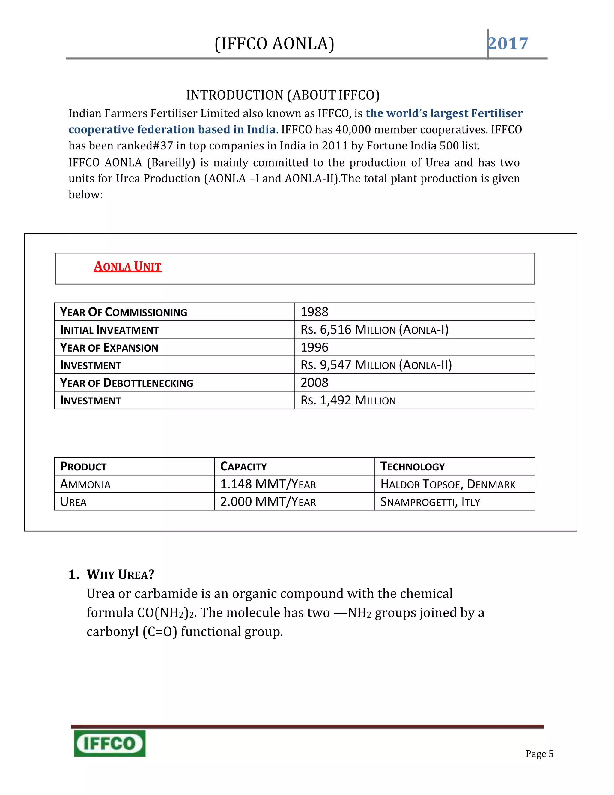
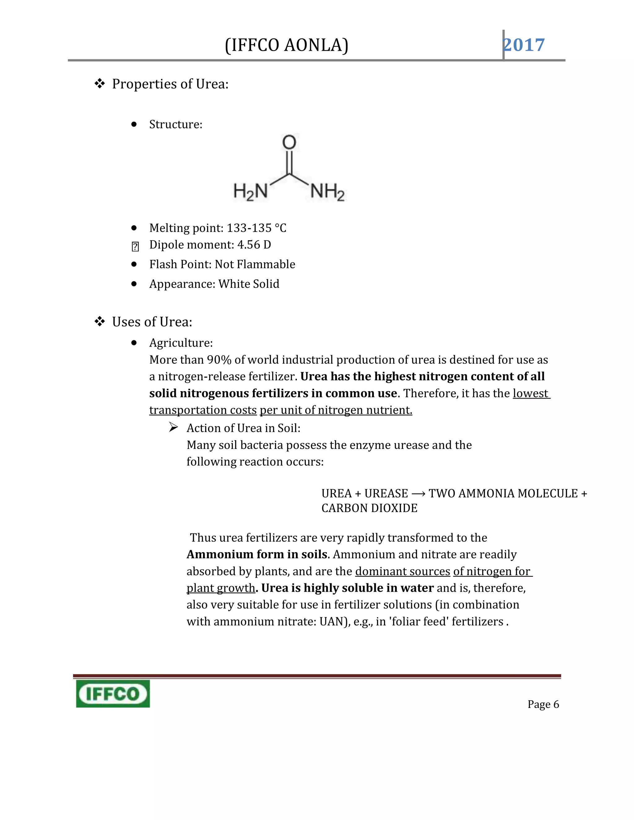
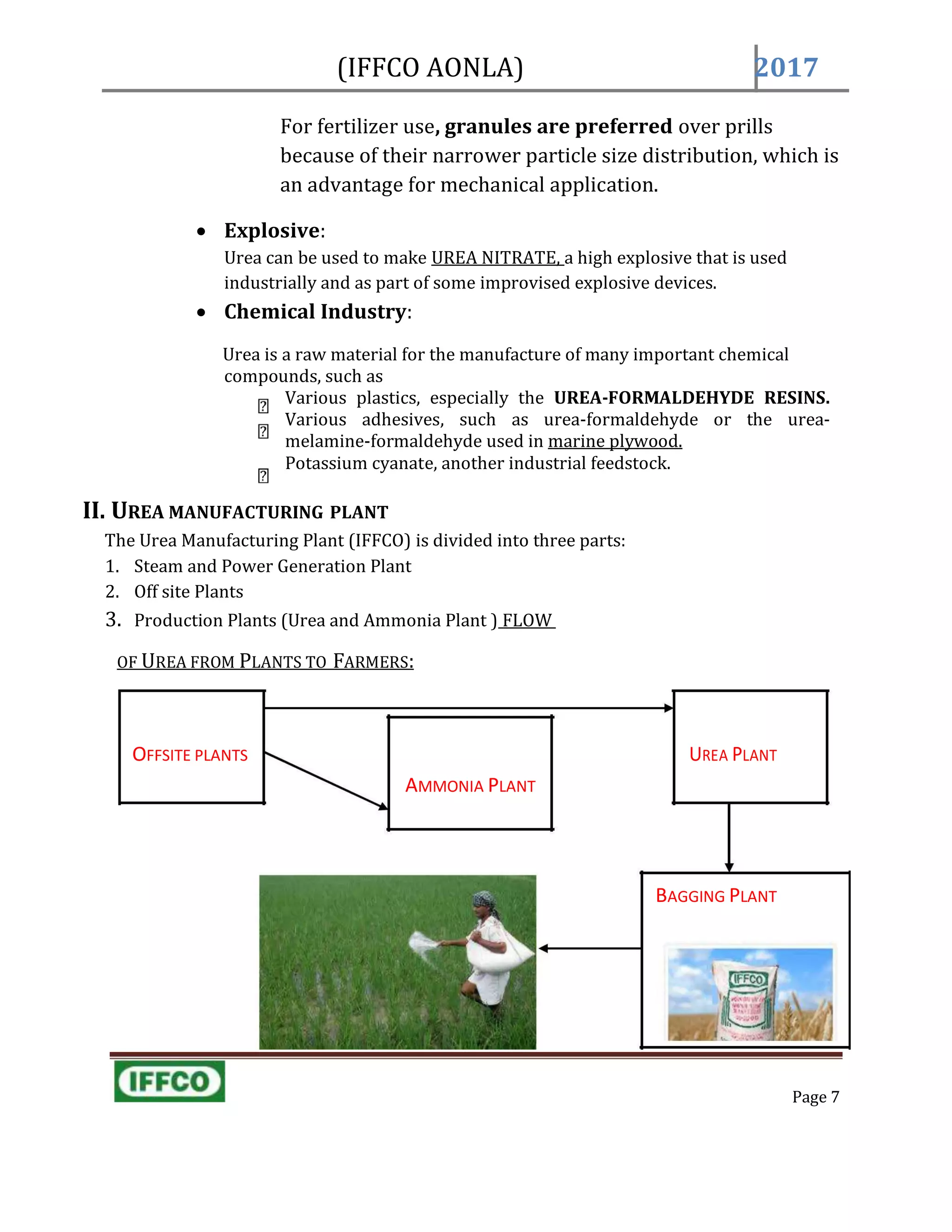
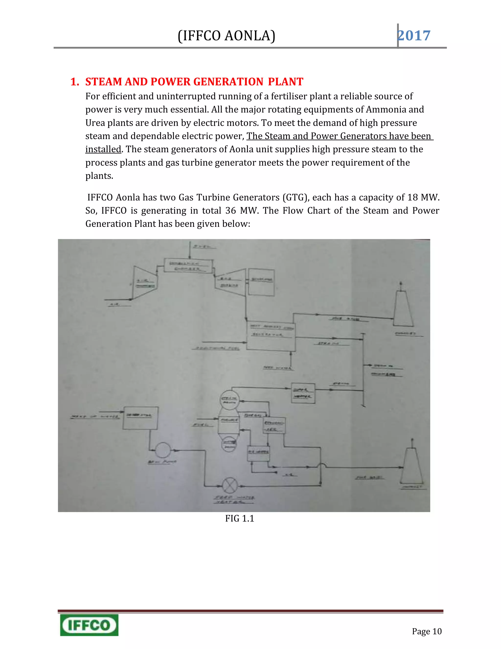
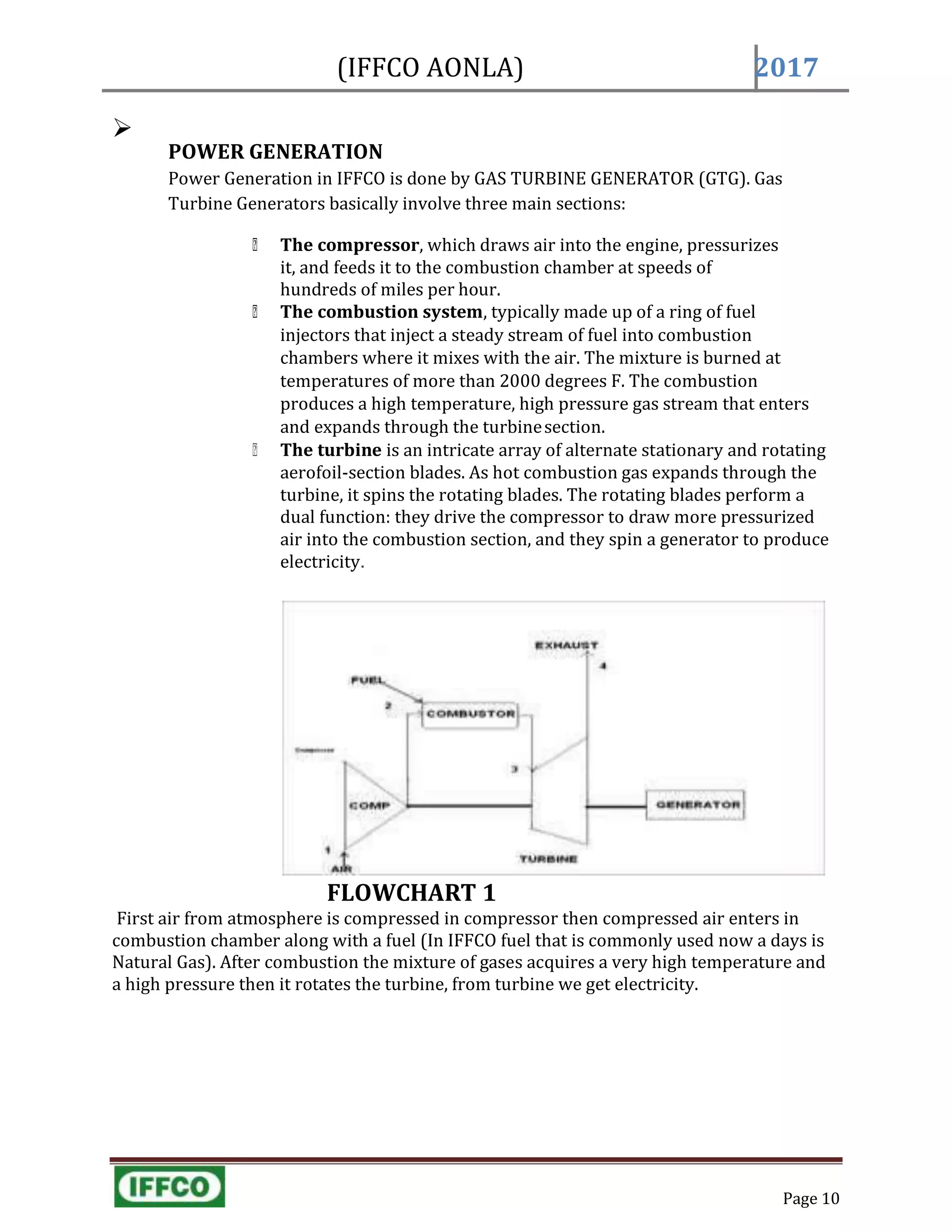
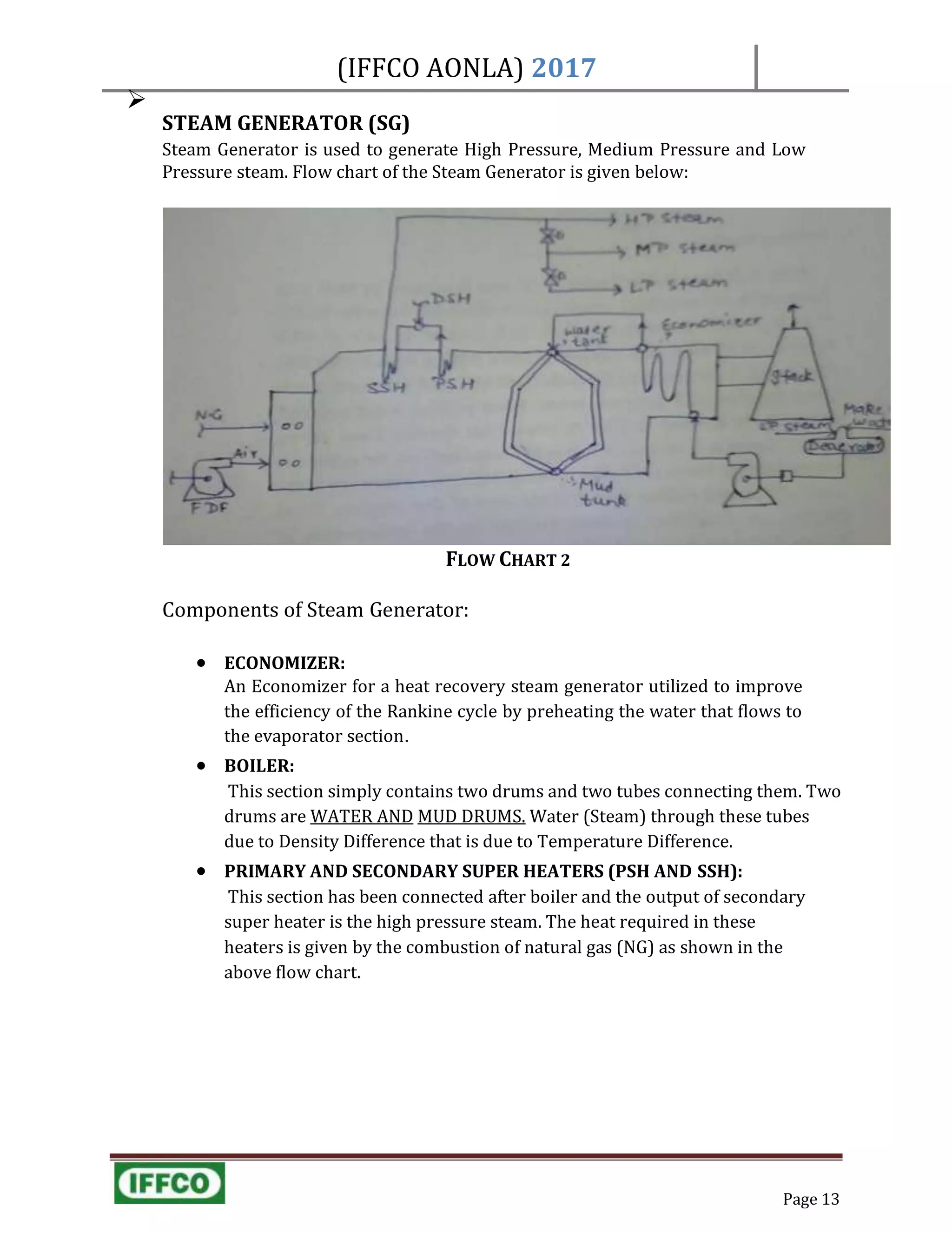
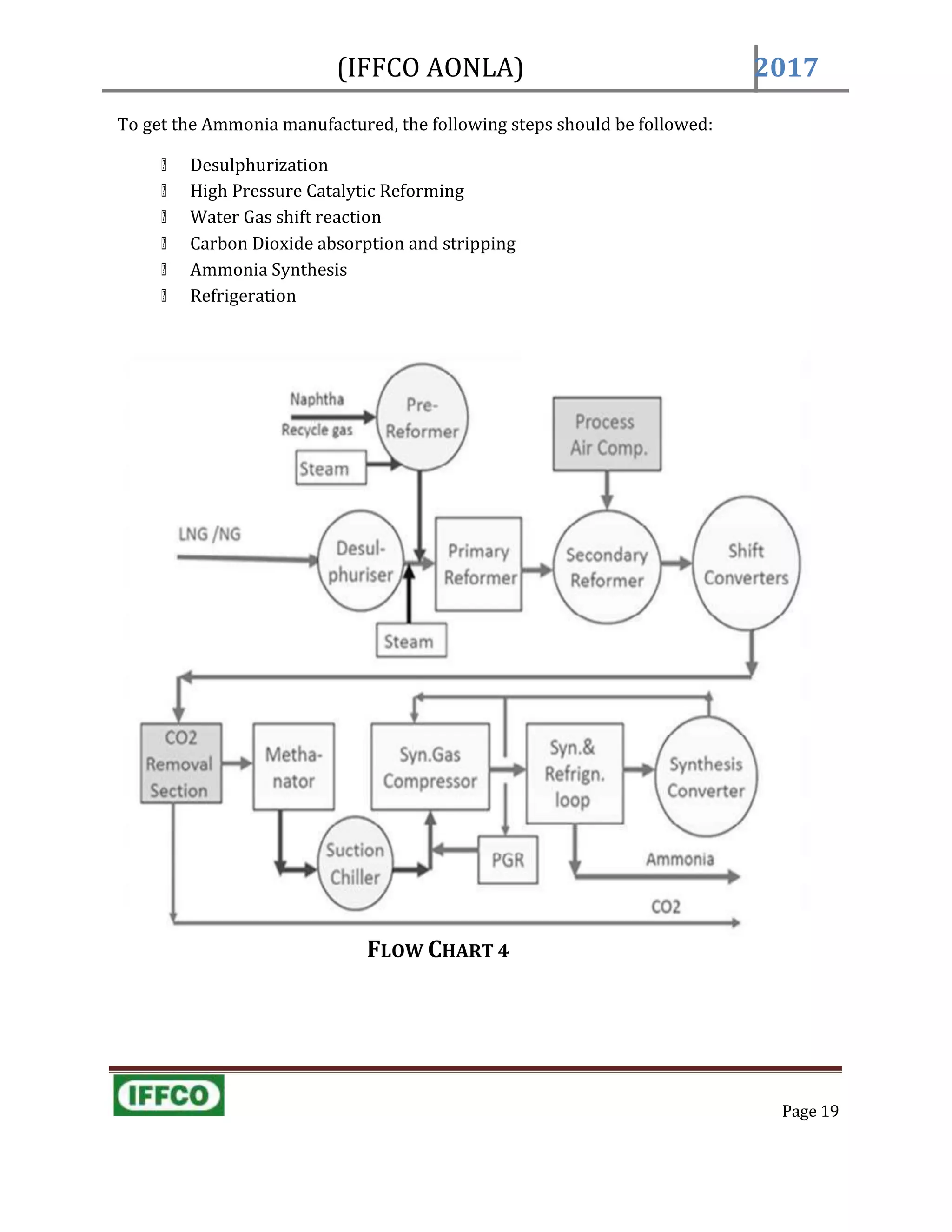
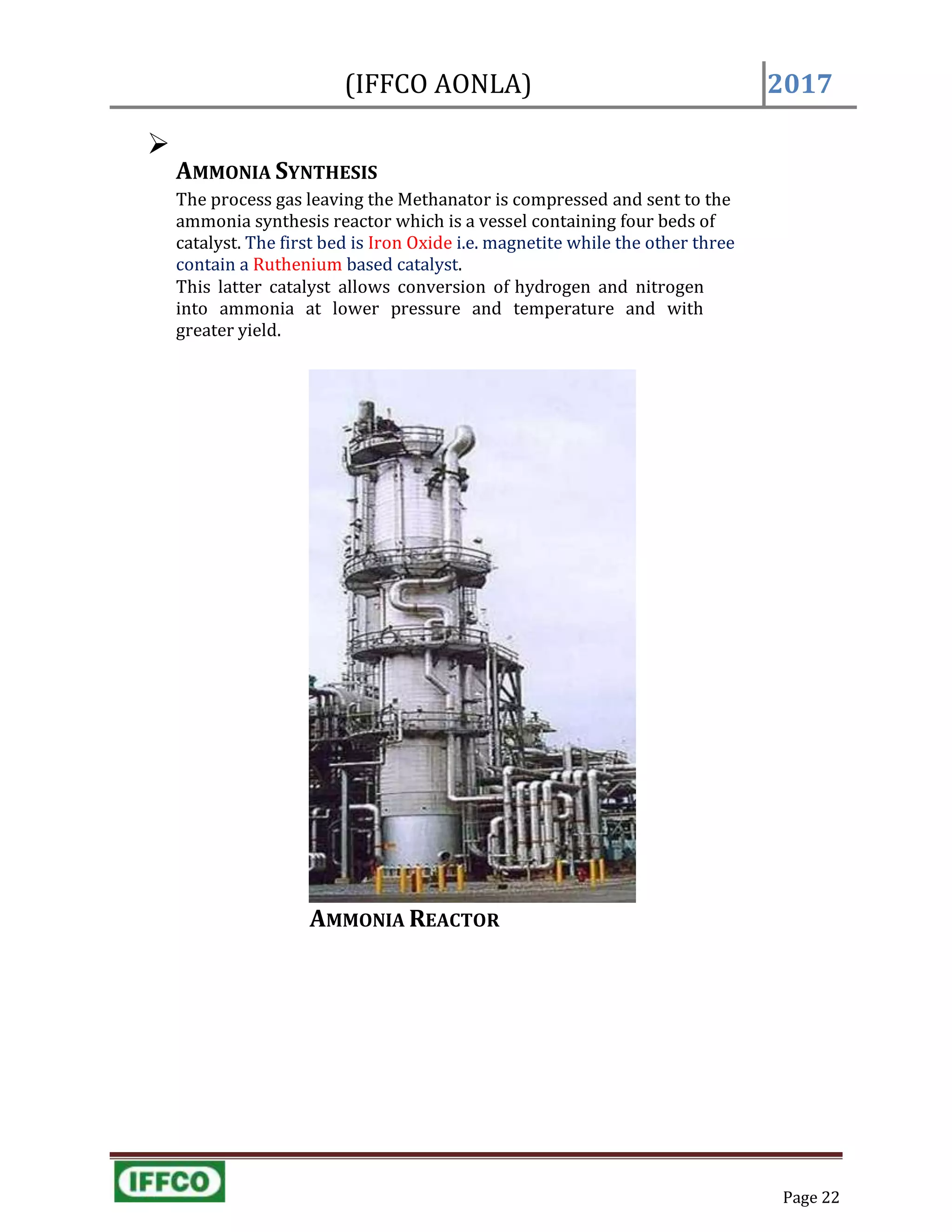
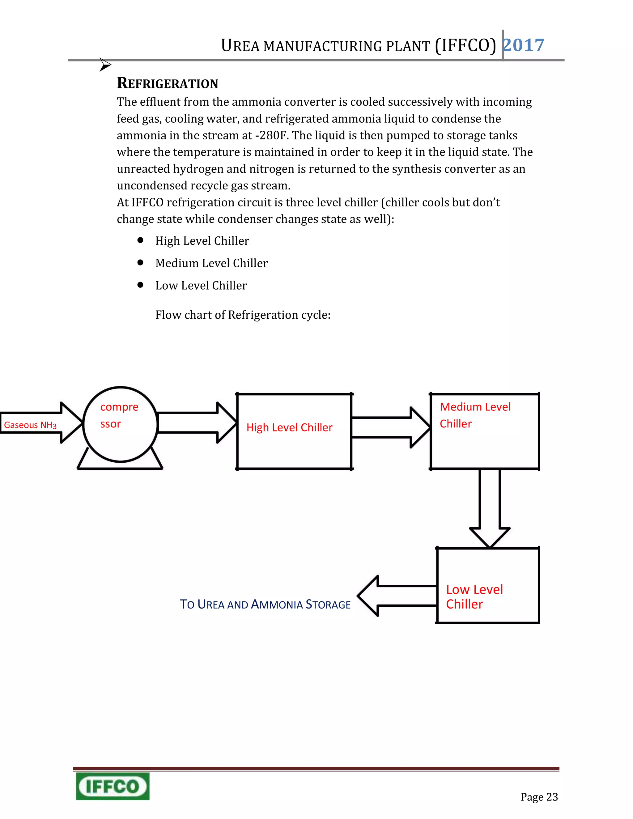
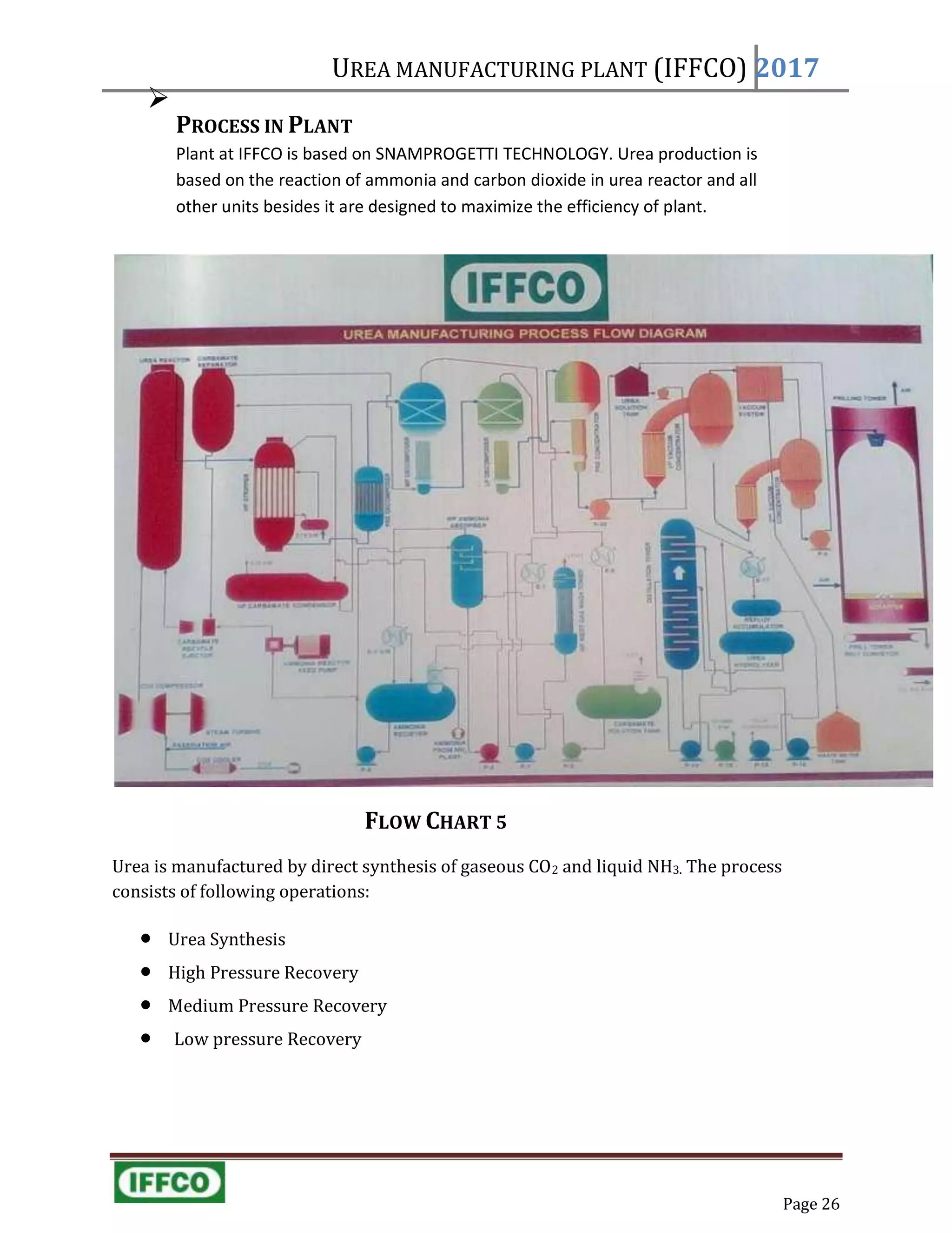
SlideShare a Scribd company logo
M.J.P. Rohilkhand University Bareilly
SUBMITTED TO:
Mr. ROHIT PAL
Dpt of Chemical Engineering
M.J.P. Rohilkhand university Bareilly
SUBMITTED BY:
ARIF KHAN (14CH14)
M.J.P. Rohilkhand university Bareilly
VT NO. 106
2017
TRAINING REPORT ON
VOCATIONAL TRAINING
DURATION: 6 JUNE 2017 TO 27 JULY 2017
UREA MANUFACTURING PLANT
(IFFCO AONLA) Bareilly
(IFFCO AONLA)
Page 2
2017
ABSTRACT
Indian Farmers Fertilizer Cooperative Limited (IFFCO) was established on 3rd November,
1967 as a multiunit cooperative organization of board objectives of augmenting fertilizer
production, ensuring fertilizer availability at farmers door step, strengthening cooperative
fertilizer distribution system and educating training and guiding the farmers for
improving agriculture productivity.
Aonla unit of IFFCO is one of the six natural gas based fertilizer plants to be setup in the
country on HBJ pipeline which runs through four states. The original HBJ pipeline
comes from Hazira. IFFCO Aonla is 18 km southwest of Bareilly-Aonla Road.
The project consists mainly of Ammonia plant, Urea plant and Offsite facilities like Water
Treatment System, Inert Gas Plant, Instrument Air Plant, Bagging Plant, Laboratory and
Storage for spares consumable and products. In addition of these infrastructure facilities
such as railways, siding etc. are also created. IFFCO Aonla was mechanically completed in
the record time of 36 months.
To get the maximum of the project IFFCO Aonla has two urea production units Urea-I and
Urea-II and each of these two units has two sub-units. Each of these two units has one prill
tower (common of two sub-units).
IFFCO Aonla also has facilities for the storage of Naptha that could be used as an
alternative fuel, when Natural Gas is not available. This contains liquid waste treatment
units in approximately each plant, that’s why IFFCO Aonla is zero liquid effluent discharge
plant.
(IFFCO AONLA)
Page 3
2017
ACKNOWLEDGEMENT
I would like to express my heartily gratitude to all those who gave me the valuable
opportunity to understand and comprehend and complete this project report. I would like
to thank Indian Farmers Fertilizer Cooperative Limited, Bareilly for providing me this
training and for guiding throughout the training.
I would like to specially thank MR. O.P. MATHUR (SM, Power plant, IFFCO) who
made this all possible for me.
Though it is tough to collect the necessary information within a short period of time, with
the support that I got from the Operators of different plants and most helpful library of
IFFCO, I was able to complete the report with complete analysis in due time.
(IFFCO AONLA) 2017
Table of Contents
I. INTRODUCTION...............................................................................................................................................................6

WHY UREA?............................................................................................................................6

Properties of Urea........................................................................................................7

Uses of Urea...............................................................................................................7
II. UREA MANUFACTURING PLANT..............................................................................................................................8

STEAM AND POWER GENERATION PLANT..........................................................................................................9

Power Generation.....................................10

Heat Recovery Steam Generators (HRSG)...11

Deaerator..................................................11

Steam Generator 12

NAPTHA STORAGE PLANT
13

Fire safety in naptha storage
13

OFFSITE PLANTS.............................................................................14

Raw Water Storage 14

Demineralized Water Plant
15

Cooling Towers 19

Effluent Treatment Plant
21

Instrument Air Plant
22
Inert Gas Plant 23
Ammonia Storage 24

AMMONIA PLANT ..........................................................................25
Desulphurization 27
Primary Reformer 28
Secondary Reformer
29
Shift Conversion 30

Condensate Stripping
31

Methanation 32

Ammonia Synthesis
33

Refrigeration 34

UREA PLANT ..................................................................................35

Reactions 36

Urea Synthesis 38

HP Stripper 39

HP Condensation 40

MP Section 40
(IFFCO AONLA) 2017
AONLA UNIT
YEAR OF COMMISSIONING 1988
INITIAL INVEATMENT RS. 6,516 MILLION (AONLA-I)
YEAR OF EXPANSION 1996
INVESTMENT RS. 9,547 MILLION (AONLA-II)
YEAR OF DEBOTTLENECKING 2008
INVESTMENT RS. 1,492MILLION
PRODUCT CAPACITY TECHNOLOGY
AMMONIA 1.148 MMT/YEAR HALDOR TOPSOE,DENMARK
UREA 2.000 MMT/YEAR SNAMPROGETTI, ITLY
AONLA UNIT
AONLA UNIT
INTRODUCTION (ABOUTIFFCO)
Indian Farmers Fertiliser Limited also known as IFFCO, is the world’s largest Fertiliser
cooperative federation based in India. IFFCO has 40,000 member cooperatives. IFFCO
has been ranked#37 in top companies in India in 2011 by Fortune India 500 list.
IFFCO AONLA (Bareilly) is mainly committed to the production of Urea and has two
units for Urea Production (AONLA –I and AONLA-II).The total plant production is given
below:
YEAR OF COMMISSIONING 1988
INITIAL INVEATMENT RS. 6,516 MILLION (AONLA-I)
YEAR OF EXPANSION 1996
INVESTMENT RS. 9,547 MILLION (AONLA-II)
YEAR OF DEBOTTLENECKING 2008
INVESTMENT RS. 1,492 MILLION
PRODUCT CAPACITY TECHNOLOGY
AMMONIA 1.148 MMT/YEAR HALDOR TOPSOE, DENMARK
UREA 2.000 MMT/YEAR SNAMPROGETTI, ITLY
1. WHY UREA?
Urea or carbamide is an organic compound with the chemical
formula CO(NH2)2. The molecule has two —NH2 groups joined by a
carbonyl (C=O) functional group.
Page 5
(IFFCO AONLA) 2017
 Properties of Urea:
 Structure:
 Melting point: 133-135 °C
Dipole moment: 4.56 D
 Flash Point: Not Flammable
 Appearance: White Solid
 Uses of Urea:
 Agriculture:
More than 90% of world industrial production of urea is destined for use as
a nitrogen-release fertilizer. Urea has the highest nitrogen content of all
solid nitrogenous fertilizers in common use. Therefore, it has the lowest
transportation costs per unit of nitrogen nutrient.
 Action of Urea in Soil:
Many soil bacteria possess the enzyme urease and the
following reaction occurs:
UREA + UREASE ⟶ TWO AMMONIA MOLECULE +
CARBON DIOXIDE
Thus urea fertilizers are very rapidly transformed to the
Ammonium form in soils. Ammonium and nitrate are readily
absorbed by plants, and are the dominant sources of nitrogen for
plant growth. Urea is highly soluble in water and is, therefore,
also very suitable for use in fertilizer solutions (in combination
with ammonium nitrate: UAN), e.g., in 'foliar feed' fertilizers .
Page 6
(IFFCO AONLA) 2017
AMMONIA PLANT
BAGGING PLANT
For fertilizer use, granules are preferred over prills
because of their narrower particle size distribution, which is
an advantage for mechanical application.
 Explosive:
Urea can be used to make UREA NITRATE, a high explosive that is used
industrially and as part of some improvised explosive devices.
 Chemical Industry:
Urea is a raw material for the manufacture of many important chemical
compounds, such as
Various plastics, especially the UREA-FORMALDEHYDE RESINS.
Various adhesives, such as urea-formaldehyde or the urea-
melamine-formaldehyde used in marine plywood.
Potassium cyanate, another industrial feedstock.
II. UREA MANUFACTURING PLANT
The Urea Manufacturing Plant (IFFCO) is divided into three parts:
1. Steam and Power Generation Plant
2. Off site Plants
3. Production Plants (Urea and Ammonia Plant ) FLOW
OF UREA FROM PLANTS TO FARMERS:
OFFSITE PLANTS UREA PLANT
Page 7
(IFFCO AONLA) 2017
Page 10
1. STEAM AND POWER GENERATION PLANT
For efficient and uninterrupted running of a fertiliser plant a reliable source of
power is very much essential. All the major rotating equipments of Ammonia and
Urea plants are driven by electric motors. To meet the demand of high pressure
steam and dependable electric power, The Steam and Power Generators have been
installed. The steam generators of Aonla unit supplies high pressure steam to the
process plants and gas turbine generator meets the power requirement of the
plants.
IFFCO Aonla has two Gas Turbine Generators (GTG), each has a capacity of 18 MW.
So, IFFCO is generating in total 36 MW. The Flow Chart of the Steam and Power
Generation Plant has been given below:
FIG 1.1
(IFFCO AONLA) 2017
Page 10

POWER GENERATION
Power Generation in IFFCO is done by GAS TURBINE GENERATOR (GTG). Gas
Turbine Generators basically involve three main sections:
The compressor, which draws air into the engine, pressurizes
it, and feeds it to the combustion chamber at speeds of
hundreds of miles per hour.
The combustion system, typically made up of a ring of fuel
injectors that inject a steady stream of fuel into combustion
chambers where it mixes with the air. The mixture is burned at
temperatures of more than 2000 degrees F. The combustion
produces a high temperature, high pressure gas stream that enters
and expands through the turbinesection.
The turbine is an intricate array of alternate stationary and rotating
aerofoil-section blades. As hot combustion gas expands through the
turbine, it spins the rotating blades. The rotating blades perform a
dual function: they drive the compressor to draw more pressurized
air into the combustion section, and they spin a generator to produce
electricity.
FLOWCHART 1
First air from atmosphere is compressed in compressor then compressed air enters in
combustion chamber along with a fuel (In IFFCO fuel that is commonly used now a days is
Natural Gas). After combustion the mixture of gases acquires a very high temperature and
a high pressure then it rotates the turbine, from turbine we get electricity.
(IFFCO AONLA) 2017
Page 10
So, now we have two options:

Exhaust gases of turbine at a temperature of about 500°C could be vented
into atmosphere.

We could also utilize the energy of these gases to generate steam.

HEAT RECOVERY STEAM GENERATORS (HRSG)
To the stream 4 in the above flow chart a HRSG unit is connected to utilize the heat
contained in the exhaust gases by converting water into HIGH PRESSURE STEAM. Exhaust
gases of HRSG is vented to atmosphere through stacks.
Gases enters in HRSG units are not sufficiently heated so as to obtain high pressure steam.
So, Heaters are provided in the HRSG units through which we obtain desired temperature
in the HRSG units.
The water that enters in the HRSG units to get converted into High Pressure Steam ,
first passed through Deaerator then, through BOILER FEEDWATER PUMP (BFW) water
is pumped to HRSG units and boiler.

DEAERATOR: Deaerator is a device that is used to remove mainly Oxygen and
Carbon Dioxide from feed water of plants.
Dissolved oxygen in boiler feed water causes corrosion damage in steam
systems by attaching to the walls of metal piping and other metallic equipment
and form oxides (rust). Dissolved Carbon Dioxide forms carbonic acid which
further leads to corrosion (rust).
The plant also contains a Steam Generator (SG) unit to generate HP steam.
Page 13
(IFFCO AONLA) 2017

STEAM GENERATOR (SG)
Steam Generator is used to generate High Pressure, Medium Pressure and Low
Pressure steam. Flow chart of the Steam Generator is given below:
FLOW CHART 2
Components of Steam Generator:
 ECONOMIZER:
An Economizer for a heat recovery steam generator utilized to improve
the efficiency of the Rankine cycle by preheating the water that flows to
the evaporator section.
 BOILER:
This section simply contains two drums and two tubes connecting them. Two
drums are WATER AND MUD DRUMS. Water (Steam) through these tubes
due to Density Difference that is due to Temperature Difference.
 PRIMARY AND SECONDARY SUPER HEATERS (PSH AND SSH):
This section has been connected after boiler and the output of secondary
super heater is the high pressure steam. The heat required in these
heaters is given by the combustion of natural gas (NG) as shown in the
above flow chart.
Page 13
(IFFCO AONLA) 2017
NAPTHA STORAGE PLANT

 WHAT IS NAPTHA?
Naphtha normally refers to a number of flammable liquid mixtures of hydrocarbons, i.e. a component
of natural gas condensate or a distillation product from petroleum, coal tar, or peat boiling in a
certain range and containing certain hydrocarbons. It is a broad term covering among the lightest
and most volatile fractions of the liquid hydrocarbons in petroleum. Naptha is a colorless to
reddish-brown volatile aromatic liquid, very similar to gasoline.
 NAPTHA IN PLANT
IFFCO buys Naptha from outer agencies and it comes in the plant through
trains. Pipelines are available with required pumps to store naptha in large
tanks. Naptha is used as a fuel in power and ammonia plant but now a days
it is not in use and in place of it Natural gas (from HAZIRA-BIJAPUR-
JAGDISHPUR (HBJ) Pipeline)is used. Still, for any emergency a sufficient
quantity of naptha has been kept in a tank.

FIRE SAFETY IN NAPTHA STORAGE
Because naptha is a mixture of flammable hydrocarbons so, a strong
safety is required.
Automatic Mechanism to extinguish fire:
Every tank is connected to two pipelines of FIRE SAFETY DEPARTMENT.
One pipe contains a heat sensitive liquid at 6 atm pressure and this
pipeline has been rounded through upper open face of tank and about 28
small bulbs (in a tank) have been connected to this pipeline and other
one has the provision for the flow of a mixture of foam and water to
extinguish fire.
So, in case of fire in tank temperature increases as a result of which the
bulbs get fused that leads to several holes in the pipeline, as a result of
which pressure in pipe decreases then
Page 13
(IFFCO AONLA) 2017
automatically entry valve of second pipe gets opened and mixture
of foam and water starts coming. So, this does not require labor
and is completely automatic system.
2. OFFSITE PLANTS
Following are the plants come under offsite section:
 Raw water system
 Water Treatment Plant (Demineralized Water Plant )
 Cooling Towers
 Effluent Treatment Plant
 Instrument Air Plant
 Inert Gas Generation Plant
 Ammonia Storage Plant
(IFFCO AONLA) 2017
Page 15
Flow chart of DM Plant is given below:
FLOW CHART 3
SILICA REMOVAL REACTION:
ReOH + H2SiO3 ⟶ ReHSiO3 + H2O
First water is passed through sand filter in which sand is thrown out from water
and then to cation and anion removal units which are completely filled with resin
and water is poured in the tanks from upper side and exit of water is at bottom of
tanks, so Resin adsorbs the cation and anion. The resin in the DM Plant keep
regenerating in short
(IFFCO AONLA) 2017
Page 15
intervals of time by passing it through different solutions (NaOH, HCl, H2SO4).
Degasifier removes acids like Carbonic acid and air is continuously passed
through degasifier.
FANS TO SUCK AIR FROM ATMOSPHERE USED IN DEGASIFIER UNIT
Reaction in Degasifier:
H2CO3 ⟶ H2O + CO2

COOLING TOWERS
Most of the units of any chemical plant are Heat Exchangers (may be condenser,
Boiler or Evaporator). So, every heat exchanger requires a cold fluid to absorb
heat and one hot fluid to releaseheat.
In most of the heat exchangers cold fluid is water and the plant to cool water
is called cooling tower.
Cooling Tower is also a type of heat exchanger and in IFFCO heat absorbing
fluid is air and heat releasing fluid is water. So, water cools down in this
process.
(IFFCO AONLA) 2017
Page 16
A VIEW OF COOLING TOWERS OF IFFCO
Round shapes in the above photo at the top are Induced Draft (ID) Fans. ID
Fans suck air from atmosphere passes it through water, so air comes in
contact with water and heat transfer takes place as a result of which water
cools down.
Chlorine (stored in yellow tanks) is also mixed in water to kill bacterias
and to increase its purity level. Hydro Chloric acid and Hydrogen Sulphate
are also mixed to maintain PH ofwater.
Page 17
UREA MANUFACTURING PLANT (IFFCO) 2017

EFFLUENT TREATMENT PLANT
Effluent treatment plant is for the treatment of waste water of Ammonia
and Urea Plant. Waste water contains a little bit ammonia, salts and
several other impurities. The flow chart of Effluent Treatment Plant is
given below:
Air out Steam out
CONTAMINATED
WASTE WATER
EFFLUENT TANK AIR STRIPPER STEAM
STRIPPER
Air in Steam in
GUARD POND
USED
FOR IRRIGATION
GUARD POND
(IFFCO AONLA) 2017
1. AMMONIA PLANT
Ammonia is a important raw material to manufacture Urea. Ammonia is
manufactured in Ammonia Plant. Ammonia plant is based on HALDOR TOPSOE
TECHNOLOGY.
To manufacture ammonia, we need hydrogen and nitrogen in gaseous form.
We get Nitrogen from Inert Gas (From Atmosphere) plant and hydrogen from
Natural Gas.
Natural Gas is supplied at the battery limit by GAS AUTHORITY OF INDIA LIMITED
(GAIL) from gas wells located in Bombay through HAZIRA-BIJAPUR-JAGDISHPUR
(HBJ) Pipeline.
GAIL has plans to set up certain facilities for extraction of higher hydrocarbons
from the gas due to which the gas would become leaner.
Properties of Rich and Lean Gas (Gas by GAIL)
Page 18
(IFFCO AONLA) 2017
To get the Ammonia manufactured, the following steps should be followed:
Desulphurization
High Pressure Catalytic Reforming
Water Gas shift reaction
Carbon Dioxide absorption and stripping
Ammonia Synthesis
Refrigeration
FLOW CHART 4
Page 19
(IFFCO AONLA) 2017

DESULPHURIZATION
Natural Gas contains sulphur compounds in the form of sulphides, disulphides,
mercaptions, thiophenes etc. which are poisonous to the catalysts used in
Ammonia plant. Two steps in Desulphurization:
Hydrogenation of sulphur compounds in the presence of catalyst.
Hydrogen reacts with organic sulphur compounds to form hydrogen
sulphide in HYDROGENATOR.
This hydrogen sulphide is absorbed by zincoxide in sulphur
absorber.

HYDROGENATION
Common type of sulphur compounds present in Natural Gas:
Hydrogen Sulphide (H2S)
Mercaption sulphur (R-SH)
Sulphides (CH3-S-CH3)
Disulphides (CH3-S-S-CH3)
Cyclic Sulphides (-S-CH2-)
Page 20
Reactions:
ZnO + H2S ⥨ ZnS + H2O
ZnO + COS ⥨ ZnS + CO2
Now the gas is sent to primary reformer.

PRIMARY REFORMER
In primary reformer, hydrocarbons are converted into hydrogen.
. Reforming Reactions:
CnH2n+2 + nH2O + Heat ⟶ nCO + (2n+1)H2
Heat is supplied by burning mixed fuel gas in 576 fired wall burners and 208 tubes.
Catalyst used in primary reformer is nickel based.
SECONDARY REFORMER
In the secondary reformer combustion and reaction of the reformed primary gas with
process air takes place. Secondary reformer is a conical cylindrical vessel. High pressure
shell is insulated from inside with refractory material to protect shell from high
temperature. The reaction with air in the secondary reformer combustionzone is as
follows:
3H2 + 1.5O2 + 3.715N2 ⥨ 2H2O + 3.175N2 + H2O 2CH4 + 1.5O2 + 13.00N2 ⥨ CO2 + CO + 4H2 +
13.00N2 + Heat
Page 21
(IFFCO AONLA) 2017
Page 22
(IFFCO AONLA) 2017

AMMONIA SYNTHESIS
The process gas leaving the Methanator is compressed and sent to the
ammonia synthesis reactor which is a vessel containing four beds of
catalyst. The first bed is Iron Oxide i.e. magnetite while the other three
contain a Ruthenium based catalyst.
This latter catalyst allows conversion of hydrogen and nitrogen
into ammonia at lower pressure and temperature and with
greater yield.
AMMONIA REACTOR
Page 23
UREA MANUFACTURING PLANT (IFFCO) 2017
Gaseous NH3
Low Level

REFRIGERATION
The effluent from the ammonia converter is cooled successively with incoming
feed gas, cooling water, and refrigerated ammonia liquid to condense the
ammonia in the stream at -280F. The liquid is then pumped to storage tanks
where the temperature is maintained in order to keep it in the liquid state. The
unreacted hydrogen and nitrogen is returned to the synthesis converter as an
uncondensed recycle gas stream.
At IFFCO refrigeration circuit is three level chiller (chiller cools but don’t
change state while condenser changes state as well):
 High Level Chiller
 Medium Level Chiller
 Low Level Chiller
Flow chart of Refrigeration cycle:
compre Medium Level
ssor High Level Chiller Chiller
TO UREA AND AMMONIA STORAGE Chiller
UREA MANUFACTURING PLANT (IFFCO) 2017

REACTIONS IN UREA PLANT :
Urea is produced from ammonia and carbon dioxide in two equilibrium
reactions:
2NH3 (Liq.) + CO2 (g) ⥨ NH2COONH4 Exothermic Reaction(Ammonium carbamate)
NH2COONH4 ⥨ NH2CONH2 + Endothermic Reaction (Urea)
Overall reaction is Exothermic.
Reaction 1 is favored when solution pressure is greater than
decomposition pressure.
Decomposition pressure is the pressure at which carbamate decomposes into
ammonia and carbon dioxide.
NH2COONH4 ⥨ 2NH3 + CO2
Decomposition pressure is a function of concentration of Ammonia and
temperature.
The urea manufacturing process, is designed to maximize these reactions
while inhibiting biuret formation: 2NH2CONH2 ⥨ NH2CONHCONH2 + NH3
(Biuret)
This reaction is undesirable, not only because it lowers the yield of urea, but
because biuret burns the leaves of plants. This means that urea which contains high
levels of biuret isnot suitable for use as a fertiliser.
Page 24
Page 26
UREA MANUFACTURING PLANT (IFFCO) 2017

PROCESS IN PLANT
Plant at IFFCO is based on SNAMPROGETTI TECHNOLOGY. Urea production is
based on the reaction of ammonia and carbon dioxide in urea reactor and all
other units besides it are designed to maximize the efficiency of plant.
FLOW CHART 5
Urea is manufactured by direct synthesis of gaseous CO2 and liquid NH3. The process
consists of following operations:
 Urea Synthesis
 High Pressure Recovery
 Medium Pressure Recovery
 Low pressure Recovery
Page 26
(IFFCO AONLA) 2017
 Urea Concentration
 Waste Water Treatment
 Urea Prilling
 UREA SYNTHESIS
Both the raw materials are supplied by ammonia plant. Liquid Ammonia along
with carbonate solution pumped in the reactor at bottom. CO2 along with
atmospheric air in also pumped in reactor.
UREA REACTOR
Following reaction occurs in this reactor:
2NH3 (l) + CO2 (g) ⥨ NH2COONH4 Exothermic Reaction(Ammonium
Carbamate)
NH2COONH4 ⥨ NH2CONH2 + Endothermic Reaction (Urea)
Overall reaction is Exothermic.
Oxygen in the air (supplied with carbon dioxide) forms a passive oxide layer on
the insides of vessel surfaces to prevent corrosion by carbamate and urea.
The Reactor product contains 38 % by weight Urea.
 HIGH PRESSURE STRIPPER
Urea enters the tube of HP Stripper operating at 147 atm/190 °C which is falling
type heat exchanger. The stripper tubes are provided with liquid dividers also
called ferrules.
Urea reactor supplies a mixture of urea, ammonia, carbon dioxide, water and
carbamate. In the HP Stripper unconverted is converted into ammonia and
carbon dioxide by using Henry’s Law.
HENRY’S LAW in HP stripper:
Excess of ammonia is passed due to which partial vapor pressure of ammonia
increases, by Henry’s law concentration of ammonia should increase in solution
that could only be achieved by decomposition of ammonium carbamate.
Following reaction occurs in HP stripper: NH2COONH4
⥨ 2NH3 (Liq.) + CO2 (g)
Page 27
Page 28
 HIGH PRESSURE CONDENSATION AND SEPARATION
Gases from high pressure stripper enter in HP Carbamate condenser in
which most of the ammonia and carbon dioxide reacts to form ammonium
carbamate.
Condensate from HP Carbamate condenser is passed to HP Carbamate
Separator which passes liquid carbamate again to Urea Reactor and urea to
MP Decomposer.
 MEDIUM PRESSURE SECTION
The MP Decomposer consists of three parts. The top part is MP Separator, the
middle is MP Decomposer and bottom one is MP Urea solution holder. The urea
from stripper is let down to 18 atm from 147 atm. As a result of pressure let down
some solution flashes, producing vapors of ammonia carbon dioxide and water. The
heat of vaporization is taken from 207 to 140
°C. This solution is then distributed over bed of pall rings in the MP Separator. The
vapors rising from the MP Decomposer below come into intimate contact. Thus
more carbamate is decomposed by hot vapors. These vapors now filled out of MP
Condenser.
The MP Absorber consists of two sections. The top section sis called the
rectification section and the bottom portion is called absorber section. The liquid
and vapor mixture from medium pressure condenser enters the absorber portion
of MP absorber comes out through a sparer. A liquid level is always maintained
above the sparer to absorb vapors of ammonia carbon dioxide and water.
The purpose of this section is to partially strip out the reactants, ammonia and
carbon dioxide from the urea solution and, after their condensation in water, to
recycle the obtained
Page 28
solution to the reactor, together with the ammonia and carbon dioxide aqueous
solution resulting from the downstream sections of the plant. The ammonia excess
is separated in this section and recycled to the reactor separately. A distillation
column is provided for this purpose. The operating pressure is 17 bar g. A
particular feature is included in this section.
Ammonia and carbon dioxide are partially condensed in the shell of a preheater
within the vacuum section, thus recovering some energy in the form of 200kg of
steam per ton of urea. Another particular characteristic of the MP section is the
washing of the so-called inerts (CO, H2 and CH4 contained mainly in the carbon
dioxide and the passivation air). As already emphasized, the quantity of
passivation air in the Snamprogetti technology is very small (one third compared
with other technologies). It is therefore easy to recover ammonia from the inerts
without the risk of explosion mainly due to H2/O2 mixtures. No hydrogen removal
from carbon dioxide is required.
 LOW PRESSURE SECTION
Further stripping of ammonia and carbon dioxide is made in the LP section,
operating at 3.5 bar g. The vapors, containing ammonia and carbon dioxide, are
condensed and recycled to the reactor via the MP section. An appropriately sized
tank is provided in this section to collect all the solutions from the plant when it is
shut down for long time. Therefore, in no circumstances are solutions discharged
from the plant.
 VACUUM CONCENTRATION
The urea solution leaving the LP section is about 70% b.w. and contains small
quantities of ammonia and carbon dioxide. The final concentration of the urea
solution (99.8% b.w.) is made under vacuum in two steps at 0.3 and 0.03 bar abs.
for
VAPORS HYDROLYZER
AMMONIA TO REACTOR
OVERHEAD
CONDENSER
the prilled product, and in one or two steps for the granular product, according to
the granulation technology chosen.
An important feature of this section is the pre concentration of the urea solution to
about 86% b.w. The necessary heat is provided by partial condensation of the
vapors (ammonia and carbon dioxide essentially) from the MP section evaporator.
Particular care is taken in the design of this section to minimize temperatures and
residence times so as to keep the biuret at minimum values. A simple solution has
been found to the problem of lump formation in the second vacuum separator: lump
formation is prevented by wetting the internal walls of the separator by means of a
small recycle of molten urea.
 PROCESS CONDENSATE TREATMENT
The excellent result achieved by Snamprogetti Technology in the treatment of
waste water from urea plants has received worldwide recognition.
All possible and convenient heat recoveries have been introduced into
this section in order to minimize energy consumption.
FLOW CHART OF WASTE WATER TREATMENT IN UREA PLANT:
UREA ⟶ NH3 +
BUFFER WASTE
CO2
VAPORS
WASTE WATER
WATER TANK
DISTILLATION
TANK TOWER
Page 30
 UREA PRILLING
Prilling is the easiest technology to manufacture solid urea with commercially valid
chemical and physical characteristics. Molten urea (99.8% b.w.) is sprayed at the top of
the prill tower, at a effective height of 72.5m and height from ground 94m which is
according to climatic conditions; at the bottom, essentially spherical urea particles,
namely prills, are collected and sufficiently cooled in order to be sent to storage or
directly to the bagging section without screening, coating or any other treatment. At the
top of prill tower a bucket with holes at its side surface is
PRILLING TOWER
rotated with the help of motor. Due to centrifugal force, urea in liquid form
comes out of bucket through holes of surfaces. Natural Draft fan converts urea
in the solid form, during the air time (time of urea droplets in air) of urea
granules.
Page31
III. References
 Ammonia-I Training Manual, IFFCO Aonla.
 Offsite Plants Training Manual, IFFCO Aonla.
 Power Plant Training Manual, IFFCO Aonla.
 Urea-I Training Manual, IFFCO Aonla. Urea -
Wikipedia, the free encyclopedia,
http://en.wikipedia.org/wiki/Urea
Page 32

More Related Content

What's hot

Training Report of IFFCO KALOL_Daxit Akbari
Training Report of IFFCO KALOL_Daxit AkbariTraining Report of IFFCO KALOL_Daxit Akbari
Training Report of IFFCO KALOL_Daxit Akbari
DAXIT AKBARI 🇮🇳
 
Iffco summer trainning presentation
Iffco summer trainning presentationIffco summer trainning presentation
Iffco summer trainning presentation
hmthimanshu
 
iffco_report
iffco_reportiffco_report
iffco_report
Kartik Sati
 
IFFCO Industrial Training ppt
IFFCO Industrial Training pptIFFCO Industrial Training ppt
IFFCO Industrial Training ppt
Mithilesh Rajbhar
 
Report on "IFFCO-KANDLA UNIT by Darshan-JEC KUKAS,JAIPUR
Report on "IFFCO-KANDLA UNIT by Darshan-JEC KUKAS,JAIPURReport on "IFFCO-KANDLA UNIT by Darshan-JEC KUKAS,JAIPUR
Report on "IFFCO-KANDLA UNIT by Darshan-JEC KUKAS,JAIPUR
Darshan Singh
 
aniruddh training report
aniruddh training reportaniruddh training report
aniruddh training report
Aniruddh Singh Shekhawat
 
IFFCO INTERNSHIP REPORT.docx
IFFCO INTERNSHIP REPORT.docxIFFCO INTERNSHIP REPORT.docx
IFFCO INTERNSHIP REPORT.docx
SAGAR SUTAR
 
Summer Internship Report Gourav Kumar Pandit 121234
Summer Internship Report Gourav Kumar Pandit 121234Summer Internship Report Gourav Kumar Pandit 121234
Summer Internship Report Gourav Kumar Pandit 121234
Kumar Gourav
 
Indian Oil: Vocational Training Report 2013
Indian Oil: Vocational Training Report 2013Indian Oil: Vocational Training Report 2013
Indian Oil: Vocational Training Report 2013
Pawan Kumar
 
Corporate presentation on ONGC
Corporate presentation on ONGCCorporate presentation on ONGC
Corporate presentation on ONGC
Sanket Singh
 
Internship Report FFC
Internship Report FFCInternship Report FFC
Internship Report FFC
Zeshan Aziz
 
HPCL Report Final
HPCL Report FinalHPCL Report Final
HPCL Report Final
Ramya Emandi
 
Iocl training report
Iocl training reportIocl training report
Iocl training report
Amitgomey
 
FINAL TRAINING REPORT ROHIT GOYAL NIT Calicut
FINAL TRAINING REPORT ROHIT GOYAL NIT CalicutFINAL TRAINING REPORT ROHIT GOYAL NIT Calicut
FINAL TRAINING REPORT ROHIT GOYAL NIT Calicut
ROHIT GOYAL
 
Nfl project report
Nfl project reportNfl project report
Nfl project report
Justin Fieber
 
TRAINING REPORT-A
TRAINING REPORT-ATRAINING REPORT-A
TRAINING REPORT-A
Ayushi Pandey
 
Hpcl Operations Mgmt
Hpcl Operations MgmtHpcl Operations Mgmt
Hpcl Operations Mgmt
DEEPAK DODDAMANI
 
Presentation on iffco
Presentation on iffcoPresentation on iffco
Presentation on iffco
satya pal
 
IOCL Vadodara Summer Internship Report
IOCL Vadodara Summer Internship ReportIOCL Vadodara Summer Internship Report
IOCL Vadodara Summer Internship Report
KrishnaKantNayak2
 
Project report on pa 2
Project report on pa 2Project report on pa 2
Project report on pa 2
sandeep choudhary
 

What's hot (20)

Training Report of IFFCO KALOL_Daxit Akbari
Training Report of IFFCO KALOL_Daxit AkbariTraining Report of IFFCO KALOL_Daxit Akbari
Training Report of IFFCO KALOL_Daxit Akbari
 
Iffco summer trainning presentation
Iffco summer trainning presentationIffco summer trainning presentation
Iffco summer trainning presentation
 
iffco_report
iffco_reportiffco_report
iffco_report
 
IFFCO Industrial Training ppt
IFFCO Industrial Training pptIFFCO Industrial Training ppt
IFFCO Industrial Training ppt
 
Report on "IFFCO-KANDLA UNIT by Darshan-JEC KUKAS,JAIPUR
Report on "IFFCO-KANDLA UNIT by Darshan-JEC KUKAS,JAIPURReport on "IFFCO-KANDLA UNIT by Darshan-JEC KUKAS,JAIPUR
Report on "IFFCO-KANDLA UNIT by Darshan-JEC KUKAS,JAIPUR
 
aniruddh training report
aniruddh training reportaniruddh training report
aniruddh training report
 
IFFCO INTERNSHIP REPORT.docx
IFFCO INTERNSHIP REPORT.docxIFFCO INTERNSHIP REPORT.docx
IFFCO INTERNSHIP REPORT.docx
 
Summer Internship Report Gourav Kumar Pandit 121234
Summer Internship Report Gourav Kumar Pandit 121234Summer Internship Report Gourav Kumar Pandit 121234
Summer Internship Report Gourav Kumar Pandit 121234
 
Indian Oil: Vocational Training Report 2013
Indian Oil: Vocational Training Report 2013Indian Oil: Vocational Training Report 2013
Indian Oil: Vocational Training Report 2013
 
Corporate presentation on ONGC
Corporate presentation on ONGCCorporate presentation on ONGC
Corporate presentation on ONGC
 
Internship Report FFC
Internship Report FFCInternship Report FFC
Internship Report FFC
 
HPCL Report Final
HPCL Report FinalHPCL Report Final
HPCL Report Final
 
Iocl training report
Iocl training reportIocl training report
Iocl training report
 
FINAL TRAINING REPORT ROHIT GOYAL NIT Calicut
FINAL TRAINING REPORT ROHIT GOYAL NIT CalicutFINAL TRAINING REPORT ROHIT GOYAL NIT Calicut
FINAL TRAINING REPORT ROHIT GOYAL NIT Calicut
 
Nfl project report
Nfl project reportNfl project report
Nfl project report
 
TRAINING REPORT-A
TRAINING REPORT-ATRAINING REPORT-A
TRAINING REPORT-A
 
Hpcl Operations Mgmt
Hpcl Operations MgmtHpcl Operations Mgmt
Hpcl Operations Mgmt
 
Presentation on iffco
Presentation on iffcoPresentation on iffco
Presentation on iffco
 
IOCL Vadodara Summer Internship Report
IOCL Vadodara Summer Internship ReportIOCL Vadodara Summer Internship Report
IOCL Vadodara Summer Internship Report
 
Project report on pa 2
Project report on pa 2Project report on pa 2
Project report on pa 2
 

Similar to IFFCO Training Report 2017- Arif Khan

Training report of aniruddha vashishtha
Training report of aniruddha vashishthaTraining report of aniruddha vashishtha
Training report of aniruddha vashishtha
Aniruddha Vashishtha
 
Nfl project report
Nfl project reportNfl project report
Nfl project report
Justin Fieber
 
Project of iffco
Project of iffcoProject of iffco
Project of iffco
axay0853
 
Labor Welfare of KRIBHCO Employees
Labor Welfare of KRIBHCO Employees Labor Welfare of KRIBHCO Employees
Labor Welfare of KRIBHCO Employees
Vipul Sachan
 
IFFCO Industrial Training Evaluation.pptx
IFFCO Industrial Training Evaluation.pptxIFFCO Industrial Training Evaluation.pptx
IFFCO Industrial Training Evaluation.pptx
Abhay Rajput
 
Development of integrated loose fruit collector machine for oil palm plantations
Development of integrated loose fruit collector machine for oil palm plantationsDevelopment of integrated loose fruit collector machine for oil palm plantations
Development of integrated loose fruit collector machine for oil palm plantations
journalBEEI
 
Fin. working capital aakriti
Fin. working capital   aakritiFin. working capital   aakriti
Fin. working capital aakriti
Aakriti Rohatgi
 
A Report on 2 week "In-Plant Training" done in FACT Ltd,Udyogmandal
A Report on 2 week "In-Plant Training" done in FACT Ltd,Udyogmandal A Report on 2 week "In-Plant Training" done in FACT Ltd,Udyogmandal
A Report on 2 week "In-Plant Training" done in FACT Ltd,Udyogmandal
Rajesh Gangireddy
 
FACT Internship Report (Mechanical Branch)
FACT Internship Report (Mechanical Branch)FACT Internship Report (Mechanical Branch)
FACT Internship Report (Mechanical Branch)
Bennet Hailink
 
Recruitment and selection part (2)
Recruitment and selection part (2)Recruitment and selection part (2)
Recruitment and selection part (2)
Akhil Mankotia
 
report for company indu swift
report for company indu swift report for company indu swift
report for company indu swift
Ifzal Hussain
 
Industrial Biotechnology China News 201101.pdf
Industrial Biotechnology China News 201101.pdfIndustrial Biotechnology China News 201101.pdf
Industrial Biotechnology China News 201101.pdf
CCM Intelligence
 
Exploring market potential of ammonia absorption refrigeration plant in ferti...
Exploring market potential of ammonia absorption refrigeration plant in ferti...Exploring market potential of ammonia absorption refrigeration plant in ferti...
Exploring market potential of ammonia absorption refrigeration plant in ferti...
Supa Buoy
 
Fertilizer
FertilizerFertilizer
Fertilizer
Santosh Mariyappan
 
Biodiesel production from_moringa_seeds
Biodiesel production from_moringa_seedsBiodiesel production from_moringa_seeds
Biodiesel production from_moringa_seeds
Drumstick Moringa
 
Sweet and sour experience of commissioning 1
Sweet and sour experience of commissioning 1Sweet and sour experience of commissioning 1
Sweet and sour experience of commissioning 1
Prem Baboo
 
Rice husk ash fuel to wealth - for finance, subsidy & project related suppo...
Rice husk ash   fuel to wealth - for finance, subsidy & project related suppo...Rice husk ash   fuel to wealth - for finance, subsidy & project related suppo...
Rice husk ash fuel to wealth - for finance, subsidy & project related suppo...
Radha Krishna Sahoo
 
Ci4301487491
Ci4301487491Ci4301487491
Ci4301487491
IJERA Editor
 
Palmoil2
Palmoil2Palmoil2
Palmoil2
ekagiri
 
Vinati Organics Report- April 16
Vinati Organics Report- April 16Vinati Organics Report- April 16
Vinati Organics Report- April 16
Gaurav Singh
 

Similar to IFFCO Training Report 2017- Arif Khan (20)

Training report of aniruddha vashishtha
Training report of aniruddha vashishthaTraining report of aniruddha vashishtha
Training report of aniruddha vashishtha
 
Nfl project report
Nfl project reportNfl project report
Nfl project report
 
Project of iffco
Project of iffcoProject of iffco
Project of iffco
 
Labor Welfare of KRIBHCO Employees
Labor Welfare of KRIBHCO Employees Labor Welfare of KRIBHCO Employees
Labor Welfare of KRIBHCO Employees
 
IFFCO Industrial Training Evaluation.pptx
IFFCO Industrial Training Evaluation.pptxIFFCO Industrial Training Evaluation.pptx
IFFCO Industrial Training Evaluation.pptx
 
Development of integrated loose fruit collector machine for oil palm plantations
Development of integrated loose fruit collector machine for oil palm plantationsDevelopment of integrated loose fruit collector machine for oil palm plantations
Development of integrated loose fruit collector machine for oil palm plantations
 
Fin. working capital aakriti
Fin. working capital   aakritiFin. working capital   aakriti
Fin. working capital aakriti
 
A Report on 2 week "In-Plant Training" done in FACT Ltd,Udyogmandal
A Report on 2 week "In-Plant Training" done in FACT Ltd,Udyogmandal A Report on 2 week "In-Plant Training" done in FACT Ltd,Udyogmandal
A Report on 2 week "In-Plant Training" done in FACT Ltd,Udyogmandal
 
FACT Internship Report (Mechanical Branch)
FACT Internship Report (Mechanical Branch)FACT Internship Report (Mechanical Branch)
FACT Internship Report (Mechanical Branch)
 
Recruitment and selection part (2)
Recruitment and selection part (2)Recruitment and selection part (2)
Recruitment and selection part (2)
 
report for company indu swift
report for company indu swift report for company indu swift
report for company indu swift
 
Industrial Biotechnology China News 201101.pdf
Industrial Biotechnology China News 201101.pdfIndustrial Biotechnology China News 201101.pdf
Industrial Biotechnology China News 201101.pdf
 
Exploring market potential of ammonia absorption refrigeration plant in ferti...
Exploring market potential of ammonia absorption refrigeration plant in ferti...Exploring market potential of ammonia absorption refrigeration plant in ferti...
Exploring market potential of ammonia absorption refrigeration plant in ferti...
 
Fertilizer
FertilizerFertilizer
Fertilizer
 
Biodiesel production from_moringa_seeds
Biodiesel production from_moringa_seedsBiodiesel production from_moringa_seeds
Biodiesel production from_moringa_seeds
 
Sweet and sour experience of commissioning 1
Sweet and sour experience of commissioning 1Sweet and sour experience of commissioning 1
Sweet and sour experience of commissioning 1
 
Rice husk ash fuel to wealth - for finance, subsidy & project related suppo...
Rice husk ash   fuel to wealth - for finance, subsidy & project related suppo...Rice husk ash   fuel to wealth - for finance, subsidy & project related suppo...
Rice husk ash fuel to wealth - for finance, subsidy & project related suppo...
 
Ci4301487491
Ci4301487491Ci4301487491
Ci4301487491
 
Palmoil2
Palmoil2Palmoil2
Palmoil2
 
Vinati Organics Report- April 16
Vinati Organics Report- April 16Vinati Organics Report- April 16
Vinati Organics Report- April 16
 

Recently uploaded

Generative AI Use cases applications solutions and implementation.pdf
Generative AI Use cases applications solutions and implementation.pdfGenerative AI Use cases applications solutions and implementation.pdf
Generative AI Use cases applications solutions and implementation.pdf
mahaffeycheryld
 
CompEx~Manual~1210 (2).pdf COMPEX GAS AND VAPOURS
CompEx~Manual~1210 (2).pdf COMPEX GAS AND VAPOURSCompEx~Manual~1210 (2).pdf COMPEX GAS AND VAPOURS
CompEx~Manual~1210 (2).pdf COMPEX GAS AND VAPOURS
RamonNovais6
 
Design and optimization of ion propulsion drone
Design and optimization of ion propulsion droneDesign and optimization of ion propulsion drone
Design and optimization of ion propulsion drone
bjmsejournal
 
Object Oriented Analysis and Design - OOAD
Object Oriented Analysis and Design - OOADObject Oriented Analysis and Design - OOAD
Object Oriented Analysis and Design - OOAD
PreethaV16
 
原版制作(Humboldt毕业证书)柏林大学毕业证学位证一模一样
原版制作(Humboldt毕业证书)柏林大学毕业证学位证一模一样原版制作(Humboldt毕业证书)柏林大学毕业证学位证一模一样
原版制作(Humboldt毕业证书)柏林大学毕业证学位证一模一样
ydzowc
 
Redefining brain tumor segmentation: a cutting-edge convolutional neural netw...
Redefining brain tumor segmentation: a cutting-edge convolutional neural netw...Redefining brain tumor segmentation: a cutting-edge convolutional neural netw...
Redefining brain tumor segmentation: a cutting-edge convolutional neural netw...
IJECEIAES
 
AI for Legal Research with applications, tools
AI for Legal Research with applications, toolsAI for Legal Research with applications, tools
AI for Legal Research with applications, tools
mahaffeycheryld
 
An Introduction to the Compiler Designss
An Introduction to the Compiler DesignssAn Introduction to the Compiler Designss
An Introduction to the Compiler Designss
ElakkiaU
 
Welding Metallurgy Ferrous Materials.pdf
Welding Metallurgy Ferrous Materials.pdfWelding Metallurgy Ferrous Materials.pdf
Welding Metallurgy Ferrous Materials.pdf
AjmalKhan50578
 
Prediction of Electrical Energy Efficiency Using Information on Consumer's Ac...
Prediction of Electrical Energy Efficiency Using Information on Consumer's Ac...Prediction of Electrical Energy Efficiency Using Information on Consumer's Ac...
Prediction of Electrical Energy Efficiency Using Information on Consumer's Ac...
PriyankaKilaniya
 
Curve Fitting in Numerical Methods Regression
Curve Fitting in Numerical Methods RegressionCurve Fitting in Numerical Methods Regression
Curve Fitting in Numerical Methods Regression
Nada Hikmah
 
AI + Data Community Tour - Build the Next Generation of Apps with the Einstei...
AI + Data Community Tour - Build the Next Generation of Apps with the Einstei...AI + Data Community Tour - Build the Next Generation of Apps with the Einstei...
AI + Data Community Tour - Build the Next Generation of Apps with the Einstei...
Paris Salesforce Developer Group
 
Mechanical Engineering on AAI Summer Training Report-003.pdf
Mechanical Engineering on AAI Summer Training Report-003.pdfMechanical Engineering on AAI Summer Training Report-003.pdf
Mechanical Engineering on AAI Summer Training Report-003.pdf
21UME003TUSHARDEB
 
Embedded machine learning-based road conditions and driving behavior monitoring
Embedded machine learning-based road conditions and driving behavior monitoringEmbedded machine learning-based road conditions and driving behavior monitoring
Embedded machine learning-based road conditions and driving behavior monitoring
IJECEIAES
 
一比一原版(爱大毕业证书)爱荷华大学毕业证如何办理
一比一原版(爱大毕业证书)爱荷华大学毕业证如何办理一比一原版(爱大毕业证书)爱荷华大学毕业证如何办理
一比一原版(爱大毕业证书)爱荷华大学毕业证如何办理
nedcocy
 
TIME TABLE MANAGEMENT SYSTEM testing.pptx
TIME TABLE MANAGEMENT SYSTEM testing.pptxTIME TABLE MANAGEMENT SYSTEM testing.pptx
TIME TABLE MANAGEMENT SYSTEM testing.pptx
CVCSOfficial
 
Use PyCharm for remote debugging of WSL on a Windo cf5c162d672e4e58b4dde5d797...
Use PyCharm for remote debugging of WSL on a Windo cf5c162d672e4e58b4dde5d797...Use PyCharm for remote debugging of WSL on a Windo cf5c162d672e4e58b4dde5d797...
Use PyCharm for remote debugging of WSL on a Windo cf5c162d672e4e58b4dde5d797...
shadow0702a
 
Gas agency management system project report.pdf
Gas agency management system project report.pdfGas agency management system project report.pdf
Gas agency management system project report.pdf
Kamal Acharya
 
Optimizing Gradle Builds - Gradle DPE Tour Berlin 2024
Optimizing Gradle Builds - Gradle DPE Tour Berlin 2024Optimizing Gradle Builds - Gradle DPE Tour Berlin 2024
Optimizing Gradle Builds - Gradle DPE Tour Berlin 2024
Sinan KOZAK
 
CEC 352 - SATELLITE COMMUNICATION UNIT 1
CEC 352 - SATELLITE COMMUNICATION UNIT 1CEC 352 - SATELLITE COMMUNICATION UNIT 1
CEC 352 - SATELLITE COMMUNICATION UNIT 1
PKavitha10
 

Recently uploaded (20)

Generative AI Use cases applications solutions and implementation.pdf
Generative AI Use cases applications solutions and implementation.pdfGenerative AI Use cases applications solutions and implementation.pdf
Generative AI Use cases applications solutions and implementation.pdf
 
CompEx~Manual~1210 (2).pdf COMPEX GAS AND VAPOURS
CompEx~Manual~1210 (2).pdf COMPEX GAS AND VAPOURSCompEx~Manual~1210 (2).pdf COMPEX GAS AND VAPOURS
CompEx~Manual~1210 (2).pdf COMPEX GAS AND VAPOURS
 
Design and optimization of ion propulsion drone
Design and optimization of ion propulsion droneDesign and optimization of ion propulsion drone
Design and optimization of ion propulsion drone
 
Object Oriented Analysis and Design - OOAD
Object Oriented Analysis and Design - OOADObject Oriented Analysis and Design - OOAD
Object Oriented Analysis and Design - OOAD
 
原版制作(Humboldt毕业证书)柏林大学毕业证学位证一模一样
原版制作(Humboldt毕业证书)柏林大学毕业证学位证一模一样原版制作(Humboldt毕业证书)柏林大学毕业证学位证一模一样
原版制作(Humboldt毕业证书)柏林大学毕业证学位证一模一样
 
Redefining brain tumor segmentation: a cutting-edge convolutional neural netw...
Redefining brain tumor segmentation: a cutting-edge convolutional neural netw...Redefining brain tumor segmentation: a cutting-edge convolutional neural netw...
Redefining brain tumor segmentation: a cutting-edge convolutional neural netw...
 
AI for Legal Research with applications, tools
AI for Legal Research with applications, toolsAI for Legal Research with applications, tools
AI for Legal Research with applications, tools
 
An Introduction to the Compiler Designss
An Introduction to the Compiler DesignssAn Introduction to the Compiler Designss
An Introduction to the Compiler Designss
 
Welding Metallurgy Ferrous Materials.pdf
Welding Metallurgy Ferrous Materials.pdfWelding Metallurgy Ferrous Materials.pdf
Welding Metallurgy Ferrous Materials.pdf
 
Prediction of Electrical Energy Efficiency Using Information on Consumer's Ac...
Prediction of Electrical Energy Efficiency Using Information on Consumer's Ac...Prediction of Electrical Energy Efficiency Using Information on Consumer's Ac...
Prediction of Electrical Energy Efficiency Using Information on Consumer's Ac...
 
Curve Fitting in Numerical Methods Regression
Curve Fitting in Numerical Methods RegressionCurve Fitting in Numerical Methods Regression
Curve Fitting in Numerical Methods Regression
 
AI + Data Community Tour - Build the Next Generation of Apps with the Einstei...
AI + Data Community Tour - Build the Next Generation of Apps with the Einstei...AI + Data Community Tour - Build the Next Generation of Apps with the Einstei...
AI + Data Community Tour - Build the Next Generation of Apps with the Einstei...
 
Mechanical Engineering on AAI Summer Training Report-003.pdf
Mechanical Engineering on AAI Summer Training Report-003.pdfMechanical Engineering on AAI Summer Training Report-003.pdf
Mechanical Engineering on AAI Summer Training Report-003.pdf
 
Embedded machine learning-based road conditions and driving behavior monitoring
Embedded machine learning-based road conditions and driving behavior monitoringEmbedded machine learning-based road conditions and driving behavior monitoring
Embedded machine learning-based road conditions and driving behavior monitoring
 
一比一原版(爱大毕业证书)爱荷华大学毕业证如何办理
一比一原版(爱大毕业证书)爱荷华大学毕业证如何办理一比一原版(爱大毕业证书)爱荷华大学毕业证如何办理
一比一原版(爱大毕业证书)爱荷华大学毕业证如何办理
 
TIME TABLE MANAGEMENT SYSTEM testing.pptx
TIME TABLE MANAGEMENT SYSTEM testing.pptxTIME TABLE MANAGEMENT SYSTEM testing.pptx
TIME TABLE MANAGEMENT SYSTEM testing.pptx
 
Use PyCharm for remote debugging of WSL on a Windo cf5c162d672e4e58b4dde5d797...
Use PyCharm for remote debugging of WSL on a Windo cf5c162d672e4e58b4dde5d797...Use PyCharm for remote debugging of WSL on a Windo cf5c162d672e4e58b4dde5d797...
Use PyCharm for remote debugging of WSL on a Windo cf5c162d672e4e58b4dde5d797...
 
Gas agency management system project report.pdf
Gas agency management system project report.pdfGas agency management system project report.pdf
Gas agency management system project report.pdf
 
Optimizing Gradle Builds - Gradle DPE Tour Berlin 2024
Optimizing Gradle Builds - Gradle DPE Tour Berlin 2024Optimizing Gradle Builds - Gradle DPE Tour Berlin 2024
Optimizing Gradle Builds - Gradle DPE Tour Berlin 2024
 
CEC 352 - SATELLITE COMMUNICATION UNIT 1
CEC 352 - SATELLITE COMMUNICATION UNIT 1CEC 352 - SATELLITE COMMUNICATION UNIT 1
CEC 352 - SATELLITE COMMUNICATION UNIT 1
 

IFFCO Training Report 2017- Arif Khan

  • 1. M.J.P. Rohilkhand University Bareilly SUBMITTED TO: Mr. ROHIT PAL Dpt of Chemical Engineering M.J.P. Rohilkhand university Bareilly SUBMITTED BY: ARIF KHAN (14CH14) M.J.P. Rohilkhand university Bareilly VT NO. 106 2017 TRAINING REPORT ON VOCATIONAL TRAINING DURATION: 6 JUNE 2017 TO 27 JULY 2017 UREA MANUFACTURING PLANT (IFFCO AONLA) Bareilly
  • 2. (IFFCO AONLA) Page 2 2017 ABSTRACT Indian Farmers Fertilizer Cooperative Limited (IFFCO) was established on 3rd November, 1967 as a multiunit cooperative organization of board objectives of augmenting fertilizer production, ensuring fertilizer availability at farmers door step, strengthening cooperative fertilizer distribution system and educating training and guiding the farmers for improving agriculture productivity. Aonla unit of IFFCO is one of the six natural gas based fertilizer plants to be setup in the country on HBJ pipeline which runs through four states. The original HBJ pipeline comes from Hazira. IFFCO Aonla is 18 km southwest of Bareilly-Aonla Road. The project consists mainly of Ammonia plant, Urea plant and Offsite facilities like Water Treatment System, Inert Gas Plant, Instrument Air Plant, Bagging Plant, Laboratory and Storage for spares consumable and products. In addition of these infrastructure facilities such as railways, siding etc. are also created. IFFCO Aonla was mechanically completed in the record time of 36 months. To get the maximum of the project IFFCO Aonla has two urea production units Urea-I and Urea-II and each of these two units has two sub-units. Each of these two units has one prill tower (common of two sub-units). IFFCO Aonla also has facilities for the storage of Naptha that could be used as an alternative fuel, when Natural Gas is not available. This contains liquid waste treatment units in approximately each plant, that’s why IFFCO Aonla is zero liquid effluent discharge plant.
  • 3. (IFFCO AONLA) Page 3 2017 ACKNOWLEDGEMENT I would like to express my heartily gratitude to all those who gave me the valuable opportunity to understand and comprehend and complete this project report. I would like to thank Indian Farmers Fertilizer Cooperative Limited, Bareilly for providing me this training and for guiding throughout the training. I would like to specially thank MR. O.P. MATHUR (SM, Power plant, IFFCO) who made this all possible for me. Though it is tough to collect the necessary information within a short period of time, with the support that I got from the Operators of different plants and most helpful library of IFFCO, I was able to complete the report with complete analysis in due time.
  • 4. (IFFCO AONLA) 2017 Table of Contents I. INTRODUCTION...............................................................................................................................................................6  WHY UREA?............................................................................................................................6  Properties of Urea........................................................................................................7  Uses of Urea...............................................................................................................7 II. UREA MANUFACTURING PLANT..............................................................................................................................8  STEAM AND POWER GENERATION PLANT..........................................................................................................9  Power Generation.....................................10  Heat Recovery Steam Generators (HRSG)...11  Deaerator..................................................11  Steam Generator 12  NAPTHA STORAGE PLANT 13  Fire safety in naptha storage 13  OFFSITE PLANTS.............................................................................14  Raw Water Storage 14  Demineralized Water Plant 15  Cooling Towers 19  Effluent Treatment Plant 21  Instrument Air Plant 22 Inert Gas Plant 23 Ammonia Storage 24  AMMONIA PLANT ..........................................................................25 Desulphurization 27 Primary Reformer 28 Secondary Reformer 29 Shift Conversion 30  Condensate Stripping 31  Methanation 32  Ammonia Synthesis 33  Refrigeration 34  UREA PLANT ..................................................................................35  Reactions 36  Urea Synthesis 38  HP Stripper 39  HP Condensation 40  MP Section 40
  • 5. (IFFCO AONLA) 2017 AONLA UNIT YEAR OF COMMISSIONING 1988 INITIAL INVEATMENT RS. 6,516 MILLION (AONLA-I) YEAR OF EXPANSION 1996 INVESTMENT RS. 9,547 MILLION (AONLA-II) YEAR OF DEBOTTLENECKING 2008 INVESTMENT RS. 1,492MILLION PRODUCT CAPACITY TECHNOLOGY AMMONIA 1.148 MMT/YEAR HALDOR TOPSOE,DENMARK UREA 2.000 MMT/YEAR SNAMPROGETTI, ITLY AONLA UNIT AONLA UNIT INTRODUCTION (ABOUTIFFCO) Indian Farmers Fertiliser Limited also known as IFFCO, is the world’s largest Fertiliser cooperative federation based in India. IFFCO has 40,000 member cooperatives. IFFCO has been ranked#37 in top companies in India in 2011 by Fortune India 500 list. IFFCO AONLA (Bareilly) is mainly committed to the production of Urea and has two units for Urea Production (AONLA –I and AONLA-II).The total plant production is given below: YEAR OF COMMISSIONING 1988 INITIAL INVEATMENT RS. 6,516 MILLION (AONLA-I) YEAR OF EXPANSION 1996 INVESTMENT RS. 9,547 MILLION (AONLA-II) YEAR OF DEBOTTLENECKING 2008 INVESTMENT RS. 1,492 MILLION PRODUCT CAPACITY TECHNOLOGY AMMONIA 1.148 MMT/YEAR HALDOR TOPSOE, DENMARK UREA 2.000 MMT/YEAR SNAMPROGETTI, ITLY 1. WHY UREA? Urea or carbamide is an organic compound with the chemical formula CO(NH2)2. The molecule has two —NH2 groups joined by a carbonyl (C=O) functional group. Page 5
  • 6. (IFFCO AONLA) 2017  Properties of Urea:  Structure:  Melting point: 133-135 °C Dipole moment: 4.56 D  Flash Point: Not Flammable  Appearance: White Solid  Uses of Urea:  Agriculture: More than 90% of world industrial production of urea is destined for use as a nitrogen-release fertilizer. Urea has the highest nitrogen content of all solid nitrogenous fertilizers in common use. Therefore, it has the lowest transportation costs per unit of nitrogen nutrient.  Action of Urea in Soil: Many soil bacteria possess the enzyme urease and the following reaction occurs: UREA + UREASE ⟶ TWO AMMONIA MOLECULE + CARBON DIOXIDE Thus urea fertilizers are very rapidly transformed to the Ammonium form in soils. Ammonium and nitrate are readily absorbed by plants, and are the dominant sources of nitrogen for plant growth. Urea is highly soluble in water and is, therefore, also very suitable for use in fertilizer solutions (in combination with ammonium nitrate: UAN), e.g., in 'foliar feed' fertilizers . Page 6
  • 7. (IFFCO AONLA) 2017 AMMONIA PLANT BAGGING PLANT For fertilizer use, granules are preferred over prills because of their narrower particle size distribution, which is an advantage for mechanical application.  Explosive: Urea can be used to make UREA NITRATE, a high explosive that is used industrially and as part of some improvised explosive devices.  Chemical Industry: Urea is a raw material for the manufacture of many important chemical compounds, such as Various plastics, especially the UREA-FORMALDEHYDE RESINS. Various adhesives, such as urea-formaldehyde or the urea- melamine-formaldehyde used in marine plywood. Potassium cyanate, another industrial feedstock. II. UREA MANUFACTURING PLANT The Urea Manufacturing Plant (IFFCO) is divided into three parts: 1. Steam and Power Generation Plant 2. Off site Plants 3. Production Plants (Urea and Ammonia Plant ) FLOW OF UREA FROM PLANTS TO FARMERS: OFFSITE PLANTS UREA PLANT Page 7
  • 8. (IFFCO AONLA) 2017 Page 10 1. STEAM AND POWER GENERATION PLANT For efficient and uninterrupted running of a fertiliser plant a reliable source of power is very much essential. All the major rotating equipments of Ammonia and Urea plants are driven by electric motors. To meet the demand of high pressure steam and dependable electric power, The Steam and Power Generators have been installed. The steam generators of Aonla unit supplies high pressure steam to the process plants and gas turbine generator meets the power requirement of the plants. IFFCO Aonla has two Gas Turbine Generators (GTG), each has a capacity of 18 MW. So, IFFCO is generating in total 36 MW. The Flow Chart of the Steam and Power Generation Plant has been given below: FIG 1.1
  • 9. (IFFCO AONLA) 2017 Page 10  POWER GENERATION Power Generation in IFFCO is done by GAS TURBINE GENERATOR (GTG). Gas Turbine Generators basically involve three main sections: The compressor, which draws air into the engine, pressurizes it, and feeds it to the combustion chamber at speeds of hundreds of miles per hour. The combustion system, typically made up of a ring of fuel injectors that inject a steady stream of fuel into combustion chambers where it mixes with the air. The mixture is burned at temperatures of more than 2000 degrees F. The combustion produces a high temperature, high pressure gas stream that enters and expands through the turbinesection. The turbine is an intricate array of alternate stationary and rotating aerofoil-section blades. As hot combustion gas expands through the turbine, it spins the rotating blades. The rotating blades perform a dual function: they drive the compressor to draw more pressurized air into the combustion section, and they spin a generator to produce electricity. FLOWCHART 1 First air from atmosphere is compressed in compressor then compressed air enters in combustion chamber along with a fuel (In IFFCO fuel that is commonly used now a days is Natural Gas). After combustion the mixture of gases acquires a very high temperature and a high pressure then it rotates the turbine, from turbine we get electricity.
  • 10. (IFFCO AONLA) 2017 Page 10 So, now we have two options:  Exhaust gases of turbine at a temperature of about 500°C could be vented into atmosphere.  We could also utilize the energy of these gases to generate steam.  HEAT RECOVERY STEAM GENERATORS (HRSG) To the stream 4 in the above flow chart a HRSG unit is connected to utilize the heat contained in the exhaust gases by converting water into HIGH PRESSURE STEAM. Exhaust gases of HRSG is vented to atmosphere through stacks. Gases enters in HRSG units are not sufficiently heated so as to obtain high pressure steam. So, Heaters are provided in the HRSG units through which we obtain desired temperature in the HRSG units. The water that enters in the HRSG units to get converted into High Pressure Steam , first passed through Deaerator then, through BOILER FEEDWATER PUMP (BFW) water is pumped to HRSG units and boiler.  DEAERATOR: Deaerator is a device that is used to remove mainly Oxygen and Carbon Dioxide from feed water of plants. Dissolved oxygen in boiler feed water causes corrosion damage in steam systems by attaching to the walls of metal piping and other metallic equipment and form oxides (rust). Dissolved Carbon Dioxide forms carbonic acid which further leads to corrosion (rust). The plant also contains a Steam Generator (SG) unit to generate HP steam.
  • 11. Page 13 (IFFCO AONLA) 2017  STEAM GENERATOR (SG) Steam Generator is used to generate High Pressure, Medium Pressure and Low Pressure steam. Flow chart of the Steam Generator is given below: FLOW CHART 2 Components of Steam Generator:  ECONOMIZER: An Economizer for a heat recovery steam generator utilized to improve the efficiency of the Rankine cycle by preheating the water that flows to the evaporator section.  BOILER: This section simply contains two drums and two tubes connecting them. Two drums are WATER AND MUD DRUMS. Water (Steam) through these tubes due to Density Difference that is due to Temperature Difference.  PRIMARY AND SECONDARY SUPER HEATERS (PSH AND SSH): This section has been connected after boiler and the output of secondary super heater is the high pressure steam. The heat required in these heaters is given by the combustion of natural gas (NG) as shown in the above flow chart.
  • 12. Page 13 (IFFCO AONLA) 2017 NAPTHA STORAGE PLANT   WHAT IS NAPTHA? Naphtha normally refers to a number of flammable liquid mixtures of hydrocarbons, i.e. a component of natural gas condensate or a distillation product from petroleum, coal tar, or peat boiling in a certain range and containing certain hydrocarbons. It is a broad term covering among the lightest and most volatile fractions of the liquid hydrocarbons in petroleum. Naptha is a colorless to reddish-brown volatile aromatic liquid, very similar to gasoline.  NAPTHA IN PLANT IFFCO buys Naptha from outer agencies and it comes in the plant through trains. Pipelines are available with required pumps to store naptha in large tanks. Naptha is used as a fuel in power and ammonia plant but now a days it is not in use and in place of it Natural gas (from HAZIRA-BIJAPUR- JAGDISHPUR (HBJ) Pipeline)is used. Still, for any emergency a sufficient quantity of naptha has been kept in a tank.  FIRE SAFETY IN NAPTHA STORAGE Because naptha is a mixture of flammable hydrocarbons so, a strong safety is required. Automatic Mechanism to extinguish fire: Every tank is connected to two pipelines of FIRE SAFETY DEPARTMENT. One pipe contains a heat sensitive liquid at 6 atm pressure and this pipeline has been rounded through upper open face of tank and about 28 small bulbs (in a tank) have been connected to this pipeline and other one has the provision for the flow of a mixture of foam and water to extinguish fire. So, in case of fire in tank temperature increases as a result of which the bulbs get fused that leads to several holes in the pipeline, as a result of which pressure in pipe decreases then
  • 13. Page 13 (IFFCO AONLA) 2017 automatically entry valve of second pipe gets opened and mixture of foam and water starts coming. So, this does not require labor and is completely automatic system. 2. OFFSITE PLANTS Following are the plants come under offsite section:  Raw water system  Water Treatment Plant (Demineralized Water Plant )  Cooling Towers  Effluent Treatment Plant  Instrument Air Plant  Inert Gas Generation Plant  Ammonia Storage Plant
  • 14. (IFFCO AONLA) 2017 Page 15 Flow chart of DM Plant is given below: FLOW CHART 3 SILICA REMOVAL REACTION: ReOH + H2SiO3 ⟶ ReHSiO3 + H2O First water is passed through sand filter in which sand is thrown out from water and then to cation and anion removal units which are completely filled with resin and water is poured in the tanks from upper side and exit of water is at bottom of tanks, so Resin adsorbs the cation and anion. The resin in the DM Plant keep regenerating in short
  • 15. (IFFCO AONLA) 2017 Page 15 intervals of time by passing it through different solutions (NaOH, HCl, H2SO4). Degasifier removes acids like Carbonic acid and air is continuously passed through degasifier. FANS TO SUCK AIR FROM ATMOSPHERE USED IN DEGASIFIER UNIT Reaction in Degasifier: H2CO3 ⟶ H2O + CO2  COOLING TOWERS Most of the units of any chemical plant are Heat Exchangers (may be condenser, Boiler or Evaporator). So, every heat exchanger requires a cold fluid to absorb heat and one hot fluid to releaseheat. In most of the heat exchangers cold fluid is water and the plant to cool water is called cooling tower. Cooling Tower is also a type of heat exchanger and in IFFCO heat absorbing fluid is air and heat releasing fluid is water. So, water cools down in this process.
  • 16. (IFFCO AONLA) 2017 Page 16 A VIEW OF COOLING TOWERS OF IFFCO Round shapes in the above photo at the top are Induced Draft (ID) Fans. ID Fans suck air from atmosphere passes it through water, so air comes in contact with water and heat transfer takes place as a result of which water cools down. Chlorine (stored in yellow tanks) is also mixed in water to kill bacterias and to increase its purity level. Hydro Chloric acid and Hydrogen Sulphate are also mixed to maintain PH ofwater.
  • 17. Page 17 UREA MANUFACTURING PLANT (IFFCO) 2017  EFFLUENT TREATMENT PLANT Effluent treatment plant is for the treatment of waste water of Ammonia and Urea Plant. Waste water contains a little bit ammonia, salts and several other impurities. The flow chart of Effluent Treatment Plant is given below: Air out Steam out CONTAMINATED WASTE WATER EFFLUENT TANK AIR STRIPPER STEAM STRIPPER Air in Steam in GUARD POND USED FOR IRRIGATION GUARD POND
  • 18. (IFFCO AONLA) 2017 1. AMMONIA PLANT Ammonia is a important raw material to manufacture Urea. Ammonia is manufactured in Ammonia Plant. Ammonia plant is based on HALDOR TOPSOE TECHNOLOGY. To manufacture ammonia, we need hydrogen and nitrogen in gaseous form. We get Nitrogen from Inert Gas (From Atmosphere) plant and hydrogen from Natural Gas. Natural Gas is supplied at the battery limit by GAS AUTHORITY OF INDIA LIMITED (GAIL) from gas wells located in Bombay through HAZIRA-BIJAPUR-JAGDISHPUR (HBJ) Pipeline. GAIL has plans to set up certain facilities for extraction of higher hydrocarbons from the gas due to which the gas would become leaner. Properties of Rich and Lean Gas (Gas by GAIL) Page 18
  • 19. (IFFCO AONLA) 2017 To get the Ammonia manufactured, the following steps should be followed: Desulphurization High Pressure Catalytic Reforming Water Gas shift reaction Carbon Dioxide absorption and stripping Ammonia Synthesis Refrigeration FLOW CHART 4 Page 19
  • 20. (IFFCO AONLA) 2017  DESULPHURIZATION Natural Gas contains sulphur compounds in the form of sulphides, disulphides, mercaptions, thiophenes etc. which are poisonous to the catalysts used in Ammonia plant. Two steps in Desulphurization: Hydrogenation of sulphur compounds in the presence of catalyst. Hydrogen reacts with organic sulphur compounds to form hydrogen sulphide in HYDROGENATOR. This hydrogen sulphide is absorbed by zincoxide in sulphur absorber.  HYDROGENATION Common type of sulphur compounds present in Natural Gas: Hydrogen Sulphide (H2S) Mercaption sulphur (R-SH) Sulphides (CH3-S-CH3) Disulphides (CH3-S-S-CH3) Cyclic Sulphides (-S-CH2-) Page 20
  • 21. Reactions: ZnO + H2S ⥨ ZnS + H2O ZnO + COS ⥨ ZnS + CO2 Now the gas is sent to primary reformer.  PRIMARY REFORMER In primary reformer, hydrocarbons are converted into hydrogen. . Reforming Reactions: CnH2n+2 + nH2O + Heat ⟶ nCO + (2n+1)H2 Heat is supplied by burning mixed fuel gas in 576 fired wall burners and 208 tubes. Catalyst used in primary reformer is nickel based. SECONDARY REFORMER In the secondary reformer combustion and reaction of the reformed primary gas with process air takes place. Secondary reformer is a conical cylindrical vessel. High pressure shell is insulated from inside with refractory material to protect shell from high temperature. The reaction with air in the secondary reformer combustionzone is as follows: 3H2 + 1.5O2 + 3.715N2 ⥨ 2H2O + 3.175N2 + H2O 2CH4 + 1.5O2 + 13.00N2 ⥨ CO2 + CO + 4H2 + 13.00N2 + Heat Page 21 (IFFCO AONLA) 2017
  • 22. Page 22 (IFFCO AONLA) 2017  AMMONIA SYNTHESIS The process gas leaving the Methanator is compressed and sent to the ammonia synthesis reactor which is a vessel containing four beds of catalyst. The first bed is Iron Oxide i.e. magnetite while the other three contain a Ruthenium based catalyst. This latter catalyst allows conversion of hydrogen and nitrogen into ammonia at lower pressure and temperature and with greater yield. AMMONIA REACTOR
  • 23. Page 23 UREA MANUFACTURING PLANT (IFFCO) 2017 Gaseous NH3 Low Level  REFRIGERATION The effluent from the ammonia converter is cooled successively with incoming feed gas, cooling water, and refrigerated ammonia liquid to condense the ammonia in the stream at -280F. The liquid is then pumped to storage tanks where the temperature is maintained in order to keep it in the liquid state. The unreacted hydrogen and nitrogen is returned to the synthesis converter as an uncondensed recycle gas stream. At IFFCO refrigeration circuit is three level chiller (chiller cools but don’t change state while condenser changes state as well):  High Level Chiller  Medium Level Chiller  Low Level Chiller Flow chart of Refrigeration cycle: compre Medium Level ssor High Level Chiller Chiller TO UREA AND AMMONIA STORAGE Chiller
  • 24. UREA MANUFACTURING PLANT (IFFCO) 2017  REACTIONS IN UREA PLANT : Urea is produced from ammonia and carbon dioxide in two equilibrium reactions: 2NH3 (Liq.) + CO2 (g) ⥨ NH2COONH4 Exothermic Reaction(Ammonium carbamate) NH2COONH4 ⥨ NH2CONH2 + Endothermic Reaction (Urea) Overall reaction is Exothermic. Reaction 1 is favored when solution pressure is greater than decomposition pressure. Decomposition pressure is the pressure at which carbamate decomposes into ammonia and carbon dioxide. NH2COONH4 ⥨ 2NH3 + CO2 Decomposition pressure is a function of concentration of Ammonia and temperature. The urea manufacturing process, is designed to maximize these reactions while inhibiting biuret formation: 2NH2CONH2 ⥨ NH2CONHCONH2 + NH3 (Biuret) This reaction is undesirable, not only because it lowers the yield of urea, but because biuret burns the leaves of plants. This means that urea which contains high levels of biuret isnot suitable for use as a fertiliser. Page 24
  • 25. Page 26 UREA MANUFACTURING PLANT (IFFCO) 2017  PROCESS IN PLANT Plant at IFFCO is based on SNAMPROGETTI TECHNOLOGY. Urea production is based on the reaction of ammonia and carbon dioxide in urea reactor and all other units besides it are designed to maximize the efficiency of plant. FLOW CHART 5 Urea is manufactured by direct synthesis of gaseous CO2 and liquid NH3. The process consists of following operations:  Urea Synthesis  High Pressure Recovery  Medium Pressure Recovery  Low pressure Recovery
  • 26. Page 26 (IFFCO AONLA) 2017  Urea Concentration  Waste Water Treatment  Urea Prilling  UREA SYNTHESIS Both the raw materials are supplied by ammonia plant. Liquid Ammonia along with carbonate solution pumped in the reactor at bottom. CO2 along with atmospheric air in also pumped in reactor. UREA REACTOR
  • 27. Following reaction occurs in this reactor: 2NH3 (l) + CO2 (g) ⥨ NH2COONH4 Exothermic Reaction(Ammonium Carbamate) NH2COONH4 ⥨ NH2CONH2 + Endothermic Reaction (Urea) Overall reaction is Exothermic. Oxygen in the air (supplied with carbon dioxide) forms a passive oxide layer on the insides of vessel surfaces to prevent corrosion by carbamate and urea. The Reactor product contains 38 % by weight Urea.  HIGH PRESSURE STRIPPER Urea enters the tube of HP Stripper operating at 147 atm/190 °C which is falling type heat exchanger. The stripper tubes are provided with liquid dividers also called ferrules. Urea reactor supplies a mixture of urea, ammonia, carbon dioxide, water and carbamate. In the HP Stripper unconverted is converted into ammonia and carbon dioxide by using Henry’s Law. HENRY’S LAW in HP stripper: Excess of ammonia is passed due to which partial vapor pressure of ammonia increases, by Henry’s law concentration of ammonia should increase in solution that could only be achieved by decomposition of ammonium carbamate. Following reaction occurs in HP stripper: NH2COONH4 ⥨ 2NH3 (Liq.) + CO2 (g) Page 27
  • 28. Page 28  HIGH PRESSURE CONDENSATION AND SEPARATION Gases from high pressure stripper enter in HP Carbamate condenser in which most of the ammonia and carbon dioxide reacts to form ammonium carbamate. Condensate from HP Carbamate condenser is passed to HP Carbamate Separator which passes liquid carbamate again to Urea Reactor and urea to MP Decomposer.  MEDIUM PRESSURE SECTION The MP Decomposer consists of three parts. The top part is MP Separator, the middle is MP Decomposer and bottom one is MP Urea solution holder. The urea from stripper is let down to 18 atm from 147 atm. As a result of pressure let down some solution flashes, producing vapors of ammonia carbon dioxide and water. The heat of vaporization is taken from 207 to 140 °C. This solution is then distributed over bed of pall rings in the MP Separator. The vapors rising from the MP Decomposer below come into intimate contact. Thus more carbamate is decomposed by hot vapors. These vapors now filled out of MP Condenser. The MP Absorber consists of two sections. The top section sis called the rectification section and the bottom portion is called absorber section. The liquid and vapor mixture from medium pressure condenser enters the absorber portion of MP absorber comes out through a sparer. A liquid level is always maintained above the sparer to absorb vapors of ammonia carbon dioxide and water. The purpose of this section is to partially strip out the reactants, ammonia and carbon dioxide from the urea solution and, after their condensation in water, to recycle the obtained
  • 29. Page 28 solution to the reactor, together with the ammonia and carbon dioxide aqueous solution resulting from the downstream sections of the plant. The ammonia excess is separated in this section and recycled to the reactor separately. A distillation column is provided for this purpose. The operating pressure is 17 bar g. A particular feature is included in this section. Ammonia and carbon dioxide are partially condensed in the shell of a preheater within the vacuum section, thus recovering some energy in the form of 200kg of steam per ton of urea. Another particular characteristic of the MP section is the washing of the so-called inerts (CO, H2 and CH4 contained mainly in the carbon dioxide and the passivation air). As already emphasized, the quantity of passivation air in the Snamprogetti technology is very small (one third compared with other technologies). It is therefore easy to recover ammonia from the inerts without the risk of explosion mainly due to H2/O2 mixtures. No hydrogen removal from carbon dioxide is required.  LOW PRESSURE SECTION Further stripping of ammonia and carbon dioxide is made in the LP section, operating at 3.5 bar g. The vapors, containing ammonia and carbon dioxide, are condensed and recycled to the reactor via the MP section. An appropriately sized tank is provided in this section to collect all the solutions from the plant when it is shut down for long time. Therefore, in no circumstances are solutions discharged from the plant.  VACUUM CONCENTRATION The urea solution leaving the LP section is about 70% b.w. and contains small quantities of ammonia and carbon dioxide. The final concentration of the urea solution (99.8% b.w.) is made under vacuum in two steps at 0.3 and 0.03 bar abs. for
  • 30. VAPORS HYDROLYZER AMMONIA TO REACTOR OVERHEAD CONDENSER the prilled product, and in one or two steps for the granular product, according to the granulation technology chosen. An important feature of this section is the pre concentration of the urea solution to about 86% b.w. The necessary heat is provided by partial condensation of the vapors (ammonia and carbon dioxide essentially) from the MP section evaporator. Particular care is taken in the design of this section to minimize temperatures and residence times so as to keep the biuret at minimum values. A simple solution has been found to the problem of lump formation in the second vacuum separator: lump formation is prevented by wetting the internal walls of the separator by means of a small recycle of molten urea.  PROCESS CONDENSATE TREATMENT The excellent result achieved by Snamprogetti Technology in the treatment of waste water from urea plants has received worldwide recognition. All possible and convenient heat recoveries have been introduced into this section in order to minimize energy consumption. FLOW CHART OF WASTE WATER TREATMENT IN UREA PLANT: UREA ⟶ NH3 + BUFFER WASTE CO2 VAPORS WASTE WATER WATER TANK DISTILLATION TANK TOWER Page 30
  • 31.  UREA PRILLING Prilling is the easiest technology to manufacture solid urea with commercially valid chemical and physical characteristics. Molten urea (99.8% b.w.) is sprayed at the top of the prill tower, at a effective height of 72.5m and height from ground 94m which is according to climatic conditions; at the bottom, essentially spherical urea particles, namely prills, are collected and sufficiently cooled in order to be sent to storage or directly to the bagging section without screening, coating or any other treatment. At the top of prill tower a bucket with holes at its side surface is PRILLING TOWER rotated with the help of motor. Due to centrifugal force, urea in liquid form comes out of bucket through holes of surfaces. Natural Draft fan converts urea in the solid form, during the air time (time of urea droplets in air) of urea granules. Page31
  • 32. III. References  Ammonia-I Training Manual, IFFCO Aonla.  Offsite Plants Training Manual, IFFCO Aonla.  Power Plant Training Manual, IFFCO Aonla.  Urea-I Training Manual, IFFCO Aonla. Urea - Wikipedia, the free encyclopedia, http://en.wikipedia.org/wiki/Urea Page 32