This document analyzes a unified output MPPT control strategy for a subpanel PV converter system (SPMC) to address real-world mismatch issues in photovoltaic systems. The SPMC system connects a dedicated MPPT converter to each PV cell string in a panel. This allows each string to operate at its individual maximum power point regardless of mismatch conditions. However, implementing independent MPPT control for each string increases costs. Therefore, the document proposes a unified output MPPT control structure that reduces costs by saving on analog-to-digital units, current sensors, and MPPT controllers while still allowing each SPMC to operate at its optimal maximum power point. Simulation and experimental results confirm the effectiveness of this unified output control approach.
Simulation of various DC-DC converters for photovoltaic systemIJECEIAES
This work explains the comparison of various dc-dc converters for photovoltaic systems. In recent day insufficient energy and continues increasing in fuel cost, exploration on renewable energy system becomes more essential. For high and medium power applications, high input source from renewable systems like photovoltaic and wind energy system turn into difficult one, which leads to increase of cost for installation process. So the generated voltage from PV system is boosted with help various boost converter depends on the applications. Here the various converters are like boost converter, buck converter, buck-boost converter, cuk converter, sepic converter and zeta converter are analysed for photovoltaic system, which are verified using matlab / simulink.
Real Time Implementation of Variable Step Size Based P&O MPPT for PV Systems ...IJPEDS-IAES
Nowadays Solar energy is an important energy source due to the energy crisis and environment pollution. Maximum power point tracking (MPPT) algorithm improves the utilization efficiency of a photovoltaic systems. In this paper an improved P&O MPPT algorithm is developed and simulated using MATLAB / SIMULINK to control the DC/DC buck converter. The obtained simulink model is also verified using dspace tool. Both the simulated and experimental results are validated by also comparing them with conventional MPPT methods. The performance measures show the increase in the efficiency of PV system by the proposed model.
Photovoltaic subpanel converter system With Mppt controltheijes
The International Journal of Engineering & Science is aimed at providing a platform for researchers, engineers, scientists, or educators to publish their original research results, to exchange new ideas, to disseminate information in innovative designs, engineering experiences and technological skills. It is also the Journal's objective to promote engineering and technology education. All papers submitted to the Journal will be blind peer-reviewed. Only original articles will be published.
The papers for publication in The International Journal of Engineering& Science are selected through rigorous peer reviews to ensure originality, timeliness, relevance, and readability.
Maximum Power Point Tracking Method for Single Phase Grid Connected PV System...Ali Mahmood
Ordinary technique fail to ensure successful tracking of the maximum power point under partial shading conditions (PSC). This performs in significant reduction in the power generated as well as the reliability of the photovoltaic energy production system. For the effective utilization of solar panel under partial shading condition (PSC), maximum power point tracking method (MPPT) is required.
Partial Shading Detection and MPPT Controller for Total Cross Tied Photovolta...IDES Editor
This paper present Maximum Power Point Tracking
(MPPT) controller for solving partial shading problems in
photovoltaic (PV) systems. It is well-known that partial shading
is often encountered in PV system issue with many
consequences. In this research, PV array is connected using
TCT (total cross-tied) configuration including sensors to
measure voltage and currents. The sensors provide inputs for
MPPT controller in order to achieve optimum output power.
The Adaptive Neuro Fuzzy Inference System (ANFIS) is
utilized in this paper as the controller methods. Then, the
output of MPPT controller is the optimum power duty cycle
(α) to drive the performance DC-DC converter. The simulation
shows that the proposed MPPT controller can provide PV
voltage (VMPP) nearly to the maximum power point voltage.
The accuracy of our proposed method is measured by
performance index defined as Mean Absolute Percentage Error
(MAPE). In addition, the main purpose of this work is to
present a new method for detecting partial condition of
photovoltaic TCT configuration using only 3 sensors. Thus,
this method can streamline the time and reduce operating
costs.
International Journal of Engineering Research and Applications (IJERA) is an open access online peer reviewed international journal that publishes research and review articles in the fields of Computer Science, Neural Networks, Electrical Engineering, Software Engineering, Information Technology, Mechanical Engineering, Chemical Engineering, Plastic Engineering, Food Technology, Textile Engineering, Nano Technology & science, Power Electronics, Electronics & Communication Engineering, Computational mathematics, Image processing, Civil Engineering, Structural Engineering, Environmental Engineering, VLSI Testing & Low Power VLSI Design etc.
In a distributed generation system, divers renewable agents are connected to the low voltage 3 phase utility grid by an inverter which is used as power condition and must assurance the higher efficiency of the renewable agent. To achieve this level of efficiency, a unitary power factor between the utility grid voltages and the inverter currents is necessary, and a synchronization algorithm is required for the perfect synchronization between the 3-phase utility grid and the renewable agent. The aim of this paper is to present the optimization of the performance of a Synchronization controller for a 3-phase photovoltaic grid-connected system, assessing its accuracy under different conditions and studying their drawbacks and advantages. A grid connected photovoltaic system with a nominal power of 5 kW is used so as to assess the behavior of the synchronization algorithm when the 3 phase utility grid is affected by some disturbances such as voltage unbalances.
Fuzzy based Modular Cascaded H-Bridge Multilevel PV Inverter with Distributed...IJMTST Journal
The inverters are categorized according to the configuration of the PV system, the configuration of the conversion stages within the inverter and whether they use transformers. After the introduction of the state of the art of inverters for PV systems with and without transformers, the paper focuses on some known problems and challenges for transformer less inverters. Topologies without transformers have big advantages like low weight, volume and cost. In addition they often reach higher efficiencies than topologies with transformers. Eliminating the leakage current is one of the most important issues for transformer less inverters in grid-connected photovoltaic system applications, where the technical challenge is how to keep the system common-mode voltage constant to reduce the leakage current. To realize better utilization of PV modules and maximize the solar energy extraction, a distributed maximum power point tracking control scheme is applied to both single- and three-phase multilevel inverters, which allows independent control of each dc-link voltage. For three-phase grid-connected applications, PV mismatches may introduce unbalanced supplied power, leading to unbalanced grid current.
To increase energy yield from an installed photovoltaic (PV) array, particularly during partial shading condition (PSC), a new technique based on reconfigurable PV array interconnection is proposed in this work. The proposed technique works by dynamically changing the interconnection of PV modules to form a new configuration using a switching matrix inside the array. The criteria of good reconfigurable PV array interconnection techniques depend on the efficiency and accuracy of the control algorithm to optimally reconfigure the PV array to maximize the total output power. Hence, this paper proposes a new control algorithm using differential evolution (DE) for photovoltaic array reconfiguration (PVAR). To verify the superiority of the proposed algorithm, DE is compared with the particle swarm optimization (PSO) algorithm. Results confirm that DE performs well in terms of the amount of energy production during PSC. For all the nine shading patterns tested on a 3 × 3 PV array, DE yields 1% to 5% more power than PSO.
Design an electric vehicle using PV array with five phase permanent magnet sy...ijtsrd
The purpose of this project is to design an Electrical vehicle with help renewable energy source which can carry the lab equipment, books and other goods from one building to other building of AL FALAH UNIVERSITY also student as well as professors can go easily from one building to other building of AL FALAH UNIVERSITY. This paper gives a review of the electric vehicle technology that focuses on the types of drives and the control of speed of five phase permanent magnet synchronous motor. This paper highlights the characteristics, performance measure, requirements and the operational procedure of the electric vehicle drives and control. Dhirender Kumar | Ameen Uddin Ahmad "Design an electric vehicle using PV array with five-phase permanent magnet synchronous motor." Published in International Journal of Trend in Scientific Research and Development (ijtsrd), ISSN: 2456-6470, Volume-3 | Issue-6 , October 2019, URL: https://www.ijtsrd.com/papers/ijtsrd29173.pdf Paper URL: https://www.ijtsrd.com/engineering/electrical-engineering/29173/design-an-electric-vehicle-using-pv-array-with-five-phase-permanent-magnet-synchronous-motor/dhirender-kumar
Development and Analysis of Fuzzy Control for MPPT Based Photovoltaic SystemIJERD Editor
In PV system control of Power electronics converters are very essential for the efficient utilization
of the solar System. This paper proposes modified Perturb & Observe Maximum power point tracking (MPPT)
with a fuzzy controller for DC-DC boost converter control in Photovoltaic system under shading and varying
atmospheric conditions. This paper proposes a different approach for MPPT of PV system so as to obtain
maximum power from PV system. In conventional methods, tracking power contains oscillation in the output
power. The Simulation and modeling of Photovoltaic system along with proposed algorithm are done using
MATLAB/SIMLINK software. Form Simulation results shows that P & O based fuzzy controller algorithm is
transient state is fast, less fluctuations and smooth in signal of generated power.
When the irradiance distribution over the photovoltaic panels is uniform, the pursuit of the maximum power point is not reached, which has allowed several researchers to use traditional MPPT techniques to solve this problem Among these techniques a PSO algorithm is used to have the maximum global power point (GMPPT) under partial shading. On the other hand, this one is not reliable vis-à-vis the pursuit of the MPPT. Therefore, in this paper we have treated another technique based on a new modified PSO algorithm so that the power can reach its maximum point. The PSO algorithm is based on the heuristic method which guarantees not only the obtaining of MPPT but also the simplicity of control and less expensive of the system. The results are obtained using MATLAB show that the proposed modified PSO algorithm performs better than conventional PSO and is robust to different partial shading models.
A Comprehensive Analysis of Partial Shading Effect on Output Parameters of a ...IJECEIAES
One of the issues of grid-connected photovoltaic systems is the effect of the partial shading on the key parameters and performance of the system. In practice, a share of the entire PV panel may shadded because of the various reasons, inevitably. In this case, the key parameters of the system output are affected with respect to the shading extent and paradigm. In this paper, the effects of the various partial shading patterns on the ouput of the system are examined. This is performed by deriving relevant equations and appropriate modeling of the system and defining different scenarios. The analysis on the system performance is carried out on the dominant output parameters including panel voltage, panel power, and total harmonic distortion (THD) of the inverter. Also, the study considers the effect of using bypass diodes in the panels or not. Addintionally, to compare derived conclusions, the study is implementd on a practical system. The set up is made up of a 7-level multilevel inverter, a Z-source converter, and 1 kW lateral circuitry. The real world test results of the study demonstrate a negligible deviation compared to the simulation results.
A SIMSCAPE based design of a dual maximum power point tracker of a stand-alon...IJECEIAES
This paper presents the simulation of a dual maximum power point tracker (dual-MPPT) and attempt to get the global maximum power point GMPP under partial shading conditions for a solar photovoltaic module using MATLAB SIMSCAPE. Traditional single MPP trackers are less efficient than dual MPP trackers and have greater sensitivity to partial shading. By using dual MPP trackers, one can get several features such as the possibility of connecting two arrays with different string sizes or different solar azimuths or tilts within high efficiency. This paper focuses on making the photovoltaic system work at maximum possible power under partial shading condition by using dual MPP trackers to achieve the convergence toward the global maximum power point GMPP.
This paper deals with an advanced design for a pump powered by solar energyto supply agricultural lands with water and also the maximum power point is used to extract the maximum value of the energy available inside the solar panels and comparing between techniques MPPT such as Incremental conductance, perturb & observe, fractional short current circuit, and fractional open voltage circuit to find the best technique among these. The solar system is designed with main parts: photovoltaic (PV) panel, direct current/direct current (DC/DC) converter, inverter, filter, and in addition, the battery is used to save energy in the event that there is an increased demand for energy and not to provide solar radiation, as well as saving energy in the case of generation more than demand. This work was done using the matrix laboratory (MATLAB) simulink program.
Design and Analysis of Three Phase Inverter with Two Buck/Boost MPPTs for DC ...IJERA Editor
Anintegration and operation of a three-phase inverter with twobuck/boost maximum power point trackers
(MPPTs) for dc-distribution applications. In a dc-distribution system, a three phase inverter isrequired to control
the power flow between dc busand three phase ac grid, and to regulate the dc bus to a certainrange of voltages.
A droop regulation mechanism according to the inverter inductor current levels to reduce capacitor size, balance
power flow, and accommodate load variation is proposed. Since thephotovoltaic (PV) array voltage can vary
from 0 to 5000 V, especially with thin-film PV panels, the MPPT topology is formed with buck and boost
converters to operate at the dc-bus voltage around 4000 V, reducing the voltage stress of its followed inverter.
Additionally, the controller can online check the input configuration of the two MPPTs, equally distribute the
PV-array output current to the two MPPTs in parallel operation, and switch control laws to smooth out mode
transition. A comparison between the conventional boost MPPT and the proposed buck/boost MPPT integrated
with a PV inverter is also presented. Asingle-phase bidirectional inverter with two buck/boost maximum power
point trackers (MPPTs) by using the closed loop circuit. This project is workout bySimulink using mat lab.
A Study of Shading Effect on Photovoltaic Modules with Proposed P&O Checking ...Yayah Zakaria
Sun irradiation levels and associated temperature changes are the main factors that influence the conversion of solar energy into electricity. Most energy is produced during a hot sunny day as the sun irradiation is at the maximum level and uniform throughout the solar photovoltaic (PV). However, most solar PV were frequently get shadowed, completely or partially, by the neighbouring buildings, trees and passing clouds. Consequently, the solar PV has lower voltage and current output, hence,
multiple maximum power points (MPP) are existed on the PV curve, which could cause confusion to the conventional Maximum Power Point Tracker (MPPT) to track the true MPP for the PV system. Thus, it is important to examine the impacts of partial shading on the solar PV in order to extract the maximum possible power. This paper presents a MATLAB-based modelling for simulation and experimental setup to study the I-V and P-V characteristics of a solar module under a non-uniform irradiation due to partial shading condition (PSC). Furthermore, this study is also proposed an effective method (a variable step size of P&O with checking algorithm) that is low cost and higher tracking efficiency. Thus, this study is essential in improving and evaluating any new MPPT algorithm under the PSC.
Development of a Novel Robust Differential Maximum Power Point Tracking (MPPT...IJSRP Journal
The use of photovoltaic (PV) systems is increasingly growing in importance since they involve an exploitation of solar radiation constituting an energy source which is renewable, available in most places, and pollution-free. Despite their numerous advantages, PV systems have two major drawbacks: low energy conversion efficiency and loss of energy due to variations in meteorological conditions; for this reason, Maximum Power Point Tracking (MPPT) control techniques play a key role in exploiting the maximum energy caught by PV modules. The output characteristic of a photovoltaic array is nonlinear and changes with solar irradiation and the cell’s temperature. Therefore, a Maximum Power Point Tracking (MPPT) technique is needed to draw peak power from the solar array to maximize the produced energy. In this study we have analyzed the Maximum Power Point Tracking (MPPT) method and finding out a new and easier way to track maximum power point (MPP) and also our study is focused to overcome the drawbacks of MPPT. This research paper presents a novel MPP tracking method for tracking exact Maximum Power Point (MPP) if the irradiation or load changes.
ALYANTE Enterprise è il nuovo punto di riferimento per le soluzioni ERP, con una completezza funzionale unica: gestisce tutti i principali processi aziendali e offre una gamma vastissima di verticali di settore. Ma spicca anche per gli strumenti innovativi di collaboration, mobility e totale accessibilità. Per migliorare l'efficienza delle aziende di qualsiasi dimensione e settore di mercato.
Η παρούσα παρουσίαση αποτελεί αποτέλεσμα εκπαιδευτικής εργασίας στα πλαίσια μεταπτυχιακού προγράμματος σπουδών του Ανοιχτού Πανεπιστημίου Κύπρου. Η στρατηγική επικοινωνίας που παρουσιάζεται ουδεμία σχέση έχει με την εταιρεία και τον οργανισμό που εμπλέκονται στην παρουσίαση αυτή.
The purpose of this article is to extract the maximum power point at which the photovoltaic system can operate optimally. The system considered is simulated under different irradiations (between 200 W/m2 and 1000 W/m2), it mainly includes the established models of solar PV and MPPT module, a DC/DC boost converter and a DC/AC converter. The most common MPPT techniques that will be studied are: "Perturbation and Observation" (P&O) method, "Incremental Conductance" (INC) method, and "Fuzzy Logic" (FL) control. Simulation results obtained using MATLAB/Simulink are analyzed and compared to evaluate the performance of each of the three techniques.
Electric Vehicle as an Energy Storage for Grid Connected Solar Power SystemIAES-IJPEDS
In the past few years the growing demand for electricity and serious concern
for the environment have given rise to the growth of sustainable sources like
wind, solar, tidal, biomass etc. The technological advancement in power
electronics has led to the extensive usage of solar power. Solar power output
varies with the weather conditions and under shading conditions. With the
increasing concerns of the impacts of the high penetration of Photovoltaic
(PV) systems, a technical study about their effects on the power quality of
the utility grid is required. This paper investigates the functioning of a gridtied
PV system along with maximum power point tracking (MPPT)
algorithm. The effects of varying atmospheric conditions like solar irradiance
and temperature are also taken into account. It is proposed in this work that
an Electric Vehicle (EV) can be used as an energy storage to stabilize the
power supplied to the grid from the photovoltaic resources. A coordinated
control is necessary for the EV to obtain desired outcome. The modeling of
the PV and EV system is carried out in PSCAD and the proposed idea is
verified through simulation results utilizing real field data for solar irradiance
and temperature.
Research Inventy : International Journal of Engineering and Scienceinventy
Research Inventy : International Journal of Engineering and Science
Research Inventy : International Journal of Engineering and Science is published by the group of young academic and industrial researchers with 12 Issues per year. It is an online as well as print version open access journal that provides rapid publication (monthly) of articles in all areas of the subject such as: civil, mechanical, chemical, electronic and computer engineering as well as production and information technology. The Journal welcomes the submission of manuscripts that meet the general criteria of significance and scientific excellence. Papers will be published by rapid process within 20 days after acceptance and peer review process takes only 7 days. All articles published in Research Inventy will be peer-reviewed
A Power quality problem is an occurrence of nonstandard voltage, current or frequency that results in a
failure or a misoperation of end user equipments. Utility distribution networks, sensitive industrial loads and
critical commercial operations suffer from various types of outages and service interruptions which can cost
significant financial losses. With the increase in load demand, the Renewable Energy Sources (RES) are
increasingly connected in the distribution systems which utilizes power electronic Converters/Inverters. This
paper presents a single-stage, three-phase grid connected solar photovoltaic (SPV) system. The proposed system
is dual purpose, as it not only feeds extracted solar energy into the grid but it also helps in improving power
quality in the distribution system. The presented system serves the purpose of maximum power point tracking
(MPPT), feeding SPV energy to the grid, harmonics mitigation of loads connected at point of common coupling
(PCC) and balancing the grid currents. The SPV system uses a three-phase voltage source converter (VSC) for
performing all these functions. An improved linear sinusoidal tracer (ILST)-based control algorithm is proposed
for control of VSC. In the proposed system, a variable dc link voltage is used for MPPT. An instantaneous
compensation technique is used incorporating changes in PV power for fast dynamic response. The SPV system
is first simulated in MATLAB along with Simulink and simpower system toolboxes.
Implementation Of A High-Efficiency, High-Lifetime, And Low-Cost Converter Us...irjes
This paper proposes a new converter for photovoltaic water pumping and treatment systems without
the use of storage elements. The converter is designed to drive a three-phase induction motor directly from PV
solar energy. The use of this motor has the objective of presenting a better solution to the standard DC motor
water pumping system. The development is oriented to achieve a commercially viable solution and a market
friendly product. The converter topology is based on a Resonant Two Inductor Boost converter and a Threephase
Voltage Source inverter achieving 90% efficiency at a rated power of 210W.
IMPLEMENTATION OF PERTURB AND OBSERVE MPPT OF PV SYSTEM WITH DIRECT CONTROL M...eeiej_journal
The Maximum Power Point Tracking (MPPT) is a technique used in power electronic circuits to extract
maximum energy from the Photovoltaic (PV) Systems. In the recent decades, photovoltaic power generation
has become more important due its many benefits such as needs a few maintenance and environmental
advantages and fuel free. However, there are two major barriers for the use of PV systems, low energy
conversion efficiency and high initial cost. To improve the energy efficiency, it is important to work PV
system always at its maximum power point. So far, many researches are conducted and many papers were
published and suggested different methods for extracting maximum power point. This paper presents in
details implementation of Perturb and Observe MPPT using buck and buck-boost Converters. Some results
such as current, voltage and output power for each various combination have been recorded
This paper describes the Grid connected solar photovoltaique system using DC-DC boost converter and the DC/AC inverter (VSC) to supplies electric power to the utility grid. The model contains a representation of the main components of the system that are two solar arrays of 100 kW, boost converter and the grid side inverter. The paper starts with a system description, in this part we have given a definition and a short overview of every component used in this system and they are taken separately. The PV cell model is easy, accurate, and takes external temperature and solar radiation into consideration. It also proposes a maximum power point tracking (MPPT) algorithm. The algorithm incorporated in a DC/DC converter is used to track the maximum power of PV cell. Finally, the DC/AC inverter (VSC) of three- level is used to regulate the ouput voltage of DC/DC converter and connects the PV cell to the grid. Simulation results show how a solar radiation’s change can affect the power output of any PV system, also they show the control performance and dynamic behavior of the grid connected photovoltaic system.
Open-Switch Fault-Tolerant Control of Power Converters in a Grid-Connected Ph...IAES-IJPEDS
This paper presents the study of an open switch fault tolerant control of a
grid-connected photovoltaic system. The studied system is based on the
classical DC-DC boost converter and a bidirectional 6-pulse DC-AC
converter. The objective is to provide an open-switch fault detection method
and fault-tolerant control for both of boost converter and grid-side converter
(GSC) in a grid-connected photovoltaic system. A fast fault detection method
and a reliable fault-tolerant topology are required to ensure continuity of
service, and achieve a faster corrective maintenance. In this work, the mean
value of the error voltages is used as fault indicator for the GSC, while, for
the boost converter the inductor current form is used as fault indicator. The
fault-tolerant topology was achieved by adding one redundant switch to the
boost converter, and by adding one redundant leg to the GSC. The results of
the fault tolerant control are presented and discussed to validate the proposed
approach under different scenarios and different solar irradiances.
Integrated energy management converter based on maximum power point tracking...IJECEIAES
This paper presents an integrated power control system for photovoltaic systems based on maximum power point tracking (MPPT). The architecture presented in this paper is designed to extract more power from photovoltaic panels under different partial obscuring conditions. To control the MPPT block, the integrated system used the ripple correlation control algorithm (RCC), as well as a high-efficiency synchronous direct current (DC-DC) boost power converter. Using 180 nm complementary metal-oxidesemiconductor (CMOS) technology, the proposed MPPT was designed, simulated, and layout in virtuoso cadence. The system is attached to a twocell in series that generates a 5.2 V average output voltage, 656.6 mA average output current, and power efficiency of 95%. The final design occupies only 1.68 mm2 .
An Improved Constant Voltage Based MPPT Technique for PMDC MotorIAES-IJPEDS
Stand-alone photovoltaic (SAPV) systems are being used in remote areas
and are being seen as one of the promising solution in this regard. The SAPV
system as presented in the paper consists of solar PV panel, a DC-DC
converter, a controller and a PMDC motor. The current-voltage and powervoltage
characteristics being nonlinear, the SAPV system require maximum
power point techniques (MPPT) control techniques to extract maximum
power available from the PV cell. A voltage based MPPT technique which is
capable of tracking MPP has been selected because of numerous advantages
it offers such as: simple and low cost of implementation. The limitation of
constant voltage method is that its efficiency is low as the PV panel has to be
disconnected from the load for measurement of the open circuit voltage
(Voc). In the presented paper, the authors have removed this limitation by
using a pilot PV panel for measurement of Voc. A proportional-integrator (PI)
based controller is used in implementation of constant voltage MPP
technique and the modeling is done in MATLAB®/SIMULINK simulation
environment. The simulation results are presented and discussed in the paper,
the results shows that the efficiency of the system has increased.
Implementation of a Voltage Multiplier based on High Step-up Converter using FLCIJMTST Journal
A Front end of the Photovoltaic Solar Panel is been proposed based on Step-Up Converter. The use of
distributed energy resources is increasingly being pursued as a supplement and an alternative to large
conventional central power stations. The specification of a power electronic interface is subject to
requirements related not only to the renewable energy source itself but also to its effects on the power-system
operation, especially where the intermittent energy source constitutes a significant part of the total system
capacity. Implementing a voltage multiplier module, an asymmetrical interleaved high step-up converter
obtains high step-up gain without operating at an extreme duty ratio. The voltage multiplier module is
composed of a conventional boost converter and coupled inductors. An extra conventional boost converter is
integrated into the first phase to achieve a considerably higher voltage conversion ratio. The two-phase
configuration not only reduces the current stress through each power switch, but also constrains the input
current ripple, which decreases the conduction losses of metal–oxide–semiconductor field-effect transistors.
In addition, the proposed converter functions as an active clamp circuit, which alleviates large voltage spikes
across the power switches. Finally, the simulation circuitry with a 40V input voltage and 230V output voltage
is operated to verify its performance analysis with respect to the Fuzzy Logic Controller. The highest
efficiency is 97.75%.
Simulation of Optimal Control Strategy for a Solar Photovoltaic Power Systemijtsrd
This paper proposes a single stage PV system based on a linear quadratic regulator LQR . The system makes use of a single phase power converter connected to the grid connected system through an LCL filter. The PandO algorithm is used to generate the reference signal for the fluctuating dc bus voltage as well as to extract the maximum power from the solar panels. The proposed work has been carried out in MATLAB, and the results are presented. C. B. Sree Hara Vamsi | B. Kumar Reddy "Simulation of Optimal Control Strategy for a Solar Photovoltaic Power System" Published in International Journal of Trend in Scientific Research and Development (ijtsrd), ISSN: 2456-6470, Volume-4 | Issue-1 , December 2019, URL: https://www.ijtsrd.com/papers/ijtsrd29786.pdf Paper URL: https://www.ijtsrd.com/engineering/electronics-and-communication-engineering/29786/simulation-of-optimal-control-strategy-for-a-solar-photovoltaic-power-system/c-b-sree-hara-vamsi
Improved dynamic performance of photovoltaic panel using fuzzy logic-MPPT alg...nooriasukmaningtyas
The nonlinear characteristics and intense credence dependence of
photovoltaic (PV) panel on the solar irradiance and ambient temperature
demonstrate important challenges for researchers in the PV panel topic. To
overcome these problems, the maximum power point tracking (MPPT)
controller is needed which can improve the PV panel efficiency. In other
words, for maximum efficiency, the MPPT controller can help to extract the
optimal and overall available output power from the PV panel at different
output load conditions. Fuzzy logic (FL) is one of the strongest techniques in
the extracting of MPP in the PV panel since it has several advantages; robust;
no requirement to have an accurate mathematical model, and works with
imprecise inputs. Therefore, in this paper, fuzzy logic (FL-MPPT) has been
designed and simulated to improve dynamic performance PV panel at
different solar irradiance and then increased the efficiency. Therefore,
"MATLAB/Simulink software" has been used to build the proposed
algorithm and the simulation results have been adequate as well. Besides, a
robust FL-MPPT algorithm has been presented with high dynamic
performance under different weather conditions. Finally, the proposed
algorithm has a quicker response and less oscillatory comparison of the
conventional algorithms in the subject of extracting the maximum PV power.
2. 1276 IEEE TRANSACTIONS ON POWER ELECTRONICS, VOL. 29, NO. 3, MARCH 2014
concerned essentially with the current PV system [4], [16]–[25].
In [18], Walker and Sernia examined four nonisolated topologies
as possible cascadable converters for the PV optimizers. The
advantages and drawbacks of such topologies are examined in
detail. In [17] and [26], the authors proposed an improved multi-
mode four switch Buck/Boost PV optimizer to increase energy
capture in a PV optimizer string. The panel level distributed
MPPT solution can, at best, eliminate the mismatch power loss
among PV panels. However, in a real-world mismatch case,
a shaded PV panel cannot be just exactly obstructed, so the
performance of PV optimizer-based solar system is still less
than satisfactory in such cases. Of similar concern are the small
scaled mismatch cases, such as dust, bird droppings, or damaged
PV cells which can result in a disproportionate power loss in
PV systems. Such cases happen more frequently but are usually
given less attention. Taking the trend of the “distributed MPPT”
concept a step further, this paper focuses on a distributed MPPT
structure that connects each PV cell string with a dedicated
MPPT converter, called a subpanel MPPT converter (SPMC)
module, to address the real-world mismatch issues and given
better performance in power recovery comparing with current
PV optimizers.
This paper is organized as follows: in the next part, the dis-
tributed MPPT concept is introduced, which can be applied
to improve the performance of the PV system in real mismatch
cases. The performance comparison of the current PV optimizer
and the proposed SPMC system is given in Section III. Based on
the SPMC concept, a novel unified output MPPT control strat-
egy is proposed accordingly in order to optimize and simplify
the distributed MPPT control solution as shown in part IV. In
the fifth part, the reliable issue of the SPMC is discussed and
in Section VI, simulation and test results are presented to verify
that the SPMC PV system can achieve a more effective power
harvest performance with the proposed control strategy. Finally,
the paper ends with some concluding remarks and future work.
II. ANALYSIS OF DISTRIBUTED MPPT CONVERTER
Fig. 2(a) shows a standard PV panel consisting of PV cell
strings connected in series, divided in three parts by correspond-
ing bypass diode. Bypass diodes prevent the appearance of hot
spots and protect the PV module from potentially destructive
effects. The PV module is connecting with a MPPT converter
which always operates the PV module at its maximum power
point. So the MPPT converter together with the PV module
is operating as a constant power source, the power of which
is determined by the peak power of the PV module, at a rel-
atively wide voltage/current range at the output side, making
it possible to cascades with other converters in series or paral-
lel. In other words, the distributed MPPT converter changes the
MPP of the PV panel from a single voltage/current point into a
wide voltage/current range, shown as the green solid curve of
Fig. 2(b). In a traditional PV system with centralized MPPT ar-
chitecture, any disturbance can shift the maximum power point
of the module, and results in a significant power decrease un-
less the module’s output voltage is adjusted. However, with
distributed MPPT structure, the peak power of the PV module
Fig. 2. Concept of distributed MPPT converter. (a) PV unit and distributed
MPPT converter. (b) Output curve of PV unit and optimizer.
can be achieved over a very wide range of voltages, so even
when disturbances occur an adjustment to the output voltage of
the distributed MPPT system, it still can maintain peak power.
Distributed MPPT converter is usually implemented with a dc/dc
power converter. Three possible converter topologies are taken
into consideration in this paper because of their simplicity, high
efficiency, and the capability of cascade operation as shown in
Fig. 3 [23], [24], [27]. The blue I–V and P–V curves indicate the
output characteristic curves of an original PV panel, and they
are identical in each graph. The point M stands for the MPP of
the original PV unit and the N1 and N2 indicate the initial point
and ending point of the MPP region, respectively, at the output
side of the distributed MPPT converter. The merit and demerit
of the three topologies are given as follows: the Boost converter
is only suitable for parallel connection, the output current of
Boost-type MIMC is inherently limited by the characteristic of
original PV panel. For the Buck converter, series connection
is a better choice and the inherent voltage limit characteristic
is achieved and the Buck/Boost converter enjoys most of the
benefits of both Buck and Boost at the expenses of higher cost
and more complex control solution.
One important thing to note here is that the second stage
central MPPT converter is still required in the distributed MPPT
converter-based PV system. However, the enlarged MPP region
makes the MPPT of the second converter much easier, faster,
more economical, and efficient when facing the mismatch [28].
III. STRUCTURE OF SUBPANEL MPPT CONVERTER
In most mismatch conditions, such as module-to-module dif-
ference, different moduleorientations, andtilts, etc., about 10%–
30% of annual performance loss or more can be recovered by
using the PV optimizers or PV MICs [28]–[31]. However, fre-
quently, partial PV panel cannot work as expected which result
from dust and spot dirtiness such as leaves or bird droppings
or damage of PV cells, etc., the PV optimizer’s performance
is less than satisfactory in such cases. Since the panel is com-
posed of several PV cell strings, taking the trend of “distributed
3. WANG et al.: ANALYSIS OF UNIFIED OUTPUT MPPT CONTROL IN SUBPANEL PV CONVERTER SYSTEM 1277
Fig. 3. Output characteristic curve of three topologies. (a) Boost converter. (b) Buck converter. (c) Buck/Boost converter.
MPPT” concept a step further, papers [31]–[37] propose to di-
vide the standard PV module into several parts and implement
distributed MPPT solution into subpanel level. This part dis-
cusses a SPMC system with three PV cell-string level dc/dc
converter that executes MPPT separately for sections of an in-
dividual PV module which provides a better solution in order
to address the real-world mismatch impact. For the SPMC sys-
tem, the output terminals of all the MPPT converters can be
connected either in parallel or in series. For the parallel con-
nection, the control is relatively simple, but the high-voltage
gain will increase the cost and reduce the efficiency. And for
series connection, lower rating devices and lower voltage gain
can be the promising candidate for a low cost and high effi-
ciency distributed solar system [26]. Because of simple, high
efficiency, and suitability for series connection as aforemen-
tioned, the Buck-type converter is chosen as implementation of
the SPMC. By employing low-voltage synchronous buck con-
verters connected across each PV cell string, a high-frequency,
high-efficiency SPMC power stage can be achieved as shown
in Fig. 4. From the input side of each Buck converters, the con-
verters are parallelly connected with each PV cell strings. From
the output side of the MPPT converters, they are connected in
series connection. One point should be noted that in this SPMC
system, the bypass diodes inside the junction box of a standard
PV module should be retained in case of the malfunction of the
MPPT converters. For the convenience of theoretical expression
of the SPMC, the diodes are not shown here and the detailed
information about the reliable issues is given in the fifth part.
The proposed SPMC provides the following benefits [29],
[30]:
Fig. 4. SPMC diagram. (a) Distributed MPPT SPMC concept. (b) Implemen-
tation of SPMC with Buck converter.
1) In such structure, the series rather than parallel connection
of MPPT converter allows the input–output voltage ratio
to be close to unity in ideal irradiance case, which leads
to the highest switch utilization and is at a performance
versus cost disadvantage.
4. 1278 IEEE TRANSACTIONS ON POWER ELECTRONICS, VOL. 29, NO. 3, MARCH 2014
Fig. 5. Output I-V and P -V curve of SPMC system. (a) Original PV cell strings. (b) Each MPPT converter. (c) SPMC.
Fig. 6. Output I-V and P -V curve comparison. (a) Original PV panel. (b) PV optimizer. (c) SPMC.
2) Compared to a higher voltage level device used in the
MICs, the lower voltage level device used in the SPMC
application has better performance in efficiency.
3) Further distributed MPPT solution allows better perfor-
mance in real-world mismatch cases comparing with PV
optimizers, and for series Buck MPPT converters, all the
PV cell strings can guarantee always working on its indi-
vidual MPP regardless of a mismatch case.
The output I–V and P–V curves of the three PV cell groups are
shown in Fig. 5(a): blue curve and red curve indicate nonshaded
and shaded PV cell string separately. In Fig. 5(b), the solid lines
stand for typical output curves of a Buck MPPT converters in
nonshading (blue curve) and shading cases (red curve). Adding
them up, the output I–V and P − V curves of the SPMC system
of a PV panel are shown as black line in Fig. 5(c).
As we can see, if a few PV cells inside a PV panel are in
shading case, the output characteristic of the shaded PV panel
suffers multipeak issues and power loss as shown in Fig. 6(a). In
such conditions, the PV optimizer can only track the maximum
power point of the multipeak curve of the shaded PV panel
even adopting some advanced MPPT algorithms as shown in
Fig. 6(b), but still lose the power of the shaded PV cell string
[24].
However, the SPMC introduces an autonomous MPPT con-
verter for each PV cell string in a standard PV panel. So the
capability of performing the independent MPPT function on
each PV cell string basis is hereby achieved and it regulates
the duty cycle of the power stage separately in order to de-
couple a PV cell string from the others inside a PV panel.
So a PV panel is divided into three independent parts and
the mismatch case in one cell string cannot affect the others,
and the power loss resulting from mismatch among PV cell
strings, about 22% in this case, is thereby recovered as shown in
Fig. 6(c).
5. WANG et al.: ANALYSIS OF UNIFIED OUTPUT MPPT CONTROL IN SUBPANEL PV CONVERTER SYSTEM 1279
Fig. 7. Unified MPPT control of SPMC diagram.
In this part, the SPMC concept is proposed and the working
principle is introduced as well. However, although mismatch
loss can be recovered through the SPMC with independent
MPPT control, the implementation cost of the SPMC system is
higher due to the increase in component count. A set of MPPT
control IC, current sensor, voltage sensor, and corresponding
A/D converters are needed for every PV cell string. In order
to address the above issues, an optimal control method for the
SPMC solution is proposed in next section.
IV. UNIFIED OUTPUT MPPT CONTROL IN SPMC SYSTEM
In order to reduce the cost and simplify the independent
MPPT control in SPMC structure, a unified output voltage con-
trol with single MPPT detection strategy is proposed in this
part [38], [39], as shown in Fig. 7. In this structure: 1) a single
MPPT unit is sensing the output power of the SPMC system
with only one pair of voltage and current sensors; 2) three Buck
MPPT converters share a common Vref coming from the sin-
gle MPPT unit; and 3) each Buck MPPT converter owns an
independent control loop.
Therefore, the output voltage signal of the MPPT control unit
is the common MPPT voltage reference for all the converters in
a SPMC module, during the MPPT period. The PWM controller
of each Buck converter in the SPMC system compares the sensed
output voltage of each PV cell string and the common MPPT
voltage reference to control their respective switch. When the
common voltage reference is perturbed by the unified output
MPPT controller, the input voltage of each Buck converter is
regulated by an independent closed PWM control loop. Hence,
the input voltage perturbation can be achieved.
Because of their series connection, the Buck converters share
a same output current. Therefore, the output voltage of each
Buck converter will vary according to the extracted maximum
power from its individual PV cell strings and proportionate to
the maximum power. So the total output voltage of the SPMC
is the sum of the output voltage of each MPPT converters
Vout =
3
n=1
Vo n . (1)
Although the PV cell string MPP voltage may change with
irradiance case or temperature, it is assumed that such changes
can be considered relatively small [32]. For the same Vref signal
is given to three independent control loops, so the output voltage
of each PV cell string in steady state should be the same and
equal to Vref
Vpv1 = Vpv2 = Vpv3 = Vref . (2)
And the duty cycle of each MPPT converter in steady state
can also derived
Vo1
Vpv1
= D1,
Vo2
Vpv2
= D2,
Vo3
Vpv3
= D3. (3)
If no mismatch happens, the SPMC should be working with
high conversion efficiency and all the maximum power points
of the three PV cell strings are exactly the same. Therefore, the
operating condition of each Buck converter in SPMC system
is same as well. If mismatch case happens with part of a PV
module, the power coming from the shaded PV cell string is
decreased and the duty cycle of the corresponding MPPT con-
verter is also decreased accordingly in order to save the power
of shaded PV cell string and adjust the common output current
limitation. At this point, the SPMC system is working as a con-
stant power source with different output voltage and current. So
we can say that the conversion ratio and duty cycle for each
converter can vary over wide range
D2 < D1 = D3. (4)
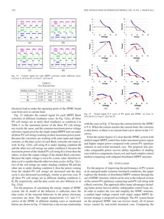
Fig. 8(a) indicates the output I-V and P-V curves of shaded
(red curve) and nonshaded (blue curve) PV cell strings, respec-
tively. Because the voltage reference of the MPP is given by a
single MPPT unit, so the constant power curve of the output of
each SPMC should start at a same voltage value and ending at
current limit of each SPMC as blue and red solid curve shown
in Fig. 8(b). The final voltage reference from the MPPT unit
is neither the MPP of shaded cell string nor the MPP of the
nonshaded PV cell strings, it only stands for a tradeoff state
point where the output power of three parallel PV cell strings
can reach the maximum in a same voltage value as shown in the
enlarged view of the Fig. 8(b), adding the output curve up and
the characteristic curve of the whole SPMC system is shown as
the black curve in Fig. 8(c).
Final comparison is made among aforementioned structures
in Fig. 9. It shows the simulation comparison of the output P-V
curves among the current PV optimizer, the distributed MPPT
6. 1280 IEEE TRANSACTIONS ON POWER ELECTRONICS, VOL. 29, NO. 3, MARCH 2014
Fig. 8. Output I-V and P -V curve of SPMC with proposed control solution. (a) Original PV cell strings. (b) Each MPPT converter. (c) SPMC.
Fig. 9. Comparison of different structure. (a) PV Optimizer. (b) SPMC with distributed MPPT. (c) SPMC with unified MPPT.
SPMC solution, and the proposed unified output MPPT SPMC
solution.
It is obvious that the proposed SPMC system with optimal
single MPPT control has several advantages, both from the the-
oretical and the practical point of view. First, the architecture is
more suitable for power recovery compared with PV optimizer
in real mismatch cases. Second, the power rating of the de-
vice can be reduced to lower level, which is good for efficiency
improvement. And the proposed optimal control approach can
recover more than 90% power loss caused by mismatch case
with less circuit components and lower cost comparing with the
subpanel level distributed MPPT solution.
V. RELIABLE ISSUES OF THE SPMC SYSTEM
The junction box, presented in each standard PV panel, pro-
vides the key bypass functionality (preventing hot-spot phenom-
ena caused by reverse biasing due to defective cells or shading
in traditional PV module). Generally, the bypass diodes inside
the junction box are antiparallel and one-to-one connected to
the subpanel PV cell strings as shown in Fig. 10(a).
Regarding to the system reliability issues, the bypass diodes
inside the junction box of the original PV module should be
retained and antiparallel with the SPMC converter as shown
in Fig. 10(b). Because the output side of a SPMC module-
based PV system is connected with dc nanogrid, to simplify
the analysis for the reliable issues, we assume that a SPMC
module is connecting with a constant voltage source Vout.
Moreover, we need to make statements before the reliable
analysis:
1) the output voltage of each Buck converter inside a SPMC
module is Vo1, Vo2 , and Vo3;
2) the MPP voltage of each PV cell string is VMPPT1,
VMPPT2, VMPPT3;
3) the open circuit voltage of each PV cell string is VOC1,
VOC2, VOC3.
7. WANG et al.: ANALYSIS OF UNIFIED OUTPUT MPPT CONTROL IN SUBPANEL PV CONVERTER SYSTEM 1281
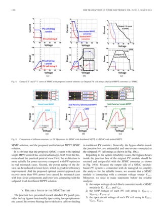
Fig. 10. Structures of standard PV panel and SPMC system. (a) Standard PV
Panel. (b) SPMC Module.
If one of the converters in SPMC, converter #1 for example,
is failed, the analysis can be divided into following three cases:
A. Vout > VOC2+VOC3
In this case, the bypass diode of converter #1 will never con-
duct because the maximum output voltage of the Buck converter
is the open circuit voltage of the PV cell string, so the MPPT
unit loses control in such case.
B. VMPPT2+VMPPT3 < Vout < Vo2+Vo3
In this case, the sum of the output voltages of the remained
normal converters #2 and #3 is slightly larger than the Vout,
so the failed converter is hereby bypassed by the correspond-
ing diode and the Vout also clamps the output voltages of the
converters #2 and #3. As the purpose of the MPPT is keeping
the operating point of the PV cell string always stay on MPP
through the control loop, and the higher output voltage requires
the converters have boost function. So the Buck converters are
working at go-through mode at this time. In this case, the MPPT
unit loses its control and the remaining two PV cell strings can
be seen as connected with the voltage source directly.
C. Vout < VMPPT2+VMPPT3
In this case, the input voltages of converters can be controlled
at MPP through the MPPT control loop and the output voltage
of the remaining two converters #2 and #3 are working toward
another steady-state point if converter #1 is failed. The two
Fig. 11. Experimental prototype.
converters are connecting with the dc bus through the bypass
diode of failed converter #1.
It needs to note that the consideration of the architecture
design of the SPMC-based PV system should be paid more
attention. Especially, the number of the SPMC modules in a
string should be large enough in case the bypass diode of the
failed converter blocks the power flow path. It also affected
by external factors such as the dc bus voltage level, the MPP
parameters of the PV panel, and the irradiance case, etc.
VI. EXPERIMENTAL RESULTS
To verify the SPMC concept and proposed unified MPPT
control strategy, an experimental prototype is constructed
as depicted in Fig. 11. The hardware setup consists of the
following parts.
A. Solar Simulators [40]
For the sources, three E4361 Agilent solar simulators are used
to simulate three PV cell strings inside a standard PV panel. The
solar simulator is capable of quickly simulating the output char-
acteristic curve of PV panels under different irradiance cases
by setting the following parameters: open circuit voltage VOC ;
MPP voltage VMPPT ; short circuit current ISC ; MPP current
IMPPT .
B. SPMC Power Stage
The power stage of the SPMC system is made up of three
synchronous Buck converters with a series connection on the
output side as shown in Fig. 7. The input of each Buck con-
verter has a one-to-one connection with all three E4361 solar
simulators, so the power rating of each buck stage is designed to
meet the power rating of one-third of a PV module. The output
stage of the SPMC was designed with the 9-A current limit and
it is connected with an electrical load.
C. Control Board and Electrical Load
An ALTERA Cyclone III FPGA [41] development board with
corresponding AD9254 and DAC5672IPFBR converters is used
for the single output MPPT realization, which can be taken place
byaMPPTICif mass productionis needed, andall theother con-
trol components are all analog devices due to cost consideration.
The static I-V and P-V curves of the proposed SPMC system
can be derived through adjusting the output current through an
8. 1282 IEEE TRANSACTIONS ON POWER ELECTRONICS, VOL. 29, NO. 3, MARCH 2014
Fig. 12. Control signal for each MPPT converter under different cases.
(a) Case A. (b) Case B. (c) Case C. (d) Case D.
TABLE I
TEST PARAMETERS
electrical load to make the operating point of the SPMC board
scan from zero to current limit.
Fig. 12 indicates the control signal for each MPPT Buck
converter in different irradiance cases. In Fig. 12(a), all three
PV cell strings are in unify ideal irradiance as condition I in
Table I, so the maximum power of the three PV cell strings
are exactly the same, and the common maximum power voltage
reference signal given by the single output MPPT unit can make
all three PV cell strings working on their maximum power point.
Because the converters are working with same input and output
currents, so the duty cycles of each Buck converter are same as
well. In Fig. 12(b), cell string II is under shading condition III
and the other two cell strings are under condition I, because the
maximum power of the shaded PV cell string II is lower than the
others, so does the output voltage of the shaded Buck converter.
Because the input voltage is set to be a same value, therefore its
duty cycle is smaller than the other two duty cycles. In Fig. 12(c),
two of the cell strings are under shading condition III and the
other one is under shading condition I, then the power coming
from the shaded PV cell strings are decreased and the duty
cycle is also decreased accordingly, similar as previous case. If
all three PV cell strings are in different shading conditions I,
II, III, respectively, and the duty cycles are also different as in
Fig. 12(d).
For the purposes of calculating the energy output of SPMC
system, the dc model of the behavior is sufficient since the
time-scales of the transient behaviors in the power electronic
converters are short. The output characteristic I-V and P-V
curves of the SPMC in different shading cases as mentioned
before are shown in Fig. 13 which has a one-to-one relationship
Fig. 13. Tested output P–V curve of PV panel and SPMC. (a) Case A.
(b) Case B. (c) Case C. (d) Case D.
with the cases in Fig. 12 because the current limit for the SPMC
is 9 A. When the current reaches the current limit, the converter
is shut down, so there is no current limit curve shown in the I-V
curves.
From the earlier figures it’s clear that the SPMC system with
unified output MPPT control has wider maximum power region
and higher output power compared with current PV optimizer
solution in real-world mismatch case. The proposal also pro-
vides comparable power recover ability regardless of shading
case with less components, lower cost, and much simpler control
method comparing with subpanel distributed MPPT structure.
VII. CONCLUSION
For the purpose of improving the performance of PV system
in dc nanogrid under common mismatch conditions, this paper
explores the benefits of distributed MPPT solution through the
use of SPMC structure, which can be seen as the reduced version
of the current PV optimizer, connecting each PV cell string with
a Buck converter. The approach offers many advantages includ-
ing better power harvest ability, independent control loop, etc.
In order to reduce the cost and simplify the SPMC structure,
a unified input voltage control with single output MPPT de-
tection strategy is proposed accordingly. The PV system based
on the proposed SPMC unit can recover nearly all of power
losses caused by real-world mismatch case. Comparing the
9. WANG et al.: ANALYSIS OF UNIFIED OUTPUT MPPT CONTROL IN SUBPANEL PV CONVERTER SYSTEM 1283
distributed MPPT control structure with the SPMC PV system,
this simplified control approach offers a number of additional
practical implementation advantages such as: saves the number
of A/D units, current sensors, and MPPT controllers units on the
premise of guaranteeing maximum power statue regardless of
the mismatch case. The simulation and experimental results ver-
ify that the proposed SPMC with unified output MPPT control
solution exhibits good performance under inhomogeneous and
homogeneous irradiations with an enhancement rate of about
20% in power harvest.
Future work will envisage a deeper study of the distributed
MPPT converter-based PV systems in order to better justify the
approach from a theoretical viewpoint. Possible extensions to
other types of SPMC topologies are also of interest.
REFERENCES
[1] D. Boroyevich, I. Cvetkovic, D. Dong, R. Burgos, W. Fei, and F. Lee,
“Future electronic power distribution systems a contemplative view,” in
Proc. 12th Int. Conf. Optim. Electr. Electron. Equipment, 2010, pp. 1369–
1380.
[2] D. Dong, T. Thacker, I. Cvetkovic, R. Burgos, D. Boroyevich, F. Wang,
and G. Skutt, “Modes of operation and system-level control of single-
phase bidirectional PWM converter for microgrid systems,” IEEE Trans.
Smart Grid, vol. 3, no. 1, pp. 93–104, Mar. 2012.
[3] D. Dong, L. Fang, Z. Wei, D. Boroyevich, P. Mattavelli, I. Cvetkovic,
J. Li, and K. Pengju, “Passive filter topology study of single-phase ac-dc
converters for DC nanogrid applications,” in Proc. IEEE 26th Annu. Appl.
Power Electron. Conf. Expo., 2011, pp. 287–294.
[4] S. M. MacAlpine, R. W. Erickson, and M. J. Brandemuehl, “Character-
ization of power optimizer potential to increase energy capture in pho-
tovoltaic systems operating under nonuniform conditions,” IEEE Trans.
Power Electron., vol. 28, no. 6, pp. 2936–2945, Jun. 2013.
[5] E. V. Paraskevadaki and S. A. Papathanassiou, “Evaluation of MPP volt-
age and power of mc-Si PV modules in partial shading conditions,” IEEE
Trans. Energy Convers., vol. 26, no. 3, pp. 923–932, Sep. 2011.
[6] J. Wohlgemuth and W. Herrmann, “Hot spot tests for crystalline silicon
modules,” in Proc. IEEE 31st Conf. Rec. Photovolt. Spec., 2005, pp. 1062–
1063.
[7] H. Patel and V. Agarwal, “MATLAB-based modeling to study the effects of
partial shading on PV array characteristics,” IEEE Trans. Energy Convers.,
vol. 23, no. 1, pp. 302–310, Mar. 2008.
[8] G. Carannante, C. Fraddanno, M. Pagano, and L. Piegari, “Experimen-
tal performance of MPPT algorithm for photovoltaic sources subject to
inhomogeneous insolation,” IEEE Trans. Ind. Electron., vol. 56, no. 11,
pp. 4374–4380, Nov. 2009.
[9] S. Kazmi, H. Goto, O. Ichinokura, and G. Hai-Jiao, “An improved and
very efficient MPPT controller for PV systems subjected to rapidly varying
atmospheric conditions and partial shading,” in Proc. Power Eng. Conf.,
2009, pp. 1–6.
[10] H. Patel and V. Agarwal, “Maximum power point tracking scheme for PV
systems operating under partially shaded conditions,” IEEE Trans. Ind.
Electron., vol. 55, no. 4, pp. 1689–1698, Apr. 2008.
[11] B. N. Alajmi, K. H. Ahmed, S. J. Finney, and B. W. Williams, “A maxi-
mum power point tracking technique for partially shaded photovoltaic sys-
tems in microgrids,” IEEE Trans. Ind. Electron., vol. 60, no. 4, pp. 1596–
1606, Apr. 2013.
[12] E. Koutroulis and F. Blaabjerg, “A new technique for tracking the global
maximum power point of PV arrays operating under partial-shading con-
ditions,” IEEE J. Photovolt., vol. 2, no. 2, pp. 184–190, Apr. 2012.
[13] N. Femia, G. Petrone, G. Spagnuolo, and M. Vitelli, “Optimization of
perturb and observe maximum power point tracking method,” IEEE Trans.
Power Electron., vol. 20, no. 4, pp. 963–973, Jul. 2005.
[14] J. Young-Hyok, J. Doo-Yong, K. Jun-Gu, K. Jae-Hyung, L. Tae-Won, and
W. Chung-Yuen, “A real maximum power point tracking method for mis-
matching compensation in PV array under partially shaded conditions,”
IEEE Trans. Power Electron., vol. 26, no. 4, pp. 1001–1009, Apr. 2011.
[15] R. Alonso, E. Roman, A. Sanz, V. E. M. Santos, and P. Ibanez, “Analysis of
inverter-voltage influence on distributed MPPT architecture performance,”
IEEE Trans. Ind. Electron., vol. 59, no. 10, pp. 3900–3907, Oct. 2012.
[16] N. Femia, G. Lisi, G. Petrone, G. Spagnuolo, and M. Vitelli, “Distributed
maximum power point tracking of photovoltaic arrays: novel approach
and system analysis,” IEEE Trans. Ind. Electron., vol. 55, no. 7, pp. 2610–
2621, Jul. 2008.
[17] L. Linares, R. W. Erickson, S. MacAlpine, and M. Brandemuehl, “Im-
proved energy capture in series string photovoltaics via smart distributed
power electronics,” in Proc. IEEE 24th Annu. Appl. Power Electron. Conf.
Expo., 2009, pp. 904–910.
[18] G. R. Walker and P. C. Sernia, “Cascaded DC-DC converter connection
of photovoltaic modules,” IEEE Trans. Power Electron., vol. 19, no. 4,
pp. 1130–1139, Jul. 2004.
[19] L. Bangyin, D. Shanxu, and C. Tao, “Photovoltaic DC-building-module-
based BIPV system—Concept and design considerations,” IEEE Trans.
Power Electron., vol. 26, no. 5, pp. 1418–1429, May 2011.
[20] S. Vighetti, J. P. Ferrieux, and Y. Lembeye, “Optimization and design
of a cascaded DC/DC converter devoted to grid-connected photovoltaic
systems,” IEEE Trans. Power Electron., vol. 27, no. 4, pp. 2018–2027,
Apr. 2012.
[21] L. Zhigang, G. Rong, L. Jun, and A. Q. Huang, “A high-efficiency PV
module-integrated DC/DC converter for PV energy harvest in FREEDM
systems,” IEEE Trans. Power Electron., vol. 26, no. 3, pp. 897–909, Mar.
2011.
[22] Y. Wei, G. Mingzhi, R. Zheng, C. Min, and Q. Zhaoming, “Improvement
of performance and flexibility for photovoltaic module using individual
DC/DC converter,” in Proc. IEEE 6th Int. Power Electron. Motion Control
Conf., 2009, pp. 441–444.
[23] P. Tsao, “Simulation of PV systems with power optimizers and distributed
power electronics,” in Proc. IEEE 35th Photovolt. Spec. Conf., 2010,
pp. 000389–000393.
[24] P. Tsao, S. Sarhan, and I. Jorio, “Distributed max power point tracking
for photovoltaic arrays,” in Proc. IEEE 34th Photovolt. Spec. Conf., 2009,
pp. 002293–002298.
[25] G. Adinolfi, N. Femia, G. Petrone, G. Spagnuolo, and M. Vitelli, “Energy
efficiency effective design of DC/DC converters for DMPPT PV applica-
tions,” in Proc. IEEE 35th Annu. Ind. Electron., 2009, pp. 4566–4570.
[26] C. Yaow-Ming, C. Cheng-Wei, and C. Yang-Lin, “Development of an
autonomous distributed maximum power point tracking PV system,” in
Proc. IEEE Energy Convers. Congr. Expo., 2011, pp. 3614–3619.
[27] R. Alonso, P. Ib´a˜nez, V. Martinez, E. Roman, and A. Sanz, “Analysis of
performance of new distributed MPPT architectures,” in Proc. IEEE Int.
Symp. Ind. Electron., 2010, pp. 3450–3455.
[28] X. Weidong, N. Ozog, and W. G. Dunford, “Topology study of photo-
voltaic interface for maximum power point tracking,” IEEE Trans. Ind.
Electron., vol. 54, no. 3, pp. 1696–1704, Jun. 2007.
[29] C. Deline, B. Marion, J. Granata, and S. Gonzalez. (2011, Jan.). A
performance and economic analysis of distributed power electronics in
photovoltaic systems. Techn. Rep. [Online]. Available: http://www.nrel.
gov/docs/fy11osti/50003.pdf
[30] (2011, Mar. 7). AN-2120 power optimizers partial deployment for sin-
gle string systems. Appl. Rep. [Online]. Available: http://www.ti.com/
lit/an/snosb67b/snosb67b.pdf
[31] S. V. Dhople, J. L. Ehlmann, A. Davoudi, and P. L. Chapman, “Multiple-
input boost converter to minimize power losses due to partial shading
in photovoltaic modules,” in Proc. IEEE Energy Convers. Congr. Expo.,
2010, pp. 2633–2636.
[32] C. Olalla, D. Clement, M. Rodriguez, and D. Maksimovic, “Architectures
and control of submodule integrated DC-DC converters for photovoltaic
applications,” IEEE Trans. Power Electron., vol. 28, no. 6, pp. 2980–2997,
Jun. 2013.
[33] R. C. N. Pilawa-Podgurski and D. J. Perreault, “Submodule integrated
distributed maximum power point tracking for solar photovoltaic applica-
tions,” IEEE Trans. Power Electron., vol. 28, no. 6, pp. 2957–2967, Jun.
2013.
[34] P. Wolfs, “Device for distributed maximum power tracking for solar array,”
U.S. Patent 8093757B2, Dec. 2008.
[35] S. Poshtkouhi and O. Trescases, “Multi-input single-inductor dc-dc con-
verter for MPPT in parallel-connected photovoltaic applications,” in Proc.
IEEE 26th Annu. Appl. Power Electron. Conf. Expo., 2011, pp. 41–47.
[36] R. C. N. Pilawa-Podgurski, N. A. Pallo, W. R. Chan, D. J. Perreault, and
I. L. Celanovic, “Low-power maximum power point tracker with digital
control for thermophotovoltaic generators,” in Proc. IEEE 25th Annu.
Appl. Power Electron. Conf. Expo., 2010, pp. 961–967.
[37] J. Stauth, M. Seeman, and K. Kesarwani, “A high-voltage CMOS IC and
embedded system for distributed photovoltaic energy optimization with
over 99% effective conversion efficiency and insertion loss below 0.1%,”
10. 1284 IEEE TRANSACTIONS ON POWER ELECTRONICS, VOL. 29, NO. 3, MARCH 2014
in Proc. IEEE Int. Solid-State Circuits Conf. Dig. Tech. Papers, 2012,
pp. 100–102.
[38] D. Shmilovitz, “On the control of photovoltaic maximum power point
tracker via output parameters,” in Proc. IEE Electr. Power Appl., vol. 152,
pp. 239–248, 2005.
[39] S. Poshtkouhi, J. Varley, R. Popuri, and O. Trescases, “Analysis of dis-
tributed peak power tracking in photovoltaic systems,” in Proc. Int. Power
Electron. Conf., 2010, pp. 942–947.
[40] L. Nousiainen, J. Puukko, A. Maki, T. Messo, J. Huusari, J. Jokipii,
J. Viinamaki, D. T. Lobera, S. Valkealahti, and T. Suntio, “Photovoltaic
generator as an input source for power electronic converters,” IEEE Trans.
Power Electron., vol. 28, no. 6, pp. 3028–3038, Jun. 2013.
[41] (2011). Cyclone III device handbook. Altera Corporation. [Online]. 1.
Available: http://www.altera.com/literature/hb/cyc3/cyc3_ciii5v1.pdf
Feng Wang (S’08) received the B.S. and M.S. de-
grees in electrical engineering from Xi’an Jiaotong
University, Xi’an, China, in 2005 and 2009, respec-
tively, where he is currently working toward the Ph.D.
degree in electrical engineering. From 2010 to 2012,
he was an exchange Ph.D. student in the Center for
Power Electronics Systems, Virginia Polytechnic In-
stitute and State University, Blacksburg, USA.
He is currently with the State Key Laboratory of
Electrical Insulation and Power Equipment, School
of Electrical Engineering, Xian Jiaotong University
and also with the Center for Power Electronics Systems, Virginia Polytechnic
Institute and State University. His research interests include dc/dc conversion,
digital control of switched converters, especially in distributed renewable en-
ergy generation fields.
Xinke Wu (AM’09–M’10) received the B.S. and
M.S. degrees in electrical engineering from the
Harbin Institute of Technology, Harbin, China, in
2000 and 2002, respectively, and the Ph.D. degree
in electrical engineering from Zhejiang University,
Hangzhou, China, in 2006.
From 2007 to 2009, he was a Postdoctoral Fel-
low in the National Engineering Research Center for
Applied Power Electronics, Zhejiang University, and
from 2009 to 2010 he was an Assistant Research Fel-
low. From 2011 to 2012, he was a Visiting Scholar
in the Center of Power Electronics System, Virginia Tech. Since 2011, he has
been an Associate Professor of electrical engineering with Zhejiang Univer-
sity. His research interests include high efficiency LED driving technology, soft
switching and high efficiency power conversion, and power electronics system
integration.
Dr. Wu was awarded as Distinguished Young Scholar of Zhejiang University
in 2012.
Fred C. Lee (S’72–M’74–SM’87–F’90) received the
B.S. degree in electrical engineering from National
Cheng Kung University, Tainan, Taiwan, in 1968, and
the M.S. and Ph.D. degrees in electrical engineering
from Duke University, Durham, NC, USA, in 1972
and 1974, respectively.
He is currently an University Distinguished Pro-
fessor with Virginia Polytechnic Institute and State
University (Virginia Tech), Blacksburg, USA. He di-
rects the Center for Power Electronics Systems, a
National Science Foundation Engineering Research
Center. He is the holder of 35 U.S. patents and has published more than 200 jour-
nal articles and more than 500 technical papers in conference proceedings. His
research interests include high-frequency power conversion, distributed power
systems, electronic packaging, and modeling and control.
Zijian Wang (M’08) received the B.S. degree
in electrical engineering from Zhejiang University,
Hangzhou, China, in 2006. He received the M.S.
degree in electrical engineering from Virginia Tech,
Blacksburg, VA, USA, in 2010. Since 2007, he has
been working toward the Ph.D. degree in the Center
for Power Electronics Systems, Virginia Polytechnic
Institute and State University.
From October 2011 to February 2013, he worked
as the Applications Engineer in Monolithic Power
Systems, Inc. Since March 2013, he has been work-
ing as the Applications Engineer in Linear Technology Corporation, CA, USA.
His research interests include power factor correction converters, electromag-
netic interference modeling, and design optimization.
Pengju Kong (M’08) received the B.S. and Ph.D.
degrees in electrical engineering from Tsinghua
University, Beijing, China, in 2003 and 2009,
respectively.
Between 2005 and 2009, he was a Visiting Scholar
at Center for Power Electronics Systems (CPES),
Virginia Polytechnic Institute and State University,
Blacksburg, VA, USA. He continued his research in
CPES as a Postdoctoral Associate after receiving the
Ph.D. degree. He joined iWatt., Inc., Campbell, CA,
USA, as a System and Application Engineer. His
research interests include EMI modeling and reduction techniques in power
electronics systems, power factor correction techniques, high-frequency dc/dc
converter, photovoltaic converter, and modeling and control of converters.
Fang Zhuo (M’00) received the B.S., M.S., and Ph.D.
degrees in electrical engineering from Xi’an Jiaotong
University, Xi’an, China, in 1984, 1989, and 2001,
respectively.
In 1984, he was a Lecturer at Xi’an Jiaotong Uni-
versity, an Associate Professor in 1996, and a Full
Professor in power electronics and drives in 2004. In
2004, he worked as a Visiting Scholar in Nanyang
Technological University, Singapore. He was a
Supervisor of Ph.D. student in 2006. He has pub-
lished 160 articles, more than 30 papers were indexed
by SCI, EI, and ISTP, and he is also the coauthor of two handbooks, and holds
four patents. He is the Power Quality Professional Chairman of Power Supply
Society of China. His research interests include motor driver control, power
quality improvement, grid-connected renewable energy system, and microgrid.