Download to read offline
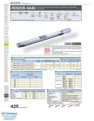
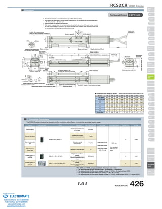

This document provides specifications for the RCS2CR-SA4C cleanroom ROBO cylinder slider coupling actuator. It includes details on: - Actuator specifications like stroke lengths from 50-400mm, lead sizes of 10, 5, or 2.5mm, load capacities, and maximum speeds. - Options available like brakes, foot brackets, and different cable lengths. - Dimensions and weights that vary by stroke length. - Compatible controllers for operating the actuators, including models for position and program control with 1-6 axes and pulse train or serial communication input.


