Download to read offline

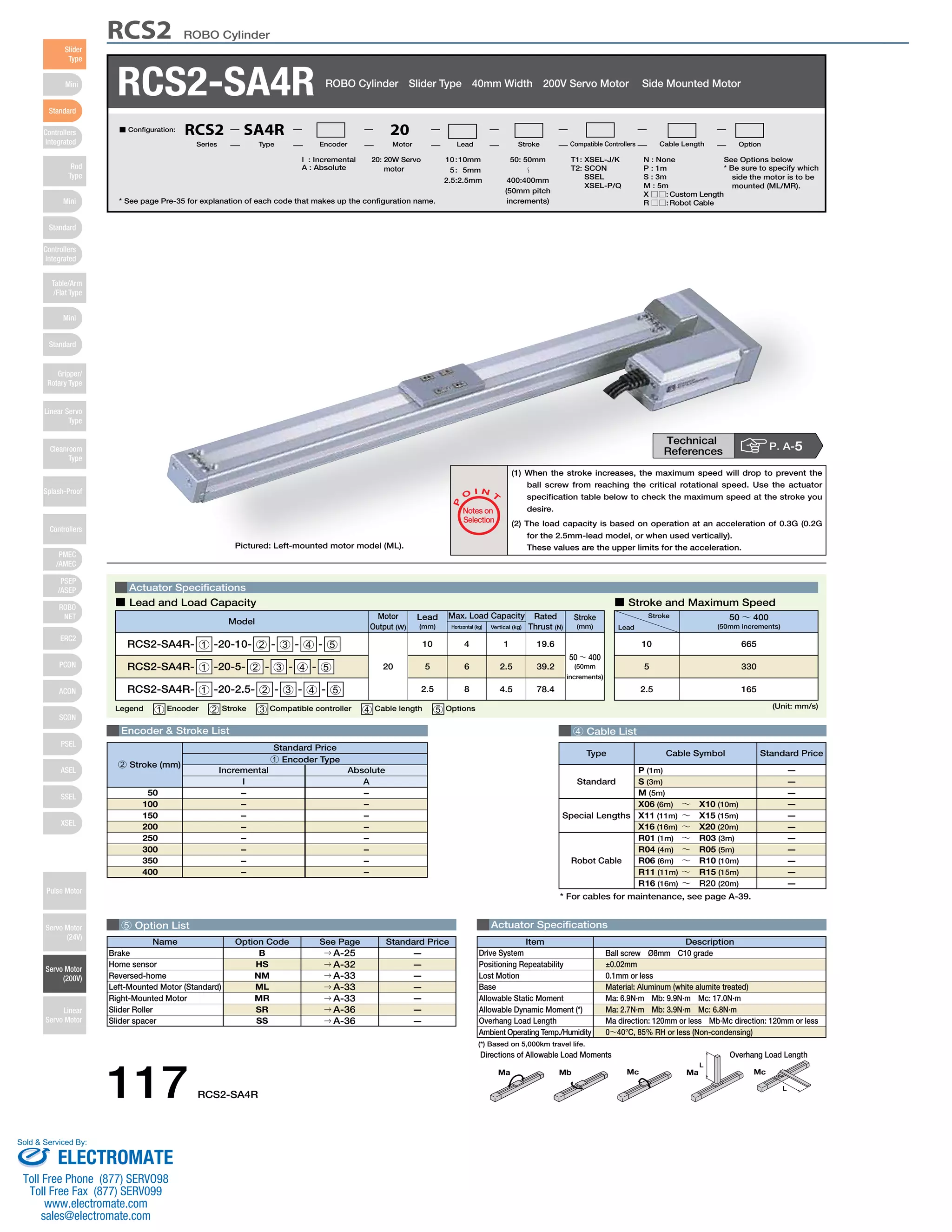
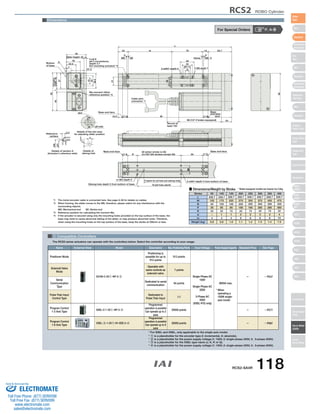

The document provides specifications for the RCS2-SA4R ROBO Cylinder actuator. It includes details on the actuator such as maximum load capacity, stroke length, speed, and dimensions for different stroke lengths. Compatible controllers that can operate the actuator are also listed, including the SCON, SSEL, and XSEL controllers.


