Download to read offline

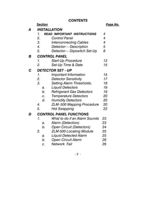
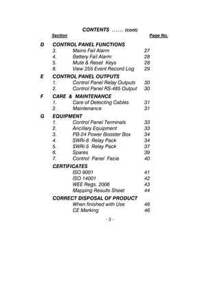
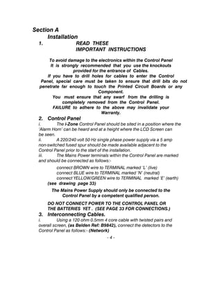
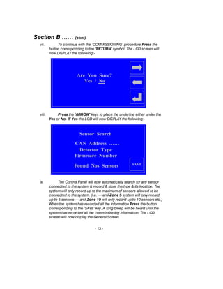
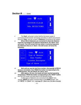
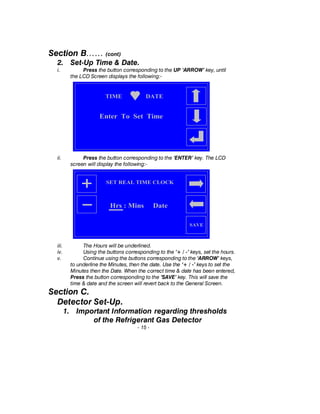
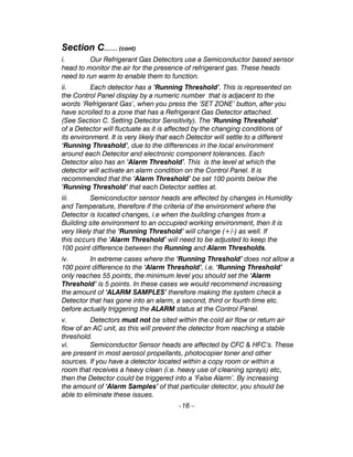


This document provides installation, setup, and operating instructions for an environmental monitoring system called the 'Aqualarm'. It includes sections on installing the control panel, detectors, and interconnecting cables. It describes the various types of detectors available (such as water, temperature, humidity, etc.) and how to set their sensitivity thresholds and map the water leak locating module. The document also covers control panel functions like viewing alarms, outputs, maintenance, and specifications of equipment. It provides certificates and instructions for proper disposal of the system.


