Download to read offline
![SUBMITTED BY
NAME - SOUMYA SHARMA
COURSE- BACHELOR OF INTERIOR DESIGN ( 7th SEMESTER)
BATCH - 2017-21
ENR. NO. - A8380317012
INTELLIGENT INTERIORS [ COURSE CODE : ID335 ]
SUBMITTED TO : MS. SUPARNA SIRCAR](https://image.slidesharecdn.com/firesafetysoumya-201221124438/85/Fire-Safety-Devices-Fire-detection-systems-1-320.jpg)
![SUBMITTED BY
NAME - SOUMYA SHARMA
COURSE- BACHELOR OF INTERIOR DESIGN ( 7th SEMESTER)
BATCH - 2017-21
ENR. NO. - A8380317012
INTELLIGENT INTERIORS [ COURSE CODE : ID335 ]
SUBMITTED TO : MS. SUPARNA SIRCAR](https://image.slidesharecdn.com/firesafetysoumya-201221124438/75/Fire-Safety-Devices-Fire-detection-systems-1-2048.jpg)


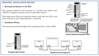
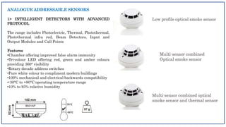
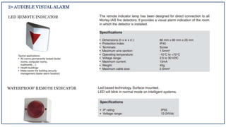

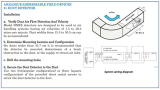


The document is a submission for an interior design course that summarizes intelligent interior products from Morley-IAS, including their fire alarm control panels, repeaters, sensors, audible/visual alarms, beam detectors, duct detectors, and a radio detection interface module. It provides details on the company's history and product lines. Key information discussed includes installation and wiring of control panels and repeaters, features of intelligent detectors and sensors, and duct detector installation procedures.