Download to read offline
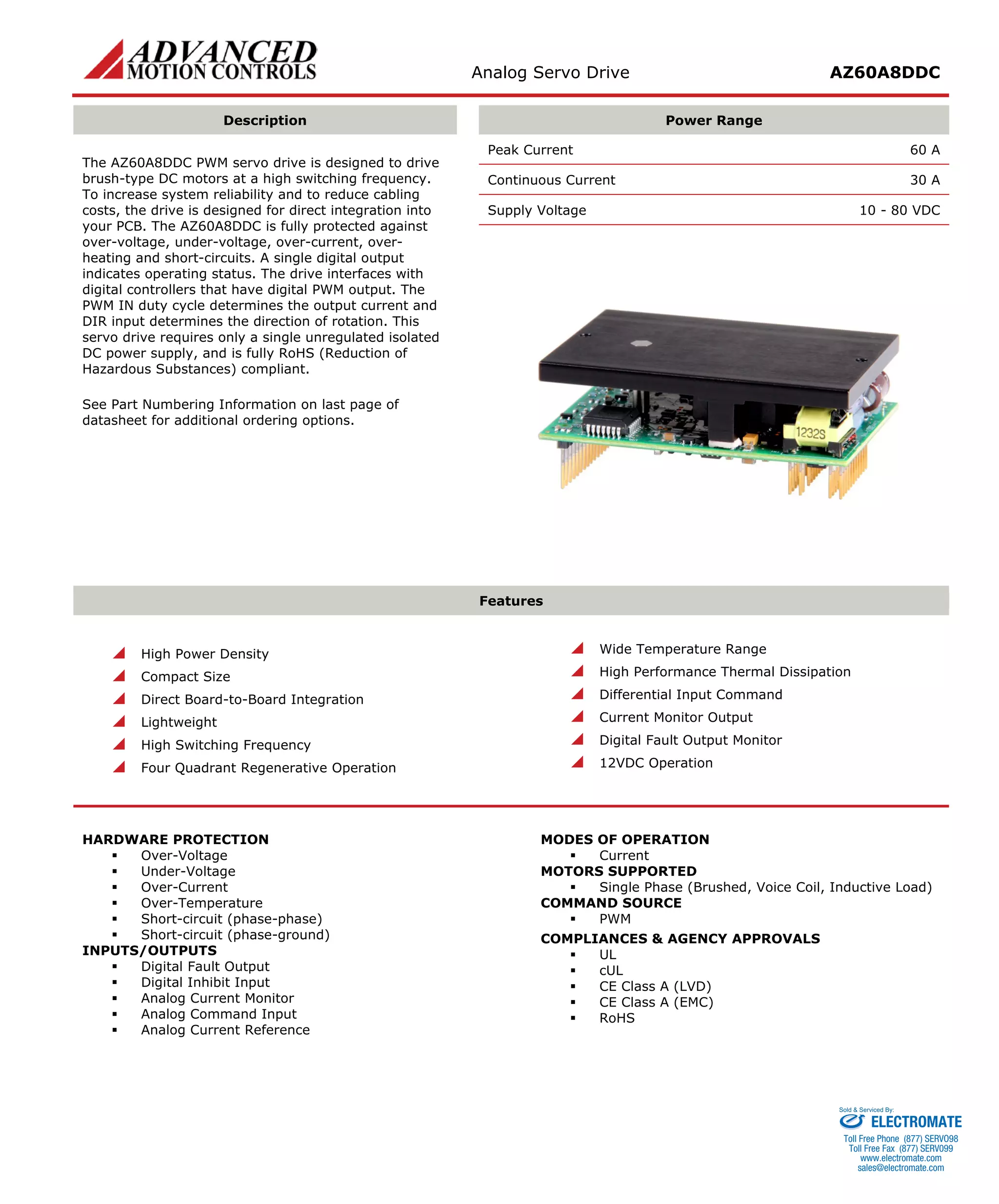
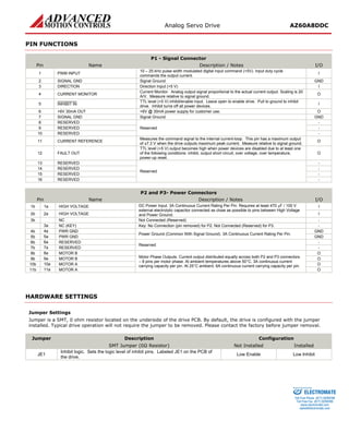

The AZ60A8DDC is a PWM servo drive designed to drive brush-type DC motors at high switching frequencies. It has a peak current of 60A, continuous current of 30A, and operates from 10-80VDC. The drive provides motor control and protection from overvoltage, undervoltage, overcurrent and more.


![Getting Started with Apache Spark: Big Data Made Simple [Free Meetup]](https://cdn.slidesharecdn.com/ss_thumbnails/apachesparkgettingstarted-260203175547-8361bcc3-thumbnail.jpg?width=640&height=640&fit=bounds)


