The document discusses material handling equipment and fluid power systems. It provides an introduction to different types of material handling equipment, including storage and handling equipment, engineered systems, industrial trucks, and bulk material handling. It also discusses the basic principles of hydraulics and pneumatics, describing how hydraulic and pneumatic systems can be used to transmit power and convert it to linear or rotary motion using actuators like hydraulic cylinders. Specific components of hydraulic systems are outlined, including pumps, cylinders, valves, and reservoirs.
This presentation contains:
1. Types of FLT
2. Specifications of FLT
3. Capacity rating of FLT
4. Turning Radius and Aisle Width
5. FLT Attachments
6. Power Rating Calculations for FLT
7. Battery rating & Selection
8. Energy calculation
Find Lecture Videos on my youtube channel -> https://www.youtube.com/channel/UC1mGQxcNkyUjoQIYZaSFtPQ?view_as=subscriber
DESIGN AND DEVELOPMENT OF A TRANSMISSION SYSTEM FOR AN ALL TERRAIN VEHICLEIAEME Publication
The main function of a transmission system is to transfer the required torque and power generated by the engine to the wheels as and when required by the driver. In automobiles this is done with the help of a gearbox and a final drive alternative. The objective of this work is to design and develop a transmission system which is reliable, safe and cost effective. It should be able to transmit sufficient power and torque to generate the required traction at the wheels at any particular rpm. As the vehicle under consideration is an All-Terrain Vehicle (ATV), which is subjected to varying and rugged road conditions, the power transmission should be constant and uninterrupted.
CATERPILLAR CAT DP70 FORKLIFT LIFT TRUCKS Service Repair Manual SN:T20C-60001...jsenmde8udj
This is the Highly Detailed factory service repair manual for theCATERPILLAR CAT DP70 FORKLIFT LIFT TRUCKS, this Service Manual has detailed illustrations as well as step by step instructions,It is 100 percents complete and intact. they are specifically written for the do-it-yourself-er as well as the experienced mechanic.CATERPILLAR CAT DP70 FORKLIFT LIFT TRUCKS Service Repair Workshop Manual provides step-by-step instructions based on the complete dis-assembly of the machine. It is this level of detail, along with hundreds of photos and illustrations, that guide the reader through each service and repair procedure. Complete download comes in pdf format which can work under all PC based windows operating system and Mac also, All pages are printable. Using this repair manual is an inexpensive way to keep your vehicle working properly.
Service Repair Manual Covers:
Chassis, Mast and Attachments: Foreword
Chassis, Mast and Attachments: General Information
Chassis, Mast and Attachments: Cooling System
Chassis, Mast and Attachments: Electrical System
Chassis, Mast and Attachments: Electrical System - Schematics
Chassis, Mast and Attachments: Power Train
Chassis, Mast and Attachments: Power shift Transmission
Chassis, Mast and Attachments: Front Axle and Reduction Differential
Chassis, Mast and Attachments: Rear Axle
Chassis, Mast and Attachments: Brake System
Chassis, Mast and Attachments: Steering System
Chassis, Mast and Attachments: Hydraulic System
Chassis, Mast and Attachments: Mast and Forks
Chassis, Mast and Attachments: Fork Positioner
Chassis, Mast and Attachments: Side Shifter
Chassis, Mast and Attachments: Service Data
S6S Diesel Engine: General
S6S Diesel Engine: Maintenance Standards
S6S Diesel Engine: Special Tools
S6S Diesel Engine: Overhaul Instructions
S6S Diesel Engine: Adjustments, Bench Test, Performance Tests
S6S Diesel Engine: Engine Auxiliaries Removal and Installation
S6S Diesel Engine: Engine Main Parts
S6S Diesel Engine: Inlet and Exhaust System
S6S Diesel Engine: Lubrication System
S6S Diesel Engine: Cooling System
S6S Diesel Engine: Fuel System
S6S Diesel Engine: Electrical System
S6S Diesel Engine: Workshop Tips
File Format: PDF
Compatible: All Versions of Windows & Mac
Language: English
Requirements: Adobe PDF Reader
NO waiting, Buy from responsible seller and get INSTANT DOWNLOAD, Without wasting your hard-owned money on uncertainty or surprise! All pages are is great to haveCATERPILLAR CAT DP70 FORKLIFT LIFT TRUCKS Service Repair Workshop Manual.
Looking for some other Service Repair Manual,please check:
https://www.aservicemanualpdf.com/
Thanks for visiting!
8
Abstract:
Landing gear is one of the critical subsystems of an aircraft. The need to design landing gear with minimum weight, minimum volume, high performance, improved life and reduced life cycle cost have posed many challenges to landing gear designers and practitioners. Further it is essential to reduce the landing gear design and development cycle time while meeting all the regulatory and safety requirements. Many technologies have been developed over the years to meet these challenges in design and development of landing gear. This paper presents a perspective on various stages of landing gear design and development, current technology landscape and how these technologies are helping us to meet the challenges involved in the development of landing gear and how they are going to evolve in future.
NAME : S. Srinivasa Phani Kumar
Branch : MECHANICAL
College : SWARNANDHRA COLLEGE OF ENGINEERING & TECHNOLOGY
Presentation includes working principle of waterjet propulsion, geometry of the components and the Pro's and cons of the system along with the hintory of the system.
A clutch is a mechanism which enables the rotary motion of one shaft to be transmitted at will to the second shaft, whose axis is coincident with that of first. Clutch is located between the engine and gearbox. When the clutch is engaged, the power flows from the engine to the rear wheels through the transmission system and the vehicle moves when the clutch is disengaged, the power is not transmitted to the rear wheels and the vehicle stops, while the engine is still running.
Caterpillar Cat DP30N Forklift Lift Trucks Service Repair Manual SN:T14E-4000...ukejkmd
This is the Highly Detailed factory service repair manual for theCATERPILLAR CAT DP30N FORKLIFT LIFT TRUCKS, this Service Manual has detailed illustrations as well as step by step instructions,It is 100 percents complete and intact. they are specifically written for the do-it-yourself-er as well as the experienced mechanic.CATERPILLAR CAT DP30N FORKLIFT LIFT TRUCKS Service Repair Workshop Manual provides step-by-step instructions based on the complete dis-assembly of the machine. It is this level of detail, along with hundreds of photos and illustrations, that guide the reader through each service and repair procedure. Complete download comes in pdf format which can work under all PC based windows operating system and Mac also, All pages are printable. Using this repair manual is an inexpensive way to keep your vehicle working properly.
Service Repair Manual Covers:
Chassis and Mast: Foreword
Chassis and Mast: General Information
Chassis and Mast: Cooling System
Chassis and Mast: Electrical System
Chassis and Mast: Electrical System-Schematics
Chassis and Mast: Controllers
Chassis and Mast: Power Train
Chassis and Mast: Clutches
Chassis and Mast: Manual Transmission
Chassis and Mast: Power shift Transmission
Chassis and Mast: Front Axle and Reduction Differential
Chassis and Mast: Rear Axle
Chassis and Mast: Brake System
Chassis and Mast: Steering System
Chassis and Mast: Hydraulic System
Chassis and Mast: Mast and Forks
Chassis and Mast: Service Data
S4S Diesel Engine: General Information
S4S Diesel Engine: Maintenance Standards
S4S Diesel Engine: Special Tools
S4S Diesel Engine: General Instructions
S4S Diesel Engine: Disassembly and Engine Main Parts
S4S Diesel Engine: Inspection and Repair, Engine Main Parts
S4S Diesel Engine: Reassembly, Engine Main Parts
S4S Diesel Engine: Fuel System
S4S Diesel Engine: Lubrication System
S4S Diesel Engine: Cooling System
S4S Diesel Engine: Inlet and Exhaust System
S4S Diesel Engine: Electrical System
S4S Diesel Engine: Adjustment, Bench Test, Performance Tests
S4S Diesel Engine: Troubleshooting
File Format: PDF
Compatible: All Versions of Windows & Mac
Language: English
Requirements: Adobe PDF Reader
NO waiting, Buy from responsible seller and get INSTANT DOWNLOAD, Without wasting your hard-owned money on uncertainty or surprise! All pages are is great to haveCATERPILLAR CAT DP30N FORKLIFT LIFT TRUCKS Service Repair Workshop Manual.
Looking for some other Service Repair Manual,please check:
https://www.aservicemanualpdf.com/
Thanks for visiting!
8
Material handling equipment (MHE) is an essential mechanical equipment responsible for the movement, storage, control and protection of business productions. From manufacturing, distribution, and consumption to disposal, buy MHE supplies online does everything.
A dock leveler, also known as a loading dock leveler, is a piece of equipment used to bridge the height difference and create a smooth transition between a loading dock and a truck or trailer bed. Loading docks are raised platforms in warehouses or distribution centers where trucks can be loaded and unloaded.
Introduction
Types of Material Handling Equipment
Material Transport Equipment
Storage Systems
Unitizing Equipment
Identification and Tracking Systems
Principles of Material Handling
Automated Guided Vehicles (AGVs)
Components of AGVS
Types of AGVs
Driverless Trains
Automated Guided Pallet Trucks
AGV Unit Load Carriers
Vehicle Guidance
Imbedded Guide Wires
Paint Strips
Self-guided Vehicles
Vehicle Routing
Frequency Select Method
Path Switch Select Method
Traffic Control
On-board Vehicle Sensing
Zone Control
Benefits of AGV
Applications of AGV
An In-Depth Look at the Structure and Mechanism of the Hydraulic Scissor Lift...Nilkamal Material Handling
How exactly does the hydraulic scissor lift table work, and what does its structure entail? Here’s a look. Visit http://nilkamalmaterialhandling.com/ to know more!
The movement, storage, protection and control of materials throughout the manufacturing and distribution process including their consumption and disposal.
Automated Guided Vehicles and so on.
Saudi Arabia stands as a titan in the global energy landscape, renowned for its abundant oil and gas resources. It's the largest exporter of petroleum and holds some of the world's most significant reserves. Let's delve into the top 10 oil and gas projects shaping Saudi Arabia's energy future in 2024.
NO1 Uk best vashikaran specialist in delhi vashikaran baba near me online vas...Amil Baba Dawood bangali
Contact with Dawood Bhai Just call on +92322-6382012 and we'll help you. We'll solve all your problems within 12 to 24 hours and with 101% guarantee and with astrology systematic. If you want to take any personal or professional advice then also you can call us on +92322-6382012 , ONLINE LOVE PROBLEM & Other all types of Daily Life Problem's.Then CALL or WHATSAPP us on +92322-6382012 and Get all these problems solutions here by Amil Baba DAWOOD BANGALI
#vashikaranspecialist #astrologer #palmistry #amliyaat #taweez #manpasandshadi #horoscope #spiritual #lovelife #lovespell #marriagespell#aamilbabainpakistan #amilbabainkarachi #powerfullblackmagicspell #kalajadumantarspecialist #realamilbaba #AmilbabainPakistan #astrologerincanada #astrologerindubai #lovespellsmaster #kalajaduspecialist #lovespellsthatwork #aamilbabainlahore#blackmagicformarriage #aamilbaba #kalajadu #kalailam #taweez #wazifaexpert #jadumantar #vashikaranspecialist #astrologer #palmistry #amliyaat #taweez #manpasandshadi #horoscope #spiritual #lovelife #lovespell #marriagespell#aamilbabainpakistan #amilbabainkarachi #powerfullblackmagicspell #kalajadumantarspecialist #realamilbaba #AmilbabainPakistan #astrologerincanada #astrologerindubai #lovespellsmaster #kalajaduspecialist #lovespellsthatwork #aamilbabainlahore #blackmagicforlove #blackmagicformarriage #aamilbaba #kalajadu #kalailam #taweez #wazifaexpert #jadumantar #vashikaranspecialist #astrologer #palmistry #amliyaat #taweez #manpasandshadi #horoscope #spiritual #lovelife #lovespell #marriagespell#aamilbabainpakistan #amilbabainkarachi #powerfullblackmagicspell #kalajadumantarspecialist #realamilbaba #AmilbabainPakistan #astrologerincanada #astrologerindubai #lovespellsmaster #kalajaduspecialist #lovespellsthatwork #aamilbabainlahore #Amilbabainuk #amilbabainspain #amilbabaindubai #Amilbabainnorway #amilbabainkrachi #amilbabainlahore #amilbabaingujranwalan #amilbabainislamabad
Water scarcity is the lack of fresh water resources to meet the standard water demand. There are two type of water scarcity. One is physical. The other is economic water scarcity.
TECHNICAL TRAINING MANUAL GENERAL FAMILIARIZATION COURSEDuvanRamosGarzon1
AIRCRAFT GENERAL
The Single Aisle is the most advanced family aircraft in service today, with fly-by-wire flight controls.
The A318, A319, A320 and A321 are twin-engine subsonic medium range aircraft.
The family offers a choice of engines
Vaccine management system project report documentation..pdfKamal Acharya
The Division of Vaccine and Immunization is facing increasing difficulty monitoring vaccines and other commodities distribution once they have been distributed from the national stores. With the introduction of new vaccines, more challenges have been anticipated with this additions posing serious threat to the already over strained vaccine supply chain system in Kenya.
Cosmetic shop management system project report.pdfKamal Acharya
Buying new cosmetic products is difficult. It can even be scary for those who have sensitive skin and are prone to skin trouble. The information needed to alleviate this problem is on the back of each product, but it's thought to interpret those ingredient lists unless you have a background in chemistry.
Instead of buying and hoping for the best, we can use data science to help us predict which products may be good fits for us. It includes various function programs to do the above mentioned tasks.
Data file handling has been effectively used in the program.
The automated cosmetic shop management system should deal with the automation of general workflow and administration process of the shop. The main processes of the system focus on customer's request where the system is able to search the most appropriate products and deliver it to the customers. It should help the employees to quickly identify the list of cosmetic product that have reached the minimum quantity and also keep a track of expired date for each cosmetic product. It should help the employees to find the rack number in which the product is placed.It is also Faster and more efficient way.
Student information management system project report ii.pdfKamal Acharya
Our project explains about the student management. This project mainly explains the various actions related to student details. This project shows some ease in adding, editing and deleting the student details. It also provides a less time consuming process for viewing, adding, editing and deleting the marks of the students.
CFD Simulation of By-pass Flow in a HRSG module by R&R Consult.pptxR&R Consult
CFD analysis is incredibly effective at solving mysteries and improving the performance of complex systems!
Here's a great example: At a large natural gas-fired power plant, where they use waste heat to generate steam and energy, they were puzzled that their boiler wasn't producing as much steam as expected.
R&R and Tetra Engineering Group Inc. were asked to solve the issue with reduced steam production.
An inspection had shown that a significant amount of hot flue gas was bypassing the boiler tubes, where the heat was supposed to be transferred.
R&R Consult conducted a CFD analysis, which revealed that 6.3% of the flue gas was bypassing the boiler tubes without transferring heat. The analysis also showed that the flue gas was instead being directed along the sides of the boiler and between the modules that were supposed to capture the heat. This was the cause of the reduced performance.
Based on our results, Tetra Engineering installed covering plates to reduce the bypass flow. This improved the boiler's performance and increased electricity production.
It is always satisfying when we can help solve complex challenges like this. Do your systems also need a check-up or optimization? Give us a call!
Work done in cooperation with James Malloy and David Moelling from Tetra Engineering.
More examples of our work https://www.r-r-consult.dk/en/cases-en/
Final project report on grocery store management system..pdfKamal Acharya
In today’s fast-changing business environment, it’s extremely important to be able to respond to client needs in the most effective and timely manner. If your customers wish to see your business online and have instant access to your products or services.
Online Grocery Store is an e-commerce website, which retails various grocery products. This project allows viewing various products available enables registered users to purchase desired products instantly using Paytm, UPI payment processor (Instant Pay) and also can place order by using Cash on Delivery (Pay Later) option. This project provides an easy access to Administrators and Managers to view orders placed using Pay Later and Instant Pay options.
In order to develop an e-commerce website, a number of Technologies must be studied and understood. These include multi-tiered architecture, server and client-side scripting techniques, implementation technologies, programming language (such as PHP, HTML, CSS, JavaScript) and MySQL relational databases. This is a project with the objective to develop a basic website where a consumer is provided with a shopping cart website and also to know about the technologies used to develop such a website.
This document will discuss each of the underlying technologies to create and implement an e- commerce website.
Final project report on grocery store management system..pdf
HYDRAULIC FORK LIFT.pdf
1. 1
CHAPTER-1
INTRODUCTION
1.1 INTRODUCTION OF THE MATERIAL HANDLING EQUIPMENT:
Material handling equipment is all equipment that relates to the movement,
storage, control and protection of materials, goods and products throughout the
process of manufacturing, distribution, consumption and disposal. Material
handling equipment is the mechanical equipment involved in the complete system.
Material handling equipment is generally separated into four main categories:
storage and handling equipment, engineered systems, industrial trucks, and bulk
Ways in which material handling equipment can improve efficiency:
Material handling equipment is used to increase throughput, control costs,
and maximize productivity. There are several ways to determine if the material
handling equipment is achieving peak efficiency. These include capturing all
relevant data related to the warehouse‟s operation (such as SKUs), measuring how
many times an item is “touched” from the time it is ordered until it leaves the
building, making sure you are using the proper picking technology, and keeping
system downtime to a minimum.
1.2 TYPES OF MATERIAL HANDLING EQUIPMENT:
1.2.1 Storage and handling equipment
Storage and handling equipment is a category within the material handling
industry. The equipment that falls under this description is usually non-automated
storage equipment. Products such as Pallet rack, shelving, carts, etc. belong to
storage and handling. Many of these products are often referred to as "catalog"
items because they generally have globally accepted standards and are often sold
as stock materials out of Material handling catalogs.
2. 2
1.2.2 Engineered Systems:
Engineered systems are typically custom engineered material handling
systems. Conveyors, Handling Robots, AS/RS, AGV and most other automated
material handling systems fall into this category. Engineered systems are often a
combination of products integrated to one system. Many distribution centers will
optimize storage and picking by utilizing engineered systems such as pick modules
and serration systems.
Equipment and utensils used for processing or otherwise handling edible
product or ingredients must be of such material and construction to facilitate
thorough cleaning and to ensure that their use will not cause the adulteration of
product during processing, handling, or storage. Equipment and utensils must be
maintained in sanitary condition so as not to adulterate product.
1.2.3 Industrial Trucks:
Industrial trucks usually refer to operator driven motorized warehouse
vehicles. Industrial trucks assist the material handling system with versatility; they
can go where engineered systems cannot. Forklift trucks are the most common
example of industrial trucks but certainly aren't the extent of the category. Tow
tractors and stock chasers are additional examples of industrial trucks.
1.2.4 Bulk material handling:
Bulk material handling equipment is used to move and store bulk materials
such as ore, liquids, and cereals. This equipment is often seen on farms, mines,
shipyards and refineries. This category is also explained in Bulk material handling.
3. 3
1.3 GENERAL OPERATIONS MOVABLE FORKLIFT:
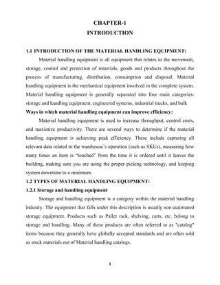
Fig: No: 1.1 A forklift transporting a pallet of potted plants
Forklifts are rated for loads at a specified maximum weight and a specified
forward center of gravity. This information is located on a nameplate provided by
the manufacturer, and loads must not exceed these specifications. In many
jurisdictions it is illegal to remove or tamper with the nameplate without the
permission of the forklift manufacturer.
An important aspect of forklift operation is that most have rear-wheel
steering. While this increases maneuverability in tight cornering situations, it
differs from a driver‟s traditional experience with other wheeled vehicles. While
steering, as there is no caster action, it is unnecessary to apply steering force to
maintain a constant rate of turn.
Another critical characteristic of the forklift is its instability. The forklift and
load must be considered a unit with a continually varying center of gravity with
every movement of the load. A forklift must never negotiate a turn at speed with a
raised load, where centrifugal and gravitational forces may combine to cause a
disastrous tip-over accident.
The forklift are designed with a load limit for the forks which is decreased
with fork elevation and undercutting of the load (i.e. load does not butt against the
fork "L"). A loading plate for loading reference is usually located on the forklift. A
4. 4
forklift should not be used as a personnel lift without the fitting of specific safety
equipment, such as a "cherry picker" or "cage".
Forklift use in warehouse and distribution center .Forklifts is a critical
element of warehouses and distribution centers. It‟s imperative that these structures
be designed to accommodate their efficient and safe movement.
In the case of Drive-In/Drive-Thru Racking, a forklift needs to travel inside
a storage bay that is multiple pallet positions deep to place or retrieve a pallet.
Oftentimes, forklift drivers are guided into the bay through guide rails on the floor
and the pallet is placed on cantilevered arms or rails. These maneuvers require
well-trained operators. Since every pallet requires the truck to enter the storage
structure, damage is more common than with other types of storage. In designing a
drive-in system, dimensions of the fork truck, including overall width and mast
width, must be carefully considered.
5. 5
CHAPTER-2
FLUID POWER
Fluid power technology is a means to convert, transmit, convert and apply
fluid energy to perform useful work. Since a fluid can be either a liquid or a gas,
fluid power in general includes and pneumatics and hydraulics. Oil hydraulics
employs pressurized liquid and pneumatics employs compressed air.
2.1GENERAL APPLICATION OF FLUID POWER:
Agriculture : Farm equipment
Construction : Earth moving equipment, concrete mixing equipment
Ships : Controllable pitch propellers
Aviation : Hydraulic retractable landing wheels
Defense : Missile launches system
Transportation : Hydraulic elevators
Fabrication : Hydraulic presses for metal forming pneumatic hand
tools, Injection molding machine Fabrication
Material handling : Hydraulic jacks‟ hydraulic ram, conveyor system,
pneumatically operated packing warping and bottling
equipments
Automation : Hydraulically operated machine tools, robots‟,
pneumatically Operated indexing holding gripping and
feeding devices.
6. 6
CHAPTER-3
BASIC PRINCIPLES & INTRODUCTION OF HYDRAULICS
AND PNEUMATICS
Pneumatic cylinders are the devices for converting the air pressure into
linear mechanical force and motion. They are basically used for single purpose
applications such as clamping, tilting, bending, turning and many other
applications.
The Pneumatic power is converted to straight line reciprocating motion by
pneumatic cylinders. The various industrial applications for which air cylinders are
used can be divided duty wise into the groups. They are light duty, medium duty
and heavy duty but according to the operating principle air cylinders can be sub
divided as 1.single-acting, 2.Double- acting cylinders. Since our project is based on
single acting cylinder we shall see deep about it.
In a single-acting cylinder, compressed air is fed only in one side hence, this
cylinder can produce work only in one direction the return movement of the piston
is affected by a built–in spring or by application of an external force the spring is
designed to return the piston to its initial position with a sufficiently high speed.
Most industrial processes require substances to be transformed from one
place to another. Also the final products should be shaped (or) compressed (or)
held by applying a great force. Such activities are performed by using prime
movers.
The prime movers are operated by,
(i) Electrical System
(ii) Hydraulic System
(iii) Pneumatic System
7. 7
In electrical system, the rotary motion is provided by simple motors. The
linear motions can be obtained by converting rotary motions with the aid of screw
jack (or) Rack and pinion.
In Hydraulic system, enclosed water (or) oil can be used to convey energy
from one location to another. In Greek, hydra means water.
In Pneumatic system, enclosed gas (normally compressed air) is used to
transfer energy from one location to another). In Greek, Pneumatic means wind.
3.1 HYDRAULIC BASIC PRINCIPLES:
3.1.1 Hydraulic Principles:
There are certain governing principles in a hydraulic system:
1. All liquids are non-compressible and can be used to transmit power.
2. Any load to be lifted offers resistance to flow of liquid. This
resistance to flow is pressure.
3. If the capacity of the pump is more, then it pumps out more liquid. If
it pumps out more liquid, then it makes the hydraulic actuators
(hydraulic cylinder (or) hydraulic for the speed of the hydraulic
actuator.
4. If the force developed in the hydraulic cylinder is more than the
external load, then the actuator lifts the external load. If the force
developed in the hydraulic cylinder is less than the external load, then
the actuator will not lift the external load. The flow rate is nothing to
do with the load carrying capacity of the hydraulic system.
5. If the operation of a hydraulic system, the liquid chooses the path of
least resistance
For example, there are two passages of flow from the pump. One path is
connected to the hydraulic actuator to lift the load. Another path is connected to the
8. 8
reservoir. The liquid will choose the path of least resistance (reservoir path) and
flows back into the reservoir, without choosing the path that offers higher
resistance i.e. lifting the load. Ultimately, the load remains un lifted in this case.
3.1.2 Pascal’s Law:
Fig: No: 3.1 Pascal’s Law
Pascal‟s law states that “The pressure applied anywhere to a confined liquid
it transmitted equally to every portion of the surface of the containing vessel”.
Refer the following fig. When a force is applied to the liquid by a piston, the liquid
transmits this force equally to all surfaces of the container.
3.2 DESCRIPTION OF THE HYDRAULICS COMPONENTS
A Hydraulic cylinder (also called a linear hydraulic motor) is a mechanical
actuator that is used to give a linear force through a linear stroke. It has many
applications, notably in engineering vehicles.
3.2.1 Operation of Hydraulic Actuator:
Hydraulic Actuators:
Pumps convert mechanical input of motor into pressure energy of fluid.
Hydraulic actuators do just the opposite. They convert the pressure energy of fluid
into mechanical output to perform useful work. Fluid power is transmitted through
either linear (or) rotary motion. Linear motion is obtained by using linear actuators
called hydraulic cylinders Rotary motion is obtained by using rotary actuators
9. 9
called hydraulic motors. Rotary actuators are the hydraulic and pneumatic
equivalent of an electric motor.
3.2.1.1 Linear Actuators: (Hydraulic cylinders)
There are two types of hydraulic cylinders.
1. Single acting cylinder
2. Double acting cylinder
Single acting hydraulic cylinder:
The return stroke is actuated by a spring (or) gravity. The simplest type of
linear actuator is the single acting hydraulic cylinder. In this device, the
pressurized liquid is admitted through only one side. So this cylinder will produce
work in only one direction.
Fig: No: 3.2 Single-acting Hydraulic Cylinder
It consists of a piston inside a cylinder body called a barrel. The prison rod is
attached to the one end of the piston. The piston rod extends out during extension
and goes inside cylinder during retraction.
Inlet port is provided at the other end of the cylinder. Single acting cylinders‟
pistons do not retract hydraulically but it is accomplished by using gravity force
(or) using compression spring as shown in the following fig.
The following are the important components of single acting cylinder:
10. 10
1. Cylinder body (or) barrel
2. Two end cover plates
3. Piston
4. Piston rod
5. U-cup seal
6. 0-ring
7. Bush to guide the piston
Fig: No: 3.3 Various Parts of the Single-acting Hydraulic Cylinder
The various parts of single acting cylinder is shown in fig. The end covers
are fitted to the body by using four cover screws (or) tie rods which are not shown
in fig.
Double Acting Hydraulic Cylinder:
In these double acting cylinders, the pressurized liquid is admitted in both
sides of the piston alternately. Work is performed during forward motion as well as
backward motion of the piston. To prevent leakage, seals are provided in five
locations are the important components of double acting cylinder.
1. Two end cover plates (or) two end caps with port connections
(i) Base Cap
(ii) Bearing cap
11. 11
2. Cylinder barrel
3. Piston
4. Piston rod
The end caps are made up of cast iron (or) aluminum and have inlet and
outlet ports. These caps entries are threaded so that it can be locked (or) opened.
End caps should be designed to withstand the impact loads, due to the fluid
pressure and kinetic energy of moving parts.
These shock loads are developed at the extreme ends of piston travels. These
stock loads at the end of travel can be minimized by cushion valves built into the
end caps. This is known as cylinder cushioning.
Fig: No: 3.4 Double-acting Hydraulic Cylinder
Hydraulic cylinders get their power from pressurized hydraulic fluid, which
is typically oil. The hydraulic cylinder consists of a cylinder barrel, in which a
piston connected to a piston rod moves back and forth. The barrel is closed on each
end by the cylinder bottom (also called the cap end) and by the cylinder head
12. 12
where the piston rod comes out of the cylinder. The piston has sliding rings and
seals.
The piston divides the inside of the cylinder in two chambers, the bottom
chamber (cap end) and the piston rod side chamber (rod end). The hydraulic
pressure acts on the piston to do linear work and motion. Flanges, trunnions, and/or
clevises are mounted to the cylinder body. The piston rod also has mounting
attachments to connect the cylinder to the object or machine component that it is
pushing.
A hydraulic cylinder is the actuator or "motor" side of this system. The
"generator" side of the hydraulic system is the hydraulic pump which brings in a
fixed or regulated flow of oil to the bottom side of the hydraulic cylinder, to move
the piston rod upwards. The piston pushes the oil in the other chamber back to the
reservoir. If we assume that the oil pressure in the piston rod chamber is
approximately zero, the force on the piston rod equals the pressure in the cylinder
times the piston area (F=PA).
The piston moves instead downwards if oil is pumped into the piston rod
side chamber and the oil from the piston area flows back to the reservoir without
pressure. The pressure in the piston rod area chamber is (Pull Force) / (piston area -
piston rod area).
Fig: No: 3.5 Cut Section Of The Hydraulic Actuator
13. 13
3.2.1.2 Parts of Hydraulic Actuator:
A hydraulic cylinder consists of the following parts:
Cylinder barrel:
The cylinder barrel is mostly a seamless thick walled forged pipe that must
be machined internally. The cylinder barrel is ground and/or honed internally.
Cylinder Bottom or Cap:
In most hydraulic cylinders, the barrel and the bottom portion are welded
together. This can damage the inside of the barrel if done poorly. Therefore some
cylinder designs have a screwed or flanged connection from the cylinder end cap to
the barrel. (See "Tie Rod Cylinders" below) In this type the barrel can be
disassembled and repaired in future.
Cylinder Head:
The cylinder head is sometimes connected to the barrel with a sort of a
simple lock (for simple cylinders). In general however the connection is screwed or
flanged. Flange connections are the best, but also the most expensive. A flange has
to be welded to the pipe before machining. The advantage is that the connection is
bolted and always simple to remove. For larger cylinder sizes, the disconnection of
a screw with a diameter of 300 to 600 mm is a huge problem as well as the
alignment during mounting.
Piston:
The piston is a short, cylinder-shaped metal component that separates the
two sides of the cylinder barrel internally. The piston is usually machined with
grooves to fit elastomeric or metal seals. These seals are often O-rings, U-cups or
cast iron rings. They prevent the pressurized hydraulic oil from passing by the
piston to the chamber on the opposite side. This difference in pressure between the
two sides of the piston causes the cylinder to extend and retract. Piston seals vary
14. 14
in design and material according to the pressure and temperature requirements that
the cylinder will see in service. Generally speaking, elastomeric seals made from
nitride rubber or other materials are best in lower temperature environments while
seals made of Viton are better for higher temperatures. The best seals for high
temperature are cast iron piston rings.
Piston Rod:
The piston rod is typically a hard chrome-plated piece of cold-rolled steel
which attaches to the piston and extends from the cylinder through the rod-end
head. In double rod-end cylinders, the actuator has a rod extending from both sides
of the piston and out both ends of the barrel. The piston rod connects the hydraulic
actuator to the machine component doing the work.
This connection can be in the form of a machine thread or a mounting
attachment such as a rod-clevis or rod-eye. These mounting attachments can be
threaded or welded to the piston rod or, in some cases; they are a machined part of
the rod-end.
Rod Gland:
The cylinder head is fitted with seals to prevent the pressurized oil from
leaking past the interface between the rod and the head. This area is called the rod
gland. It often has another seal called a rod wiper which prevents contaminants
from entering the cylinder when the extended rod retracts back into the cylinder.
The rod gland also has a rod bearing. This bearing supports the weight of the
piston rod and guides it as it passes back and forth through the rod gland. In some
cases, especially in small hydraulic cylinders, the rod gland and the rod bearing are
made from a single integral machined part.
Other parts
Cylinder bottom connection
Seals
15. 15
Cushions
A hydraulic cylinder should be used for pushing and pulling only. No
bending moments or side loads should be transmitted to the piston rod or the
cylinder. For this reason, the ideal connection of a hydraulic cylinder is a single
clevis with a spherical ball bearing. This allows the hydraulic actuator to move and
allow for any misalignment between the actuator and the load it is pushing.
3.3 SPECIAL HYDRAULIC CYLINDER:
3.3.1 Telescopic Cylinder:
The length of a hydraulic cylinder is the total of the stroke, the thickness of
the piston, the thickness of bottom and head and the length of the connections.
Often this length does not fit in the machine. In that case the piston rod is also used
as a piston barrel and a second piston rod is used. These kinds of cylinders are
called telescopic cylinders.
If we call a normal rod cylinder single stage, telescopic cylinders are multi-
stage units of two, three, four, five and even six stages. In general telescopic
cylinders are much more expensive than normal cylinders. Most telescopic
cylinders are single acting (push). Double acting telescopic cylinders must be
specially designed and manufactured.
3.3.2 Plunger Cylinder:
A hydraulic cylinder without a piston or with a piston without seals is called
a plunger cylinder. A plunger cylinder can only be used as a pushing cylinder; the
maximum force is piston rod area multiplied by pressure. This means that a piston
cylinder in general has a relatively thick piston rod.
3.3.3 Differential Cylinder:
16. 16
A differential cylinder acts like a normal cylinder when pulling. If the
cylinder however has to push, the oil from the piston rod side of the cylinder is not
returned to the reservoir, but goes to the bottom side of the cylinder. In such a way,
the cylinder goes much faster, but the maximum force the cylinder can give is like
a plunger cylinder. A differential cylinder can be manufactured like a normal
cylinder, and only a special control is added.
17. 17
CHAPTER-4
4. HYDRAULIC PUMP
4.1 CHARACTERSTICS OF THE HYDRAULIC PUMP
Hydraulic pumps are used to pump out the liquid from the reservoir to the
hydraulic actuator through a set of valves.
A pump converts mechanical energy into hydraulic energy. The mechanical
energy is given to the pump by an electric motor. Due to mechanical action, the
pump creates a partial vacuum at its inlet.
This makes the atmospheric pressure to force the liquid through the inlet line
and into the pump. The pump then pushes the liquid into the hydraulic system.
The pumps are classified as:
(i) Positive displacement pumps
(ii) Hydrodynamic (or) Non-positive displacement pumps
Hydrodynamic (or) Non-positive displacement pumps are used for
transporting fluids from one location to another. These types of pumps are
generally used for low pressure, high-volume flow applications, since they are not
capable of withstanding high pressures.
The centrifugal pumps and axial flow pumps are the examples of non-
positive displacement pumps. These pumps provide smooth flow. But the output
flow rate is reduced when the resistance to flow is increased.
Positive displacement pumps have the internal working elements which
make a very close fit together so that there is very little leakage (or) slippage
between them. This type of pumps ejects a fixed quantity of liquid into the
hydraulic system per revolution of the pump shaft.
18. 18
4.2 ADVANTAGES:
These pumps have the following advantages:
High pressure capability
Small and compact size
High volumetric efficiency
Great flexibility of performance, i.e. these pumps can operate
over a wide range of pressure requirements and speed ranges.
4.3 HYDRAULIC PUMP TYPES:
Gear pumps
Gear rotor pumps
Rotary vane pumps
Screw pumps
Bent axis pumps
Axial piston pumps swash plate principle
Radial piston pumps
Peristaltic pumps
Multi pump assembly
4.4 PUMP SELECTION:
Pumps are selected by considering the following factors:
1. Discharge (flow rate) requirements. (in liters/mm)
2. Operating speed (in rpm)
3. Pressure rating (in bar)
4. Performance
5. Reliability
6. Maintenance
7. Cost
8. Noise
19. 19
4.5 HYDRAULIC PUMP WORKING PRINCIPLES:
4.5.1 Gear Pumps:
Fig: No: 4.1 Gear Pump
Gear pumps (with external teeth) (fixed displacement) are simple and
economical pumps. The swept volume or displacement of gear pumps for
hydraulics will be between about 1 cm3 (0.001 liter) and 200 cm3 (0.2 liter). These
pumps create pressure through the meshing of the gear teeth, which forces fluid
around the gears to pressurize the outlet side. Some gear pumps can be quite noisy,
compared to other types, but modern gear pumps are highly reliable and much
quieter than older models.
4.5.2 Gear Rotor Pumps:
Fig: No: 4.2 Gear Rotor Pump
20. 20
Gear rotor pumps (fixed displacement) are a variation of gear pumps, having
internal teeth of optimized design. The efficiency and noise level are very good for
such a medium pressure pump.
4.5.3 Rotary Vane Pumps:
Rotary vane pumps (fixed and simple adjustable displacement) have higher
efficiencies than gear pumps, but are also used for mid pressures up to 180 bars in
general. Some types of vane pumps can change the centre of the vane body, so that
a simple adjustable pump is obtained. These adjustable vane pumps are in general
constant pressure or constant power pumps: the displacement is increased until the
required pressure or power is reached and subsequently the displacement or swept
volume is decreased until equilibrium is reached.
4.5.4 Screw Pumps:
Screw pumps (fixed displacement) are a double Archimedes spiral, but
closed. This means that two screws are used in one body. The pumps are used for
high flows and relatively low pressure (max 100 bars). They were used on board
ships where the constant pressure hydraulic system was going through the whole
ship, especially for the control of ball valves, but also for the steering gear and help
drive systems. The advantage of the screw pumps is the low sound level of these
pumps; the efficiency is not that high.
4.5.5 Bent Axis Pumps:
Bent axis pumps, axial piston pumps and motors using the bent axis
principle, fixed or adjustable displacement exists in two different basic designs.
The Thoma-principle (engineer Hans Thoma, Germany, patent 1935) with max 25
degrees angle and the Wahl mark-principle (Gunnar Axel Wahl mark, patent 1960)
with spherical shaped pistons in one piece with the piston rod, piston rings, and
maximum 40 degrees between the driveshaft centerline and pistons (Volvo
Hydraulics Co.). These have the best efficiency of all pumps. Although in general
21. 21
the largest displacements are approximately one liter per revolution, if necessary a
two liter swept volume pump can be built. Often variable displacement pumps are
used, so that the oil flow can be adjusted carefully. These pumps can in general
work with a working pressure of up to 350-420 bars in continuous work.
Axial Piston Pumps Swash Plate Principle:
Axial piston pumps using the swash plate principle (fixed and adjustable
displacement) have a quality that is almost the same as the bent axis model. They
have the advantage of being more compact in design. The pumps are easier and
more economical to manufacture; the disadvantage is that they are more sensitive
to oil contamination.
4.5.6 Radial Piston Pumps:
Radial piston pumps (fixed displacement) are used especially for high pressure and
relatively small flows. Pressures of up to 650 bar are normal. In fact variable
displacement is not possible, but sometimes the pump is designed in such a way
that the plungers can be switched off one by one, so that a sort of variable
displacement pump is obtained.
4.5.7 Peristaltic Pumps:
Peristaltic pumps are not generally used for high pressures. Pumps for open
and closed systems
4.6 MULTI PUMP ASSEMBLY:
In a hydraulic installation, one pump can serve more cylinders and motors.
The problem however is that in that case a constant pressure system is required and
the system always needs the full power. It is more economic to give each cylinder
and motor its own pump. In that case multi pump assemblies can be used. Gear
pumps can often be obtained as multi pumps. The different chambers (sometimes
of different size) are mounted in one body or built together. Also vane pumps can
22. 22
often be obtained as a multi pump. Gear rotor pumps are often supplied as multi
pumps. Screw pumps can be built together with a gear pump or a vane pump. Axial
piston swash plate pumps can be built together with a second pump of the same or
smaller size, or can be built together with one or more gear pumps or vane pumps
(depending on the supplier). Axial plunger pumps of the bent axis design cannot be
built together with other pumps.
4.7 HYDRAULIC HOSE:
The hose is long cylindrical tube designed to carry power in the form of
fluids from one place to other. Hoses are generally made up of polyethylene, PVC,
or synthetic or natural rubber with a combination of metal wires to give strength.
Common parameters are diameter, wall thickness and pressure rating.
Fig: No: 4.3 Hydraulic Hose
23. 23
CHAPTER-5
HYDRAULIC FLUIDS
5.1 SPECIFICATIONS:
Some of the specifications of the fluids are not given mainly the kinematic
viscosities of the fluids at 40°C and 100°C which are used to calculate viscosity
index of the fluid. The kinematic viscosities of the fluids at both temperatures has
been measured in flumes lab by using Ubbelohde viscometer where it is used in
most of the test methods like ISO 3104, ISO 3105, ASTM D 445, ASTM D 446,
BS 188, IP 71.
To calculate viscosity index of the petroleum products, lubricants or other
types of hydraulic fluid according to „ISO 2909:2002‟ or „ASTM D2270 - 10e1‟
standards it requires kinematic viscosities [cSt] at two different temperature. One is
at 40°C and other is at 100°C. But these two standards are used to calculate the
viscosity index of the fluids from 2 cSt to 70 cSt at 100°C. The viscosity index of
the fluids has calculated by using online calculator [3]. The difference in
viscosities between the given data and the measured is due to error in the
viscometer. But this does not affect in estimating the viscosity of the fluid with
respect to temperature.
HYDRAULIC FLUID:
Hydraulic fluid is a medium to transfer power in the system or the
machinery. Hydraulic fluids play a very important role in the developing world.
The fluids are classified on the basis of their viscosity, which makes a chart which
is useful for the industries to select the fluid for the particular function. The
classifications range from a simple ISO (International Organization for
Standardization) to the recent classification ASTM D 6080-97 (classifying based
on viscosity).
24. 24
5.2 CLASSIFICATION OF HYDRAULIC FLUIDS BASED ON ISO
VISCOSITY GRADE:
Most of the fluids used are classified with ISO standards. The ISO standard
fluids are mainly classified based on the kinematic viscosity at 400C. The fluid is
mainly taken at 400C which is taken as a reference temperature between the
maximum operating and the ambient temperatures. The ISO classification is done
on 18 main fluids based on their viscosity grade. Table.2.1 shows the viscosity
range of a fluid on its ISO VG.
Classification of hydraulic fluids based on ISO Viscosity grade:
ISO VISCOSITY GRADS BASED ON KINEMATIC VISCOSITY
[CENTISTOKES/CST] AT 400C
ISO VG Minimum [cSt] Maximum[cSt]
2 1.98 2.42
3 2.88 3.52
5 4.14 5.06
7 6.12 7.48
10 9.0 11
15 13.5 16.5
22 19.8 24.2
32 28.8 35.2
46 41.4 50.6
68 61.2 74.8
100 90 110
150 135 165
220 198 242
320 288 353
460 4147 506
25. 25
680 612 748
1000 900 1100
1500 1350 1650
Table: No: 5.1 ISO Viscosity Grads Based On Kinematic Viscosity
5.3 TYPES OF HYDRAULIC FLUIDS:
According to ISO there are three different types of fluids according to their
source of availability and purpose of use.
5.3.1 Mineral-Oil based Hydraulic fluids:
As these have a mineral oil base, so they are named as Mineral-oil-Based
Hydraulic fluids. This kind of fluids will have high performance at lower cost.
These mineral oils are further classified as HH, HL and HM fluids. Type HH
fluids are refined mineral oil fluids which do not have any additives. These fluids
are able to transfer power but have less properties of lubrication and unable to
withstand high temperature.
These types of fluid have a limited usage in industries. Some of the uses are
manually used jacks and pumps, low pressure hydraulic system etc. Type HL
fluids are refined mineral oils which contain oxidants and rust inhibitors which
help the system to be protected from chemical attack and water contamination.
These fluids are mainly used in piston pump applications.
HM is a version of HL-type fluids which have improved anti-wear additives.
These fluids use phosphorus, zinc and sulphur components to get their anti-wear
properties. These are the fluids mainly used in the high pressure hydraulic system.
26. 26
Fire Resistant Fluids
These fluids generate less heat when burnt than those of mineral oil based
fluids. As the name suggests these fluids are mainly used in industries where there
are chances of fire hazards, such as foundries, military, die-casting and basic metal
industry.
These fluids are made of lower BTU (British thermal unit) compared to
those of mineral oil based fluids, such as water-glycol, phosphate ester and polyol
esters. ISO have classified these fluids as HFAE (soluble oils), HFAS (high water-
based fluids), HFB (invert emulsions), HFC (water glycols), HFDR (phosphate
ester) and HRDU (polyol esters).
Environmental Acceptable Hydraulic Fluids (EAHF):
These fluids are basically used in the application where there is a risk of
leakage or spills into the environment, which may cause some damage to the
environment. These fluids are not harmful to the aquatic creatures and they are
biodegradable.
These fluids are used in forestry, lawn equipment, off-shore drilling, dams
and maritime industries. The ISO have classified these fluids as HETG (based on
natural vegetable oils), HEES (based on synthetic esters), HEPG (polyglycol
fluids) and HEPR (polyalphaolefin types).
27. 27
5.4 CLASSIFICATION OF HYDRAULIC FLUIDS:
Fig: No: 5.1 Classifications Of Hydraulic Fluids
5.5 FLUID PROPERTIES AND COMPARATIVE PERFORMANCES:
While selecting a hydraulic fluid one has to be aware of hydraulic fluid
properties and its effect on hydraulic system. Generally the hydraulic fluids have
many properties and some of the important properties are explained in detail
below.
Density (ρ):
Density is expressed as mass occupied in a unit volume. The density is
inversely proportional to temperature. The SI unit of density is kg/m3
Viscosity:
The most important property of the hydraulic fluid to be considered is
viscosity of the fluid. The main selection of fluid for the system depends on the
viscosity of fluid. Viscosity is the measure of resistance of fluid flow that is inverse
28. 28
measure of fluidity. For example honey is very thick that means it is more viscous
than water. Viscosity is directly related to system (especially pump and motor)
wear, leakage, and most important efficiency.
5.6 STANDARD TEST METHODS:
For hydraulic fluids:
It is important to know the specification of the fluid while selecting the fluid
for the hydraulic system. Here are some of the important specification and their
standard test methods in brief.
5.6.1 Viscosity:
This test determines the kinematic viscosity of the hydraulic fluids and
liquid petroleum products both opaque and transparent. There are different
standards like ISO 3104, ISO 3105, ASTM D445, ASTM D446, IP 71, DIN 51366,
BS 188 to measure kinematic viscosity. All these standards uses nearly same
method to test kinematic viscosity. For this test method glass capillary viscometer
is used to determine the kinematic viscosity. In this the time is calculated for the
fluid to fall under its own gravity from one point to another at constant temperature
and then it is multiplied by viscometer constant to get kinematic viscosity in
centistokes. The viscosity is measured minimum at two different temperatures
mostly at 40°C and 100°C, so that viscosity index of the fluid can be calculated.
5.6.2 Total acid number (TAN):
Total acid number is the presence of milligrams of potassium hydroxide
(KOH) per gram of sample. This TAN indicates the potential of corrosion
problems. ISO 6618, ASTM D664 and ASTM D974 are some of the standard
methods. In ISO 6618 „color indicating titration‟ method is used to measure the
acid number where an appropriate pH color indicator is added to the sample. The
29. 29
volume of color titrant that is added to change the color of the sample permanently
is used to calculate acid number.
5.6.3 Flash Point:
Flash point is the minimum temperature at which the fluid vaporize to form
ignitable mixture in air when fire is brought over this mixture. The standard
methods are ISO 2592, ASTM D92. In these two standards „Cleveland open cup
method‟ is used to determine flash point. For this the Cleveland apparatus is filled
with fluid and then its temperature is increased rapidly at first and then slowly till it
reaches its theoretical flash point. Then a small fire is brought over the apparatus,
therefore the minimum temperature at which the mixture ignites is considered as
flash point.
5.6.4 Pour Point:
The pour point is the minimum temperature at which the fluid becomes
semi-solid and loses its fluidity. There are different test standards for different
types of fluid, for example ISO 3016 for the petroleum products. Other standards
are ASTM D97, ASTM D 2500 etc. The general procedure for petroleum products
is the fluid is cooled to form paraffin crystals. Then the temperature is maintained
at above 9°C above the expected pour point. For every subsequent 3°C temperature
the apparatus is tilted to check the surface. If there is no movement in fluid then the
apparatus is kept horizontal for 5 seconds. If the fluid does not flow then it is
considered as pour point.
5.6.5 Water content:
This test is used to determine the water content in the fluid. Water in fluid is
the main problem that decreases viscosity and forms rust. So the user has to check
whether the fluid is suitable for the machine with that water content. Some of the
standard tests are ISO 12937 and ISO 6296 which uses „Karl Fischer titration
method‟ to find water content.
30. 30
5.6.6 Air Release:
Air release property is important parameter to be considered mainly in the
systems where residue time is short because the air flows with fluid causes
pressure losses in the system. Some of the standard test methods are ISO 9120,
ASTM D3472, IP 313 and DIN 51381 where air is blown into the fluid and the
time taken by the air to decrease it‟s volume by 0.2 % at constant temperature is
considered as air release time.
5.6.7 Low Temperature Fluidity:
This test determines the highest possible viscosity of fluid at very low
temperature for a certain period of time. This is useful for the system when it is
stand still for long time at low temperature. The standard test method is ASTM
D2532.
Elements by ICP:
This test is used to determine the additive elements in the fluid. This test
provides wear indication of the hydraulic machines by testing used oil.
„Inductively Coupled Plasma (ICP) Atomic Emission Spectrometry‟ is used t
determine the elements and it can measure the elements down to 0.1 parts per
million. ASTM D5185 and ASTM D4951 are the standard tests.
5.6.8 Oxidation Stability:
This test is used to determine the oxidation stability of the fluid. The
standard tests are ASTM D943 and DIN 51554-3. In DIN 51554-3. 70 ml of oil is
kept at 95°C for 35 days in atmospheric oxygen and it is stirred with glass stirrer
connected to copper strip at a speed of 24 stirs per minute. Then the viscosity, acid
number and other parameters are measured for every week.
5.6.9 Hydrolytic stability:
There are more chances of fluid to get contaminated with water which
decreases viscosity, forms rust that decrease the performance of the system. So it is
31. 31
important to know the hydrolytic stability of the fluid. The ASTM D2619 is the
standard test method where 75 g of fluid, 25 grams of water and a copper strip is
sealed in vessel and stirred at 5 rpm for 48 hrs at 93°C. Then the acid number and
viscosity is measured to find the hydrolytic stability.
5.6.10 Thermal Stability:
The effect of temperature on the metals is also an important factor. The
ASTM D2070 is the standard test method in which copper and steel rods are
placed in the oil at a temperature of 135°C for one week. Then the condition of the
metal specimens is noticed and viscosity of fluid is also measured.
For fluid power components:
Pump is the core component for the fluid power system. So it is important to
know the performance of the pump at different working conditions. To know the
performance volumetric and mechanical efficiency of the pump should be
measured.
To test the pump
1. Inlet pressure of the pump should be kept constant. Record the
measurements of
2. Input torque
3. Outlet flow of the pump.
4. Fluid temperature.
5. Drainage flow (if needed) Now test the pump
a) At constant speed and by varying the outlet pressure of
the pump.
b) By varying the speed of the pump at constant pump
outlet pressure.
By using these two tests calculate the efficiencies of the pump by the
following equations
33. 33
CHAPTER-6
HYDRAULIC VALVE
6.1 Hydraulic Valves Pressure Flow Direction Controls Applications:
Fluid power is controlled primarily through the use of control devices called
valves. Hydraulic and pneumatic systems require control valves to direct and
regulate the flow of fluid from pump (or compressor to hydraulic cylinders (or)
hydraulic motors.
The selection of these control devices depends on the type, size, actuating
technique and remote control capability. There are three basic types of control
valves.
(i) Direction control valves
(ii) Pressure control valves
(iii) Flow control valves
Direction control valves are used to determine the path of the fluid through
which it should travel within a given circuit.
The control of fluid path is carried out by check valves, shuttle valves and two
ways, three way and four way direction control valves.
Pressure control valves are used to protect the hydraulic system against over
pressure. This over pressure may occur due to a gradual buildup as fluid demand
decreases (or) due to sudden surge as valve close.
The buildup of pressure is controlled by pressure relief, pressure reducing,
sequence, unloading and counter balance valves.
The fluid flow must be controlled in hydraulic circuits. The control of
actuator speeds depends on the flow rates. So to control the actuator speed, the
flow rate should be controlled by using flow control valves.
There are some practical differences between the hydraulic and pneumatic
direction control valves, even though the principle of operation is the same. But the
34. 34
pressure and the flow control valves for both hydraulic and pneumatic systems are
same.
6.2 DIRECTION CONTROL VALVES:
As the name implies, the direction control valves are used to control the
direction of the flow to the actuator from the pump.
The following are the important types of direction control valves in the hydraulic
system.
1. Check Valve
2. Two position two way valves
3. Two position four way valves
4. Three position four way valves
5. Rotary four way valve
6. Shuttle valve
6.2.1 Check Valve:
The simplest type of one direction flow valve is check valve. Check valve is
a one way valve because it permits flow in only one direction and prevents any
flow in the opposite direction. The check valve with graphical symbol is shown in
figure.
Fig: No: 6.1 Check Valve
35. 35
The spring holds the poppet in the closed position. When the fluid attains the
required pressure, it overcomes the spring force, the spring is compressed the
poppet is moving right and free flow occurs from left to right.
If the flow is attempted in the opposite direction, the fluid pressure along
with the spring force pushes the poppet in closed position. Hence, no flow is
occurred in opposite direction. The graphic symbol shows the function of the check
valve.
Fig: No: 6.2 Pilot Operated Check Valve
Another type of check valve is the pilot operated check valve. It is shown in
fig with its symbol. The pilot operated check valve always permits free flow in
one direction but permits flow in the normally blocked opposite direction only if
pilot pressure punches the pilot piston downward. Irk this construction, the pilot
piston is attached (or) integral part of the valve poppet.
The spring holds the poppet seated in a no flow condition by pushing against
the piston.
In the symbol, the dashed line represents the pilot pressure line connected to
the pilot pressure port of the valve. The pilot operated check valves are frequently
used to lock the hydraulic cylinders in position.
36. 36
6.2.2 Rotary Four way valves:
Spool designs are mostly used like rotary four way valve. It has shown in
figure the corresponding for direction control valves. However, other types are
consists of a rotor closely fitted inside a valve body graphic symbol is also shown
here.
Fig: No: 6.3 Rotary Four-way Valve
When the rotor is rotating inside the valve body, it connects (or) closes the
passages with the ports A (or) B (or) P (or) T, to provide four flow paths. The
figure shows the three position valve.
1. In the first position, the pressure port P is connected to the port A and
the port B is connected to the tank T.
2. In the 2nd position centered position, all four ports are blocked.
3. In the third position, the pressure port P is connected to port B and the
port A is connected to tank T. Rotary valves are usually operated by
manually (or) mechanically.
37. 37
6.2.3 Shuttle Valve:
Shuttle valve is another type of direction control valve. It allows a system to
operate from either of two fluid power sources. It is also known as a double check
valve. It is mostly used in pneumatic device and is rarely used in hydraulic circuits.
Similarly, when the pressure is applied through port Y, the ball is blown to
the left blocking the port X, and the ports Y and A are connected. The construction
and symbol are shown here.
Fig: No: 6.4 Shuttle Valve
Since the ball is shuttled to one side (or) the other side of the valve
depending on which side of the ball has the greater pressure, it is known as shuttle
valve. This shuttle valve is used for safety purpose in the event that the main pump
can no longer provide hydraulic power to operate emergency devices; the shuttle
valve will shift to allow fluid to flow from a secondary backup pump.
6.2.4 Pressure Control Valves:
The pressure control valves are used in hydraulic circuits to maintain desired
pressure in various parts of the circuits.
The most widely used type of pressure control
38. 38
Fig: No: 6.5 Pressure Control Valve- Relief Valve
It is also employed as a backup device when the main pressure control
device fails. The simple relief valve is shown in figure. A poppet is held seated
inside the valve by a heavy spring. When the system pressure reaches enough high
pressure, the poppet is forced off its seat.
This allows the flow through the outlet to tank as long as the high pressure
level is maintained. The adjusting screw cap is used to vary the spring force and
thus to vary the cracking pressure at which the valve begins to open.
Fig: No: 6.6 Symbolic Representation of Partial Hydraulic Circuit
39. 39
The symbol for simple relief valve is shown here. A partial hydraulic circuit
consisting of pump and pressure relief valve is shown symbolically.
If the hydraulic system obtain maximum pressure (cracking pressure), then all the
pump flow will return back to the tank through the relief valve.
The pressure relief valve protects the hydraulic system against any overloads. If a
pressure compensated vane pump is used, then pressure relief valve is not needed.
The main function of a pressure relief valve is to control the force or torque
produced by hydraulic actuators.
40. 40
CHAPTER-7
CONSTRUCTION AND LINE DIAGRAM OF HYDRAULIC
FORK LIFT
cylinder and piston Assly
pump
wheels
structure
arm
fork lift
Fig: No: 7.1 Hydraulic fork lift
41. 41
CHAPTER-8
WORKING PRINCIPLE
Here in our project fork lift machine is done by hydraulic system. It consists
of structure, arm, cylinder and piston assembly, with wheels and hydraulic circuit.
In this project of the fabricated model of hydraulic fork lift for industries
will describe the working principles as well as hydraulic machines application and
its advantages. Efforts have been taken to show the path of hydraulic fluid as it is
applied and released.
The Hydraulic system pressure can be generated in the form of any physical
action which result a compression over the Hydraulic system or pneumatic
pressure which is developed in the form of air compressing externally can be
applied to activate Hydraulic system. After fork lift loaded when pump is pumped
the hydraulic cylinder will moves upward, holds the object and will lift gradually.
The light duty of fork lift move easily with the help of wheel. No extra skill is
required for operating this system and then it is Easier to maintain. Hence the
operation is very smooth and in this system we can get more output by applying
less effort.
42. 42
CHAPTER-9
BILL OF MATERIALS
9.1 MATERIALS USED:
Table: No: 9.1 Bill of materials
NAME OF THE COMPONENTS MATERIALS
Hydraulic pump(linear type pump) Steel
Cylinder M.S rod
Piston M.S with chromium
Ram M.S rod
Spring M.S
Nipple M.S rod
End plate M.S plate
Hydraulic Fluid
Structure M.S.Plate
43. 43
CHAPTER-10
ADVANTAGES AND DISADVANTAGES
10.1 ADVANTAGES:
1. The process uses low- cost energy source.
2. Large machines frames are not required on the process.
3. Intricate shapes on material of low form ability can be worked fairly
easily.
4. It does not require special type hoses.
5. No extra skill is required for operating this system.
6. Easier maintenance.
7. Operation is very smooth and in this system we can get more output
by applying less effort.
8. Simple construction of additional accessories not needed.
9. Comparatively cheaper in cost then the other systems.
10.Quick response is achieved.
11.Continuous operation is possible without stopping.
12.More efficient.
13.Power can be easily transmission.
14.Less loss in transmission.
15.Very Easy Collecting Process.
10.2 DISADVANTAGES:
1. Machining work is very complicated.
2. Very sturdy base needed.
3. Hydraulics components cost is high.
44. 44
CHAPTER-11
11. CONCLUSION
Therefore, the result obtain from the project is to reduces the time taken and
efficiency over the other system. The necessary requirements and fulfillment of the
project details which we have given is factual.
This report details with design of hydraulic fork lift with suitable drawing.
The project carried out by us made an impressing task. The operation is Simple in
construction where as additional accessories are not needed. It is comparatively
cheaper in cost than the other systems. The system becomes as a Quick response
and then Continuous operation is possible without stopping.
Through this type of changes in hydraulics principle and its application we
have increased the performance etc...
45. 45
BIBLOGRAPHY:
1. GUPTA J.K and KHURUMI R.S (1981) “Text book of Machine Design”,
S.Chand & comp and.
2. Parr. ANDREW (2003) „Hydraulic & Pneumatics‟ Butterworth Heimann
Ltd
3. Dr.D.K.AGGARVAL & Dr.P.C SHARMA(2004) “machine design”,
S.K.Kataria and sons
4. MAJUMDAR.S.R “Pneumatic systems”, Tata McGraw-hills company ltd.
5. SRINIVASAN.R(2004) “Hydraulic & pneumatic controls”, Vijay Nicole
imprints private ltd.