Downloaded 55 times
![10. Take-up. Type (mechanical screw or automatic),
location, and total amount of movement (included in
sketch).
11. Width of Belt. (Inches) Include width of pulley face
width, if known.
First, the Effective Belt Tension (TE) must be calculated. TE
is the sum of the tension required to move the empty belt
(TC), the tension required to move the load horizontally (TL),
and the tension required to lift the load (TH).
Example 1. TE = TC + TL + TH
Calculations
TC = F1 x L x CW
F1 = .035" [Normal friction factor for average conditions
(over 20°F) to move empty belt.]
L = Belt length (ft.)
CW = Weight of conveyor belt components. See Table
A.
TL = F2 x L x MW
F2 = .04" [Normal friction factor to move load
horizontally.]
L = Belt length (ft.)
MW = Material weight (lbs. per lineal foot).
MW = 33.3 TPH/Belt Speed (fpm) o rTotal material
load in lbs/L.
TH = H x MW
H = Difference in elevation of terminal pulleys (ft.)
TE = TC + TL + TH
(Continue with calculation of TS and then TO.)
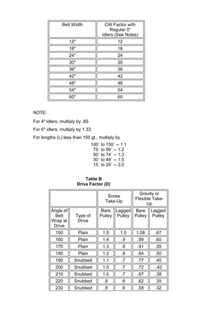
Table A
Weight of Moving Conveyor Components](https://image.slidesharecdn.com/belttensioncalculation-150611093931-lva1-app6891/85/Belt-tension-calculation-2-320.jpg)


This document provides instructions for calculating the proper tension for a conveyor belt based on operating conditions and specifications. It outlines 12 key pieces of information needed, such as carrying surface, drive data, environment, loading rate and pulley diameters. It then describes calculating the effective belt tension as the sum of tensions to move the empty belt, load and lift the load. Additional tension is added to prevent slippage. The proper reinforcement ply is then selected based on flexibility, load support and impact resistance. Motor horsepower requirements and maximum tension the system can generate are also calculated.


