Download to read offline
![8
V
̇ = 3
𝑙 ×
1𝑚3
1000𝑙
𝑚𝑖𝑛×
60𝑠
1𝑚𝑖𝑛
= 5 × 10⁻⁵ 𝑚3
𝑠
, V
̇ = 1.73
𝑙 ×
1𝑚3
1000𝑙
𝑚𝑖𝑛×
60𝑠
1𝑚𝑖𝑛
= 2.8 × 10⁻⁵ 𝑚3
𝑠
∆Tlm =
(T1 − t2) − (T2 − t1)
ln
(T1 − t2)
(T2 − t1)
=
(39.1 − 10.8) − (35.2 − 0.43)
ln
(39.1 − 10.8)
(35.2 − 0.43)
∆Tlm = 31.42 o
C
ρ =
m
v
ṁ = ρ × V
̇ = (For hot water)
ṁ = 993.21 × 5 × 10−5
= 0.04967
kg
s
q = 0.04967 × 4.174[(312.25) − (308.35)] = 0.808 kW = 808 W
q = U×A×∆Tlm
U =
q
A × ∆T𝑙𝑚
=
808
0.02 × 31.42
= 1285.8
w
m2. k](https://image.slidesharecdn.com/htrlab-exp-02a-g-a2-231202135439-bc974fd5/85/HTR-Lab-Exp-02a-G-A2-pdf-10-320.jpg)
![9
6. References
1. Cavallo, C. (2021). All About Double Pipe Heat Exchangers - What You
Need To Know. [online] www.thomasnet.com. Available at:
https://www.thomasnet.com/articles/process-equipment/double-pipe-heat-
exchangers/. [Accessed 30 Sep. 2021].
2. Ghani, S., Gamaledin, S.M.A., Rashwan, M.M. and Atieh, M.A. (2018).
Experimental investigation of double-pipe heat exchangers in air
conditioning applications. Energy and Buildings, [online] 158, pp.801–811.
Available at:
https://www.sciencedirect.com/science/article/pii/S0378778817311866
[Accessed 1 Oct. 2021].](https://image.slidesharecdn.com/htrlab-exp-02a-g-a2-231202135439-bc974fd5/85/HTR-Lab-Exp-02a-G-A2-pdf-11-320.jpg)

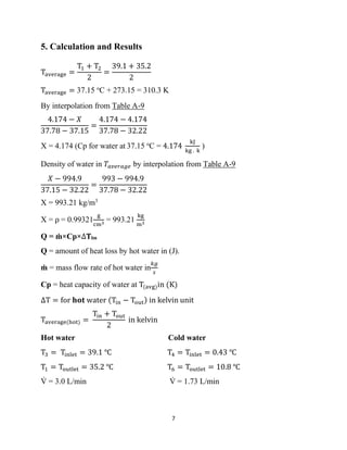
This lab report summarizes an experiment conducted to calculate the overall heat transfer coefficient in a shell and tube heat exchanger with uniflow configuration. Temperature and flow rate data was collected for the hot and cold fluids. The average temperature difference and heat transfer rate were calculated. The overall heat transfer coefficient was determined to be 1285.8 W/m2.K.


