Download to read offline


![2
2. Theory/Introduction
Heat transfer occurs in three main ways: conduction, convection, and
radiation. More than one of these may take place at the same time. Heat is
transferred from warmer objects to colder ones, and not vice versa. It is of great
interest to physical scientists and engineers, for it has applications in varied fields
such as construction and medicine. Engineers and architects study it to design
heating and cooling systems, and physicians use thermometers to measure the
temperature of their patients, for example. [1]
Figure (1) – There are many example for heat transfer
Fourier’s theory of heat conduction: has now almost two centuries,
however it remains a fascinating topic that leads to numerous experiences in
experimental physics. [2]
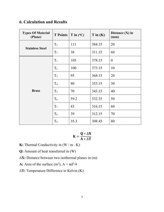
dQ/dt = -k*A*(dT/dx)
Where A is the surface area and k is the thermal conductivity of the material.
What is the effect of average temperature on the values of thermal
conductivity for brass?
The heat flow through a material cannot always be evaluated at steady state
for instance through the wall of a furnace that is being heated or cooled. calculate
the heat flow under these conditions it is necessary to find the temperature
distribution through the solid and how distribution Vanes With time, Using the
equipment set-up described above, it is a simple matter of monitoring the
temperature profile variation during either a heating or cooling cycle thus facilitating
the Study Of unsteady State conduction. [3]](https://image.slidesharecdn.com/htrlab-exp-03-g-a2-231202135526-ac6b94a1/85/HTR-Lab-Exp-03-G-A2-pdf-4-320.jpg)
![9
7. References
1. www.brighthubengineering.com. (2009). What is Thermal Conduction?
Introduction to Heat Transfer: Part One. [online] Available at:
https://www.brighthubengineering.com/hvac/47238-what-is-thermal-
conduction/. [Accessed 12 Apr. 2022].
2. PhysicsOpenLab. (n.d.). Temperature Logging & Heat Conduction. [online]
Available at: https://physicsopenlab.org/2020/04/14/temperature-logging-
heat-conduction/ [Accessed 12 Apr. 2022].
3. Hahn, D.W. (2012). Heat conduction. Hoboken, N.J.: Wiley. [eBook]
Available at:
https://books.google.iq/books?id=C9qwb9Vymy8C&dq=heat+conduction+b
ook&source=gbs_navlinks_s [Accessed 12 Apr. 2022].](https://image.slidesharecdn.com/htrlab-exp-03-g-a2-231202135526-ac6b94a1/85/HTR-Lab-Exp-03-G-A2-pdf-11-320.jpg)

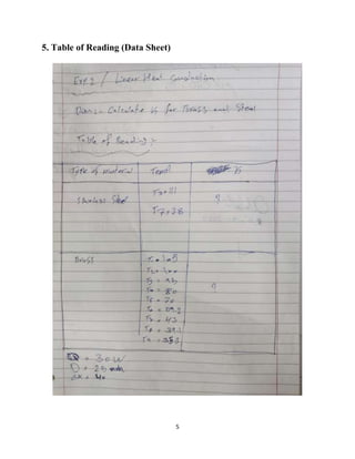
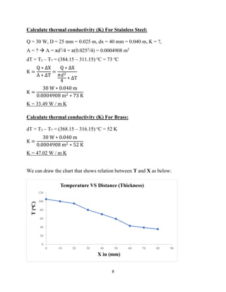
This lab report describes an experiment on linear heat conduction. The experiment was conducted by a group of students to calculate the thermal conductivity of stainless steel and brass. Temperature readings were recorded at different points along the length of each material as heat was applied to one end. The thermal conductivity was then calculated using Fourier's law of heat conduction. The results found that stainless steel has a thermal conductivity of 33.49 W/mK and brass has a thermal conductivity of 47.02 W/mK. A graph was included showing the relationship between temperature and distance for each material.


