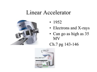
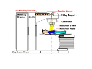
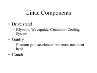
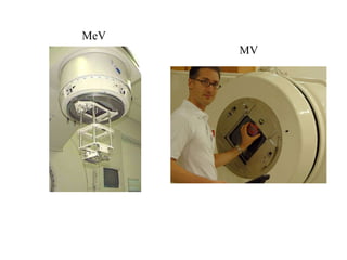
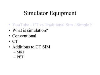
HSC 340 9-7-10 History (Brief overview) Treatment Delivery Equipment Simulation Equipment
History Three aspects that paved the way to discovery of xrays: electricity, vacuums, image recording materials Discovery of x-rays by Wilhelm Roentgen 1895, received Nobel Prize in 1901 Edison experimented with x-rays in 1896 (specifically fluoro), stopped experiments due to damage to colleague Clarence Daly (died in 1904 from radiation side effects) Becquerel discovered radioactivity in 1896 Marie Curie discovered radioactive elements (polonium and radium) in 1898 Radium was then used for the first documented cancer treatment in 1898 Soon replaced by Cobalt and Cesium in mid 1900’s Linacs were developed in 1940
Isodose Curves Isodose lines- lines connecting points of equivalent relative radiation dose Isodose curve- plotted % depth dose at various points in the beam along the CAX and elsewhere
Isodose curve for a 6MV photon beam incident on a flat, homogenous medium
Isodose curves differ according to the surface they are incident upon
They also differ with different densities in tissues, such as air
Isodose curves for different energy beams
kV Treatment  Kilovoltage characteristics Superficial treatment CAX dose and physical penumbra are based on beam quality Ex. the 50% line of a 200kv beam reaches deeper than the 50% line of a 100kv beam Low energy equipment Grenz Contact Superficial Orthovoltage
Grenz 1928 Low energy 10-15kV Superficial Inflammatory disorders, Herpes simplex
Contact 1934 40-50kV Superficial Rectal cancer lower to middle third of rectum
Superficial 1896 50-150kV Superficial Skin no deeper than 5mm
Orthovoltage 1923 150-500 kV Skin, mouth, cervical CA
MV Treatment MV characteristics Energy above 1MV Skin sparing Ability to treat deep tumors γ-ray beams produces by  Radionuclides are included if energy is above  1 MeV High energy equipment Cyclotron Van de Graaff generator Betatron Cobalt 60 unit Linear accelerator
Cyclotron 1928 Charged particle accelerator Neutron and Proton production for clinical use
Van de Graff generator 1937 Electrons and X-rays Therapy 2MV
Betatron 1941 Electrons and X-rays Therapy 6 to more than 40Mev
Cobalt 60 1951 Radioactive source 1.17 MeV and 1.33 MeV
Linear Accelerator 1952 Electrons and X-rays Can go as high as 35 MV Ch.7 pg 143-146
SSD v SAD SSD The distance from the source of radiation the patients skin SAD The distance from the source of radiation to the axis of rotation of the treatment unit


Linac Components Drive stand Klystron, Waveguide, Circulator, Cooling System Gantry Electron gun, accelerator structure, treatment head Couch
Auxiliary components Control Console Modulator cabinet Computers
Linac accessories Block-  usually made of cerrobend (50% bismuth, 26.7% lead, 13.3% tin, 10% cadmium) Wedge MLC Electron Cone Compensator
MeV MV
HDR/LDR Units LDR- 40-200cGy/hour HDR- 1200cGy/hour or 20cGy per min Both utilize a source Iridium, Cesium, Cobalt, and Radium Require an Afterloader Brain, esophagus, rectum, GYN, breast etc.
HDR advantages can be given on outpatient basis Treatment time is short Implant reproducibility is more precise Complete radiation protection exists no general anesthesia or bed rest Ability to treat large volume Increased comfort level
Simulator Equipment YouTube - CT vs Traditional Sim - Simple Sim What is simulation? Conventional CT  Additions to CT SIM MRI PET
What is simulation? Assists in the treatment planning process  Original set-up technique is produced Supine Prone FF vs. HF Process: who would be involved in each? Diagnosis Consultation Simulation Treatment Planning Treatment
Conventional Simulation Fig. 19-7 Mimics treatment machine Enables field delineation Information is obtained using: Fluoroscopy Radiographs Physical measurements
CT Simulation Patient data is obtained using CT “slices” Cost effective for departments: multi-function May have a “virtual simulation” component
Conventional & CT sim order of events Conventional Sim: Field location Target defined Fields are shaped CT Sim: Target defined Fields are shaped
Additions to CT sim MRI PET Both of the above are able to be merged with the CT to help delineate the tumor site as well as other “critical” structures
MRI Utilized for soft tissue imaging
PET  Nuclear medicine technique which produces a three-dimensional image or picture of functional processes in the body

Hsc 340 9 9

  • 1.
    HSC 340 9-7-10History (Brief overview) Treatment Delivery Equipment Simulation Equipment
  • 2.
    History Three aspectsthat paved the way to discovery of xrays: electricity, vacuums, image recording materials Discovery of x-rays by Wilhelm Roentgen 1895, received Nobel Prize in 1901 Edison experimented with x-rays in 1896 (specifically fluoro), stopped experiments due to damage to colleague Clarence Daly (died in 1904 from radiation side effects) Becquerel discovered radioactivity in 1896 Marie Curie discovered radioactive elements (polonium and radium) in 1898 Radium was then used for the first documented cancer treatment in 1898 Soon replaced by Cobalt and Cesium in mid 1900’s Linacs were developed in 1940
  • 3.
    Isodose Curves Isodoselines- lines connecting points of equivalent relative radiation dose Isodose curve- plotted % depth dose at various points in the beam along the CAX and elsewhere
  • 4.
    Isodose curve fora 6MV photon beam incident on a flat, homogenous medium
  • 5.
    Isodose curves differaccording to the surface they are incident upon
  • 6.
    They also differwith different densities in tissues, such as air
  • 7.
    Isodose curves fordifferent energy beams
  • 8.
    kV Treatment Kilovoltage characteristics Superficial treatment CAX dose and physical penumbra are based on beam quality Ex. the 50% line of a 200kv beam reaches deeper than the 50% line of a 100kv beam Low energy equipment Grenz Contact Superficial Orthovoltage
  • 9.
    Grenz 1928 Lowenergy 10-15kV Superficial Inflammatory disorders, Herpes simplex
  • 10.
    Contact 1934 40-50kVSuperficial Rectal cancer lower to middle third of rectum
  • 11.
    Superficial 1896 50-150kVSuperficial Skin no deeper than 5mm
  • 12.
    Orthovoltage 1923 150-500kV Skin, mouth, cervical CA
  • 13.
    MV Treatment MVcharacteristics Energy above 1MV Skin sparing Ability to treat deep tumors γ-ray beams produces by Radionuclides are included if energy is above 1 MeV High energy equipment Cyclotron Van de Graaff generator Betatron Cobalt 60 unit Linear accelerator
  • 14.
    Cyclotron 1928 Chargedparticle accelerator Neutron and Proton production for clinical use
  • 15.
    Van de Graffgenerator 1937 Electrons and X-rays Therapy 2MV
  • 16.
    Betatron 1941 Electronsand X-rays Therapy 6 to more than 40Mev
  • 17.
    Cobalt 60 1951Radioactive source 1.17 MeV and 1.33 MeV
  • 18.
    Linear Accelerator 1952Electrons and X-rays Can go as high as 35 MV Ch.7 pg 143-146
  • 19.
    SSD v SADSSD The distance from the source of radiation the patients skin SAD The distance from the source of radiation to the axis of rotation of the treatment unit
  • 20.
  • 21.
  • 22.
  • 23.
    Linac Components Drivestand Klystron, Waveguide, Circulator, Cooling System Gantry Electron gun, accelerator structure, treatment head Couch
  • 24.
    Auxiliary components ControlConsole Modulator cabinet Computers
  • 25.
    Linac accessories Block- usually made of cerrobend (50% bismuth, 26.7% lead, 13.3% tin, 10% cadmium) Wedge MLC Electron Cone Compensator
  • 26.
  • 27.
    HDR/LDR Units LDR-40-200cGy/hour HDR- 1200cGy/hour or 20cGy per min Both utilize a source Iridium, Cesium, Cobalt, and Radium Require an Afterloader Brain, esophagus, rectum, GYN, breast etc.
  • 28.
    HDR advantages canbe given on outpatient basis Treatment time is short Implant reproducibility is more precise Complete radiation protection exists no general anesthesia or bed rest Ability to treat large volume Increased comfort level
  • 29.
    Simulator Equipment YouTube- CT vs Traditional Sim - Simple Sim What is simulation? Conventional CT Additions to CT SIM MRI PET
  • 30.
    What is simulation?Assists in the treatment planning process Original set-up technique is produced Supine Prone FF vs. HF Process: who would be involved in each? Diagnosis Consultation Simulation Treatment Planning Treatment
  • 31.
    Conventional Simulation Fig.19-7 Mimics treatment machine Enables field delineation Information is obtained using: Fluoroscopy Radiographs Physical measurements
  • 32.
    CT Simulation Patientdata is obtained using CT “slices” Cost effective for departments: multi-function May have a “virtual simulation” component
  • 33.
    Conventional & CTsim order of events Conventional Sim: Field location Target defined Fields are shaped CT Sim: Target defined Fields are shaped
  • 34.
    Additions to CTsim MRI PET Both of the above are able to be merged with the CT to help delineate the tumor site as well as other “critical” structures
  • 35.
    MRI Utilized forsoft tissue imaging
  • 36.
    PET Nuclearmedicine technique which produces a three-dimensional image or picture of functional processes in the body