Downloaded 145 times

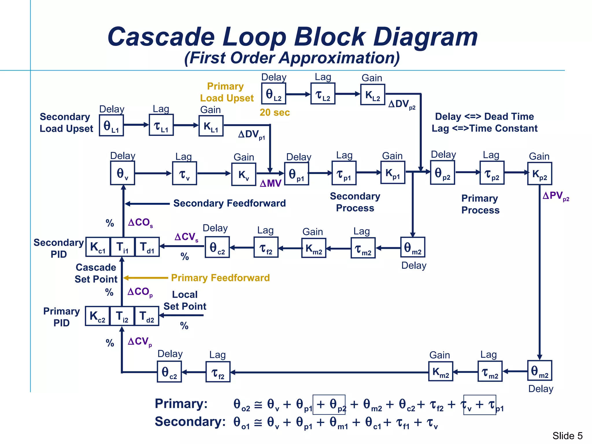
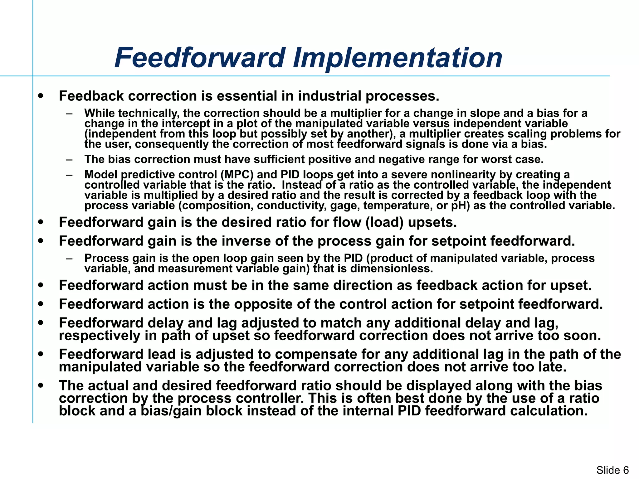
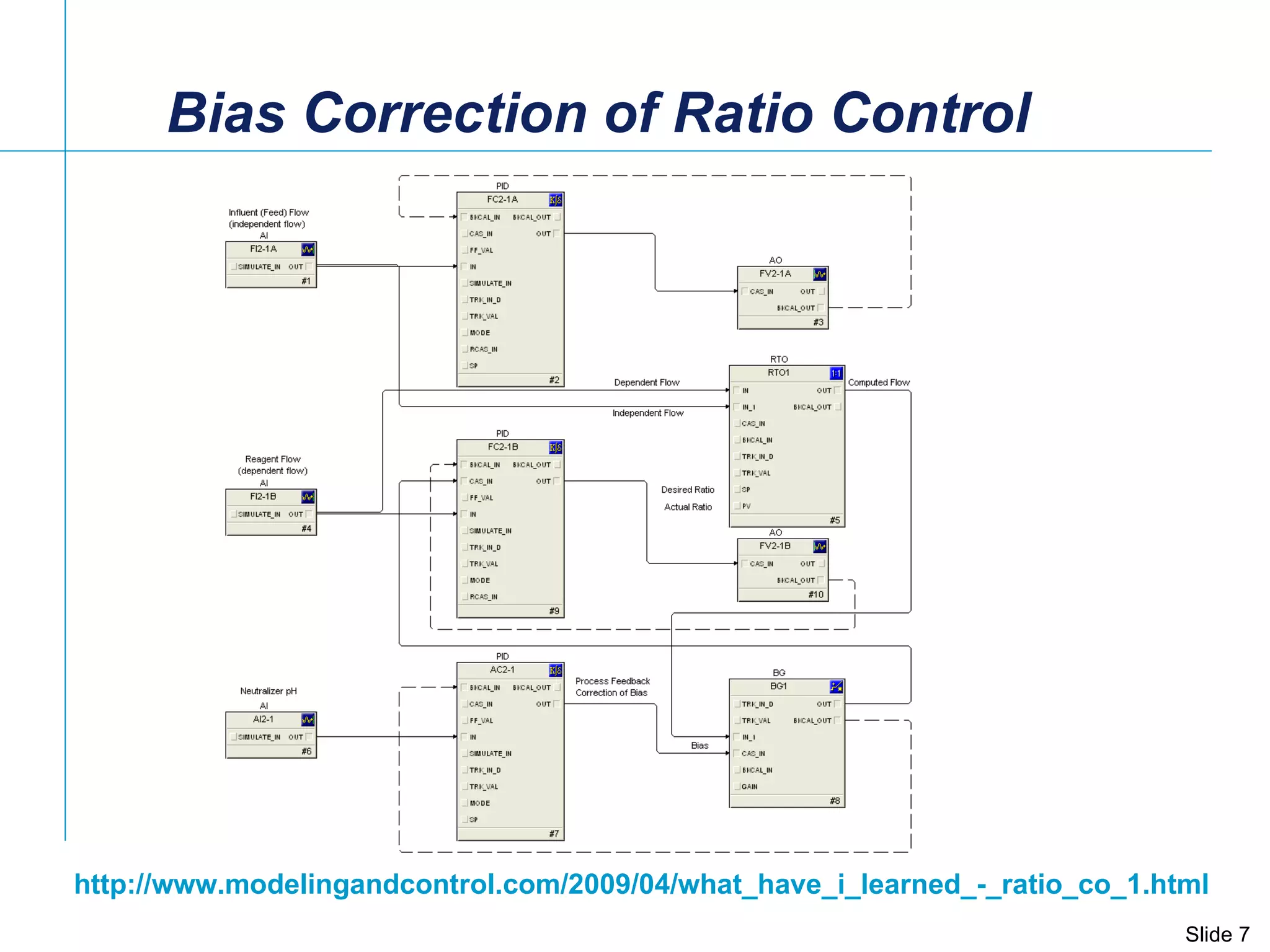
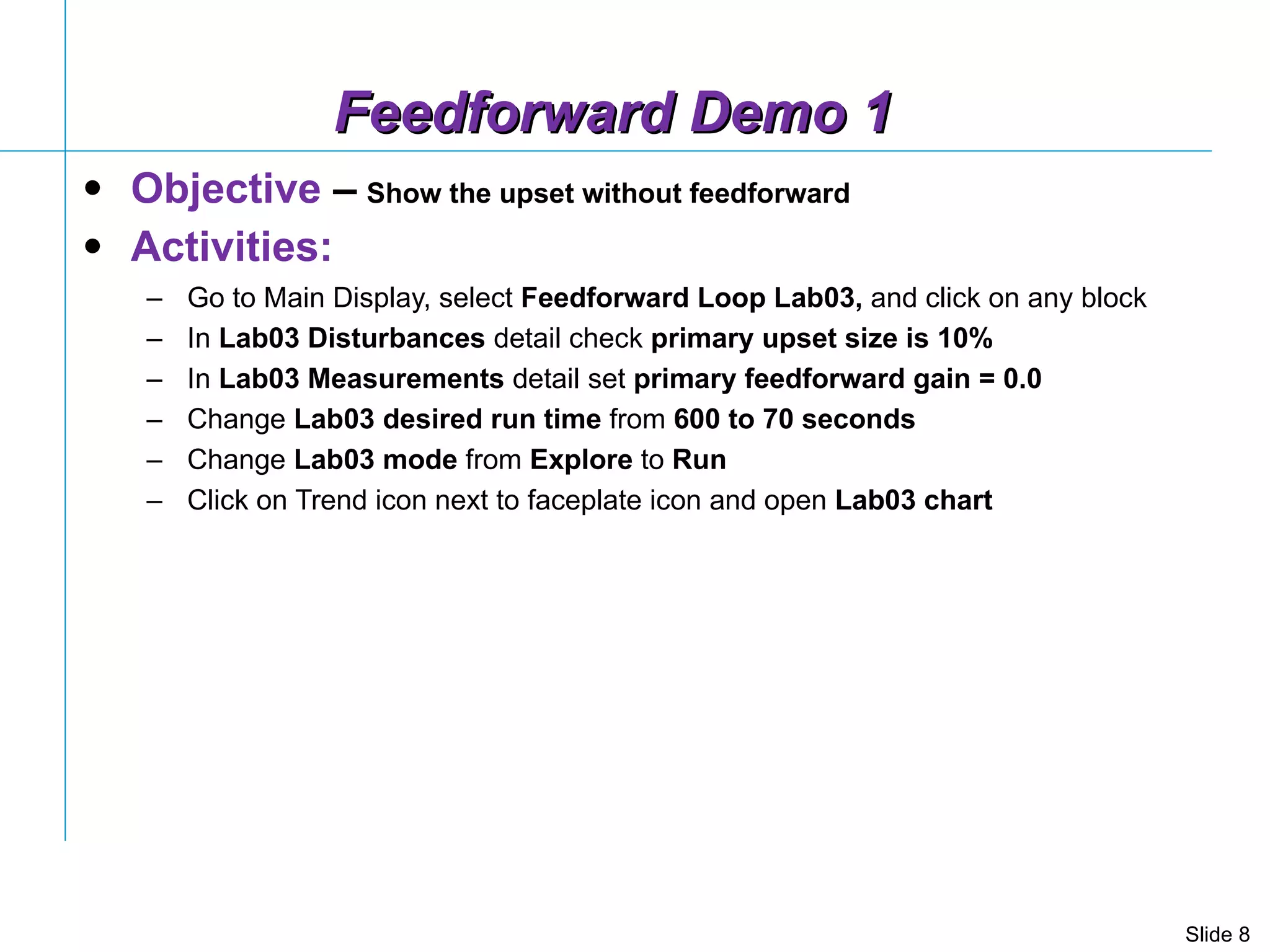
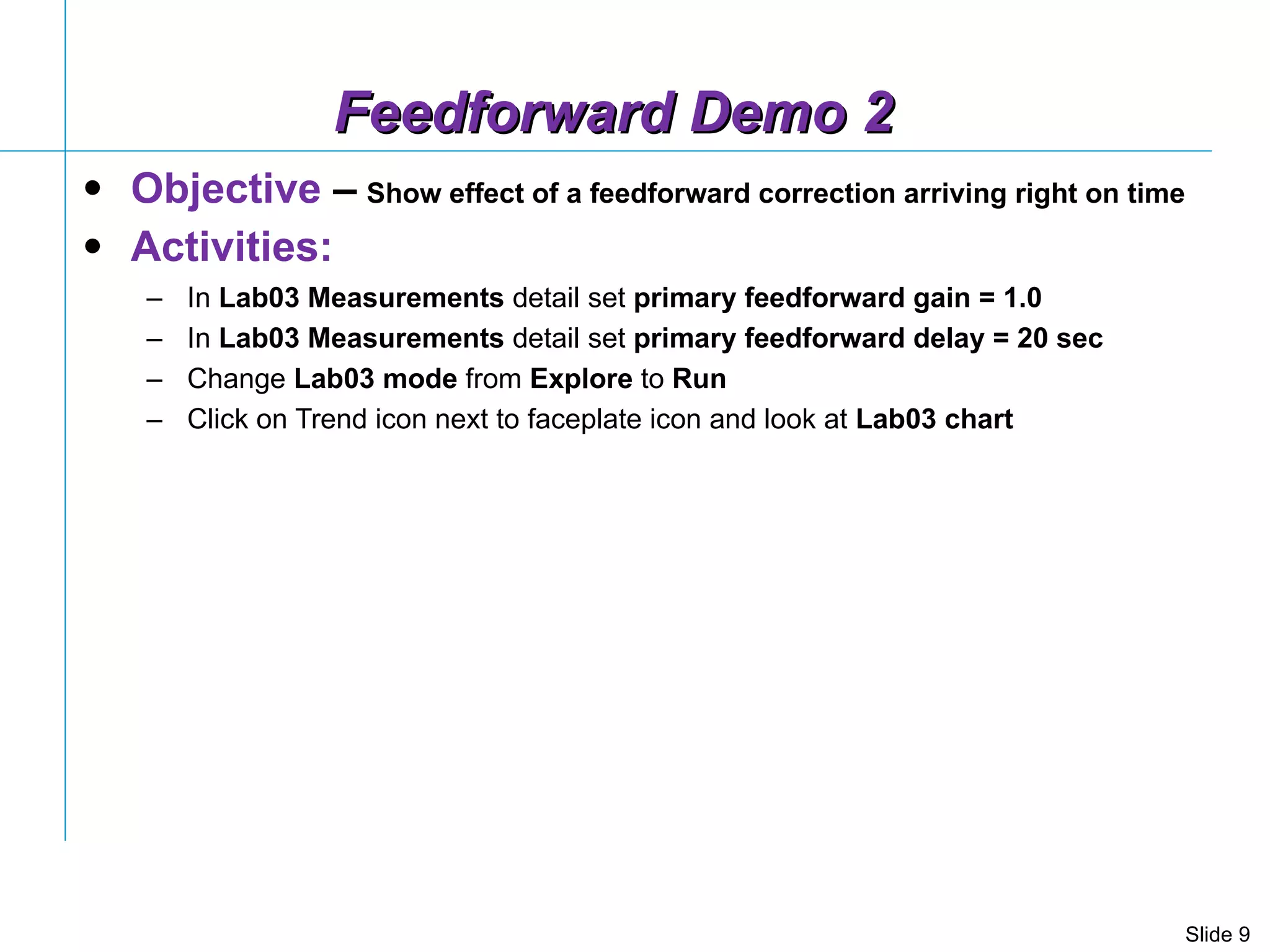
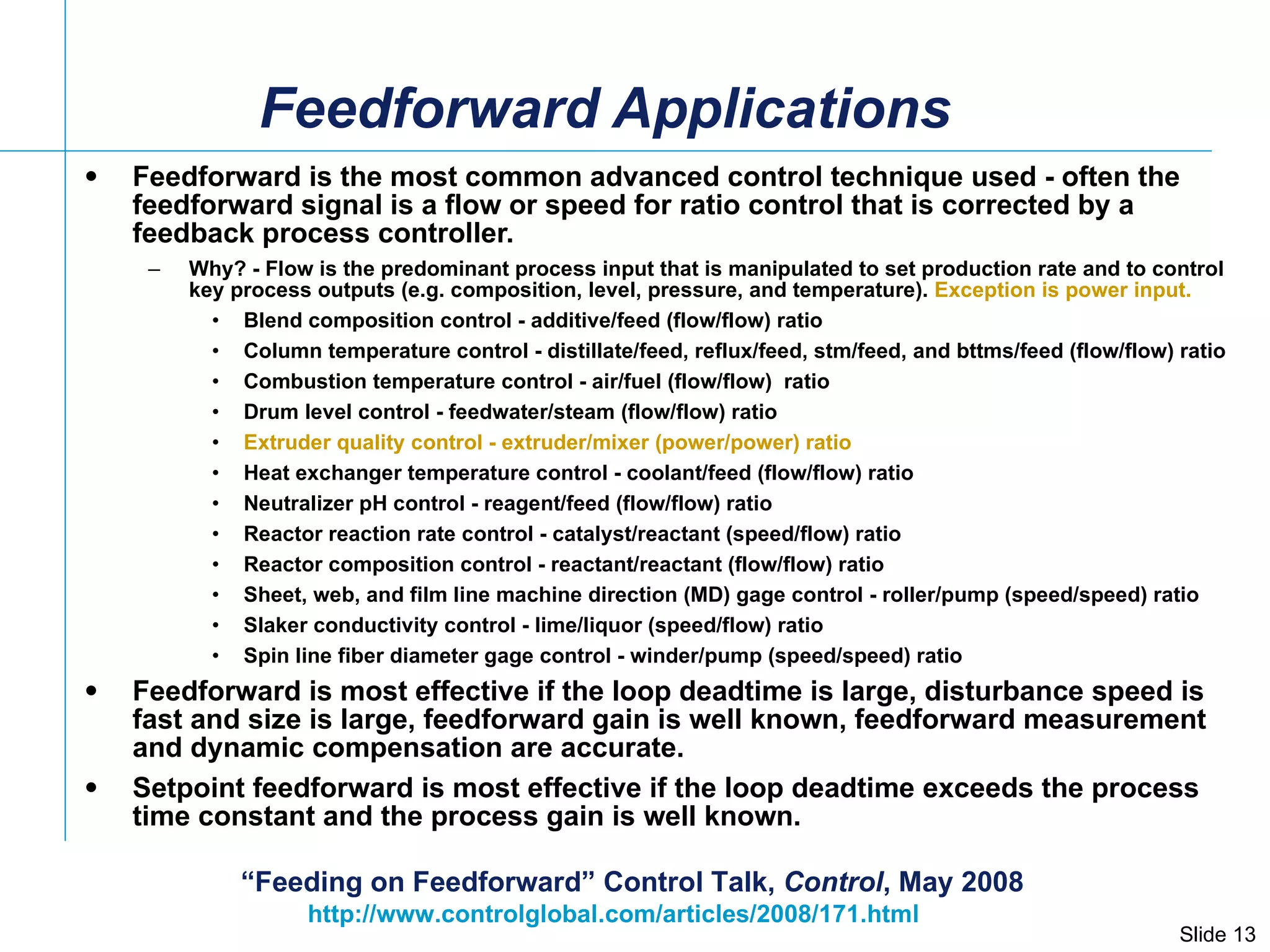
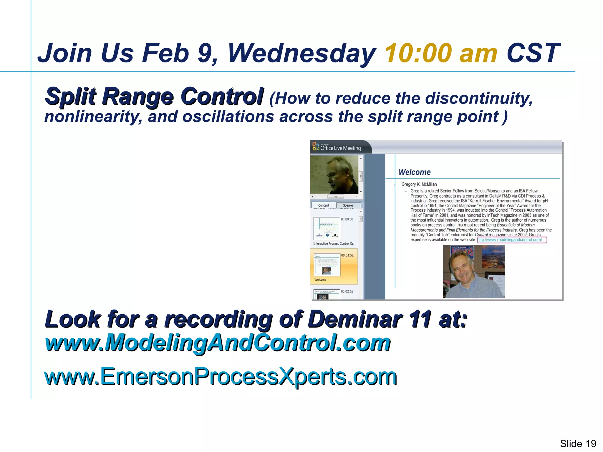

The document provides an overview of a seminar on process control and feedforward control. It introduces the speaker Gregory McMillan and his expertise. It then demonstrates different feedforward control scenarios using process simulation examples. It discusses key considerations for effective feedforward control implementation including ensuring the feedforward correction arrives at the right time.


