SlideShare a Scribd company logo
1 of 52
Download to read offline
Note: Do not use this document to operate the Unit.
Authorized Distributor:
In the interest of product improvement,
specifications are subject to change without notice.
Cat. No. P057-E1-06
Printed in Japan
0709 (0507)
OMRON Corporation
Industrial Automation Company
Regional Headquarters
OMRON EUROPE B.V.
Wegalaan 67-69-2132 JD Hoofddorp
The Netherlands
Tel: (31)2356-81-300/Fax: (31)2356-81-388
OMRON ELECTRONICS LLC
One Commerce Drive Schaumburg,
IL 60173-5302 U.S.A.
Tel: (1) 847-843-7900/Fax: (1) 847-843-7787
OMRON ASIA PACIFIC PTE. LTD.
No. 438A Alexandra Road # 05-05/08 (Lobby 2),
Alexandra Technopark, Singapore 119967
Tel: (65) 6835-3011/Fax: (65) 6835-2711
OMRON (CHINA) CO., LTD.
Room 2211, Bank of China Tower,
200 Yin Cheng Zhong Road,
PuDong New Area, Shanghai, 200120, China
Tel: (86) 21-5037-2222/Fax: (86) 21-5037-2200
OMRON Industrial Automation Global: www.ia.omron.com
Control Devices Division H.Q.
Automation & Drive Division
Automation Department 1
Shiokoji Horikawa, Shimogyo-ku,
Kyoto, 600-8530 Japan
Tel: (81) 75-344-7084/Fax: (81) 75-344-7149
© OMRON Corporation 2009 All Rights Reserved.
Wide Lineup of CPU Units with
USB Port on All Models.
Multi-functionality Condensed
into One-package PLCs
CP1L-L
CP1H
CP1L-M
CP1L-M
CP1L-L
Ethernet Option Board
CP1H/CP1L
A general-purpose USB cable
keeps costs low, including the
cable cost.
Attach an LCD Option Board to the
CPU Unit to easily monitor or
change data values in the PLC to
visually check error status.
The Ultimate High-performance
Package-type PLC
Three types of CPU Unit are available to meet
applications requiring advanced functionality:
•The CP1H-X with pulse outputs for 4 axes.
•The CP1H-Y with 1-MHz pulse I/O.
•The CP1H-XA with built-in analog I/O.
CP1H
CP1L
Programmable
Terminal
Counter Pulse output
3G3MX
or other
Inverter
A Standard Package-type PLC
Complete with a standard-feature USB port, CP1L
CPU Units are available for applications with as few
as 10 I/O points. Whether you need simple sequence
control or pulse I/O and a serial port, the CP1L PLCs
give you an economical choice from among 10-, 14-,
20-, 30-, 40-, and 60-point CPU Units.
Servomotor
or Servo
Driver
Rotary
Encoder
RS-232CRS-485
Example:
SMARTSTEP 2
CP1W-DAM01
LCD Option Board
The Board can be used only
in the option board slot 1.
32
All-in-one Package PLCs with Condensed Multi-functionality.
A Wide Variety of Built-in Functions Expand Application
Capabilities and Shorten the Design Time Required for the Growing
Number and Increasing Complexity of Ladder Programs
Complete Pulse and Serial Functions for Servo and Inverter
Applications and Applications Using Programmable Terminals
For positioning or communications, simply enter the set values
for the instructions. Even complicated functions can be easily
programmed using the OMRON Function Block (FB) Library.
USB Port Standard on all Models
Easy Maintenance and Startup Adjustments with LCD Displays and Settings
Building-block PLCsBuilding-block PLCs
SYSMAC CJ Series
SYSMAC CP Series
SYSMAC CS Series
No Backplane
Backplane Construction
I/O Capacity,
Program Capacity,
Speed
Small-scale Control Large-scale System Control
From small-scale to large-scale
control, programs can be created
incorporating function blocks (FB)
and structured text (ST) using the
same instructions and with the
same easy operation.
(BOOL)
EN
(INT)
NodeNo
(BOOL)
Execute
(REAL)
Velocity
(INT)
Direction
(WORD)
AreaID
(INT)
AreaNo
(BOOL)
ENO
(BOOL)
InVelocity
(BOOL)
CommandAborted
(BOOL)
Error
(WORD)
ErrorID
_INV032_MoveVelocityHz
Speed coincidence
Abort
Error
Error code
Always ON
Inverter No.
Execute
Frequency
Rotation direction
Area
Area No.
Pulse outputs
CP1H/CP1L
Note: For details on the R7D-B Series,
refer to page 64.
Inverter
RS-485
(BOOL)
EN
(INT)
Axis
(BOOL)
Execute
(REAL)
Position
(REAL)
Velocity
(REAL)
Acceleration
(REAL)
Deceleration
(INT)
OutPulseSelect
(BOOL)
ENO
(BOOL)
Done
(BOOL)
Busy
(BOOL)
Error
(WORD)
ErrorID
_INCCP1H010_MoveAbsolute_REAL
End positioning
Busy Flag
Error Flag
Error code
(Can be omitted.)
Always ON (P_On)
Axis No.
Execute
Position command
Speed command
Acceleration rate
Deceleration rate
Pulse output method
OMRON Function Block
for 3G3RV or 3G3MV RS-485
Communications
OMRON Function Block for
Pulse Output Positioning
Servo Driver
Example: SMARTSTEP 2, R7D Series, etc.
Inverter
CP-series Lineup...................
Expandability
Applications.........................
CPU Units.............................
Expansion Units.................
Functions.............................
Pulse Outputs.......................
High-speed Counters.................
Inverter Positioning...................
Serial Communications.......
Ethernet Communications...
Analog I/O.............................
USB Peripheral Port.............
LCD Displays and Settings...
Support Software...............
CPU Unit Functions............
Connecting Expansion Unit
and Expansion I/O Units.......
CPU Unit Specifications.....
Option Unit Specifications...
Expansion I/O Unit
Specifications.....................
Expansion Unit
Specifications.....................
Dimensions.........................
Instructions.........................
Ordering Information.........
OMRON Function Block
Library.................................
SMARTSTEP 2
AC Servo Drivers with
Pulse String Inputs.............
4
6
8
10
12
12
14
15
16
18
19
20
21
22
24
26
28
43
44
46
48
51
55
62
64
Package PLCsPackage PLCs
FA Integrated Tool Package
Cannot be used for the CP1L-L10.
CP1L-L14D - CP1L-L20D -
High-speed Positioning Built-in Analog I/O
A Choice of Three Types of CP1H CPU Unit Lets You Select the Functions You Need.
Two axes at 1 MHz and two axes at 100 kHz Four axes at 100 kHz
Four analog inputs and
two analog outputs
Four axes at 100 kHz for single-phase
(50 kHz for differential phases)
RS-232C
Option Board
LCD
Option Board
RS-422A/485
Option Board
CP1H-Y CPU Units CP1H-XA CPU Units
StandardType
CP1H-X CPU Units
Pulse Outputs
for 4 Axes
High-speed
Counters for
4 Axes
Built-in
Analog I/O
Serial
Communications
CP-series Lineup
A program capacity of 20K steps and 0.1 μs high-speed processing provide
multi-axis, high-speed positioning control or analog control. CJ-series Special
I/O Units and CPU Bus Units can also be used.
Basic package PLCs with serious functions from simple sequence control
to 2-axis positioning control.
Two axes at 1 MHz for single-phase (500 kHz for
differential phases) and two axes at 100 kHz for
single-phase (50 kHz for differential phases)
Up to two Option Boards can be mounted.
CP1H- 40D -
CP1L-M30D -
CP1L-L10D -
CP1L-M40D - CP1L-M60D -
90 mm
86 mm
85 mm
90 mm
66 mm
85 mm
90 mm
86 mm
85 mm
130 mm
85 mm
90 mm
85 mm
90 mm
150mm 85 mm
90 mm
195 mm
Program capacity
Processing speed
I/O capacity
LCD Display
Settings One LCD Option Board can be mounted in option board slot 1.
Ethernet
Option Board
Ethernet
Communications One Ethernet Option Board can be mounted in an option board slot.
54
A Wide Range of CPU Units Allows You to Select the Ideal Model.
10 points 14 points 20 points
Pulse Outputs
Four-axis control is a standard feature.
USB Peripheral Port
Another standard feature.
LCD Displays and Settings
Enabled using Option Board.
Ethernet Communications
Enabled by using an Option Board.
Serial Communications
Two ports. Select Option Boards for either RS-232C or
RS-485 communications.
Built-in Analog I/O
XA CPU Units provide 4 input words and 2 output words.
Counters
Four-axis differential-phase control is
a standard feature.
Serial Communications
Two ports (See note.). Select Option Boards for either RS-232C or
RS-485 communications.
LCD Displays and Settings
Enabled using Option Board. (See note.)
Counters with 2-axis differential-
phase control are standard features.
Single-phase: 4 axes at 100 kHz
Note: CP1L-L CPU Units with 14 and 20 points support only one port.
Cannot be used for the CP1L-L10.
Note: Cannot be used for the CP1L-L10.
85 mm
CP1H Series
CP1L Series
Program capacity
20K steps
Processing speed
0.1 μs
(basic instructions)
Program capacity
10K steps
Processing speed
0.55 μs
(basic instructions)
Program capacity
5K steps
Processing speed
0.55 μs
(basic instructions)
90 mm
150 mm
30 points 40 points 60 points
Pulse Outputs
Two-axis control at 100 kHz is
a standard feature.
USB Peripheral Port
Another standard feature.
Ethernet Communications
Enabled by using an Option Board.
Using Only CP1W Units with the CP1H
CP1W/CPM1A Expansion Units and Expansion I/O Units and CJ Units can be used simultaneously.
CP1W-CN811 I/O Connecting Cable is required.
Note: Some Expansion Units and Expansion I/O Units have certain restrictions on use.
(For details, refer to page 24.)
Up to 7 CP1W/CPM1A Expansion Units and Expansion I/O Units can be connected.
CP1H Application Examples
CP1L-M30D - /CP1L-M40D - /CP1L-M60D -
CP1L-L14D - /CP1L-L20D -
Capacitor picking
Process
depth Process
positioning
Rotation
(final positioning)
Forming Machine Electronic Parts Assembly
Machine
Spinning Machine Packing Machine Air Cleaner Control Shopping Mall Fountain Control
Four-axis, 1-MHz High-speed
Pulse Outputs
Built-in Analog I/O:
4 Analog Inputs and 2 Analog Outputs
4-axis, 1-MHz High-speed Counters
CP1H-XA CPU Unit Temperature Sensor Unit
4 analog inputs and
2 analog outputs
Hydraulic pressure control
High-speed counters
Thread winding speed
and length control
Cleaner fan motor control
(Inverter)
Pulse
outputs
Positioning control
via Servomotors
CJ Unit Adaptor
CP1W-EXT01
CP1H-Y CPU Unit
Pulse
outputs
Sheet feeding
control via
Servomotors
CP1L
CP1L CP1LAnalog Output Unit
Using CJ-series Special I/O Units, CJ-series CPU Bus Units, and CP1W Units with the CP1H
Up to 7 CP1W/CPM1A Expansion Units and Expansion I/O Units can be connected.
Up to two CJ-series CPU Bus Units or Special I/O Units can
be connected.
Up to three CP1W/CPM1A Expansion Units
and Expansion I/O Units can be connected.
One CP1W/CPM1A Expansion Unit or Expansion I/O Unit can be connected.
CP1L Application Examples
CP1H/CP1L Communications Interface Options
CP1H-Y CPU Unit
76
Expansion Units Provide for a Wider Range of Applications.
Two Optional Serial Ports
Two Optional Ethernet Ports
Option Boards
RS-232C
Interface
CP1W-ClF01
CP1H/CP1L
Standard Feature:
USB peripheral port
Note: Only one board is supported by CP1L-L CPU Units (14 or 20 points).
Cannot be used for the CP1L-L10.
RS-422A/485
Interface
CP1W-ClF11
RS-422A/485
(Isolated-type) Interface
CP1W-ClF12
Ethernet
Interface
CP1W-CIF41
Two types of communications are available.
Only one Ethernet port can be used.
Either two RS-232C ports or two
RS-422A/485 ports can be used.
Expandability
Applications
Two-axis Pulse Outputs Sequence Control Sequence Control with Clock Function
Note: Cannot be used for the CP1L-L10.
LCD
Two serial ports can be added as options
(either RS-232C or RS-422A/485 Option Boards).
One Ethernet port can be added as an option.
98
CP1H CP1L
CP1L-L10DR-A
AC power supply,
6 DC inputs, 4 relay outputs
CP1L-L10DT-A
AC power supply, 6 DC inputs,
4 transistor (sinking) outputs
CP1L-L10DR-D
DC power supply,
6 DC inputs, 4 relay outputs
CP1L-L10DT-D
DC power supply, 6 DC inputs,
4 transistor (sinking) outputs
CP1L-L10DT1-D
DC power supply, 6 DC inputs,
4 transistor (sourcing) outputs
CP1L-M60DR-A
AC power supply,
36 DC inputs, 24 relay outputs
CP1L-M60DT-A
AC power supply, 36 DC inputs,
24 transistor (sinking) outputs
CP1L-M60DR-D
DC power supply,
36 DC inputs, 24 relay outputs
CP1L-M60DT-D
DC power supply, 36 DC inputs,
24 transistor (sinking) outputs
CP1L-M60DT1-D
DC power supply, 36 DC inputs,
24 transistor (sourcing) outputs
CPU Units
Maximize Efficiency by Selecting the Optimum CPU Unit for Your Applications.
Pulse outputs
(only for transistor outputs)
Counters
Serial
communications
Ethernet
communications
USB
peripheral port
Built-in analog I/O
Memory Cassette
LCD display settings
Function blocks
(ladder diagrams or
ST language)
Inverter positioning
7-segment display
Program capacity
Data memory
capacity
High-speed
processing
Y CPU Units XA CPU Units X CPU Units M Type 60 Points
CP1H-Y20DT-D
DC power supply, 12 DC inputs,
8 transistor (sinking) outputs
Two line-driver inputs
Two line-driver outputs
CP1H-XA40DR-A
AC power supply, 24 DC inputs,
16 relay outputs, 4 analog inputs,
2 analog outputs
CP1H-XA40DT-D
DC power supply, 24 DC inputs,
16 transistor (sinking) outputs,
4 analog inputs, 2 analog outputs
CP1H-XA40DT1-D
DC power supply, 24 DC inputs,
16 transistor (sourcing) outputs,
4 analog inputs, 2 analog outputs
CP1H-X40DR-A
AC power supply, 24 DC inputs,
16 relay outputs
CP1H-X40DT-D
DC power supply, 24 DC inputs,
16 transistor (sinking) outputs
CP1H-X40DT1-D
DC power supply, 24 DC inputs,
16 transistor (sourcing) outputs
CP1L-M40DR-A
AC power supply, 24 DC inputs,
16 relay outputs
CP1L-M40DT-A
AC power supply, 24 DC inputs,
16 transistor (sinking) outputs
CP1L-M40DR-D
DC power supply, 24 DC inputs,
16 relay outputs
CP1L-M40DT-D
DC power supply, 24 DC inputs,
16 transistor (sinking) outputs
CP1L-M40DT1-D
DC power supply, 24 DC inputs,
16 transistor (sourcing) outputs
CP1L-M30DR-A
DC power supply, 18 DC inputs,
12 relay outputs
CP1L-M30DT-A
AC power supply, 18 DC inputs,
12 transistor (sinking) outputs
CP1L-M30DR-D
DC power supply, 18 DC inputs,
12 relay outputs
CP1L-M30DT-D
DC power supply, 18 DC inputs,
12 transistor (sinking) outputs
CP1L-M30DT1-D
DC power supply, 18 DC inputs,
12 transistor (sourcing) outputs
CP1L-L20DR-A
AC power supply, 12 DC inputs,
8 relay outputs
CP1L-L20DT-A
AC power supply, 12 DC inputs,
8 transistor (sinking) outputs
CP1L-L20DR-D
DC power supply, 12 DC inputs,
8 relay outputs
CP1L-L20DT-D
DC power supply, 12 DC inputs,
8 transistor (sinking) outputs
CP1L-L20DT1-D
DC power supply, 12 DC inputs,
8 transistor (sourcing) outputs
100 KHz for four axes
100 kHz (single-phase), 50 kHz (differential phases)
1 MHz (single-phase), 500 kHz
(differential phases) for two axes
(line driver outputs), 100 kHz (single-
phase), 50 kHz (differential phases)
for two axes (four axes total)
1 MHz for two axes
(line driver outputs),
100 kHz for two axes
(four axes total)
100 kHz for two axes
100 kHz (single-phase) for four axes, or 50 kHZ (differential phases) for two axes
Two optional serial ports can be added
(either RS-232C or RS-422A/485 Option Boards).
One Ethernet port can be added as an option. One Ethernet port can be added as an option.
One optional serial port can be added
(either an RS-232C or RS-422A/485 Option Board).
5K steps
10K words
Yes Yes
Yes
Yes
Yes
Yes
Yes
Yes
Yes
Yes
Yes
Yes
Yes
Yes
Yes
Yes
Yes
Yes
Yes
Yes
Yes
Yes
Yes
Yes
Yes
Yes
An LCD Option Board can be added as an option to option board slot 1.
YesYes
Yes
Yes
Yes
Yes
Yes
Yes
Yes
Yes
10K steps
32K words
0.55 μs/LD instruction, 1.84 μs/MOV instruction
20K steps
32K words
0.1 μs/LD instruction, 0.3 μs/MOV instruction
4 analog inputs and
2 analog outputs
(resolution: 6,000 or 12,000)
M Type 40 Points M Type 30 Points L Type 20 Points L Type 14 Points L Type 10 Points
CP1L-L14DR-A
AC power supply, 8 DC inputs,
6 relay outputs
CP1L-L14DT-A
AC power supply, 8 DC inputs,
6 transistor (sinking) outputs
CP1L-L14DR-D
DC power supply, 8 DC inputs,
6 relay outputs
CP1L-L14DT-D
DC power supply, 8 DC inputs,
6 transistor (sinking) outputs
CP1L-L14DT1-D
DC power supply, 8 DC inputs,
6 transistor (sourcing) outputs
An LCD Option Board can be added as
an option to option board slot 1.
An LCD Option Board can be added as
an option to option board slot 1.
Expansion Units
CP1W-20EDR1
•12 DC inputs
•8 relay outputs
CP1W-16ER
•16 relay outputs
CP1W-20EDT
•12 DC inputs
•8 transistor outputs
(sinking)
CP1W-20EDT1
•12 DC inputs
•8 transistor outputs
(sourcing)
CP1W-40EDR
•24 DC inputs
•16 relay outputs
CP1W-40EDT
•24 DC inputs
•16 transistor outputs (sinking)
CP1W-40EDT1
•24 DC inputs
•16 transistor outputs (sourcing)
CP1W-8ED
•8 DC inputs
CP1W-8ER
•8 relay outputs
CP1W-8ET
•8 transistor outputs
(sinking)
CP1W-8ET1
•8 Transistor outputs
(sourcing)
CompoBus/S I/O Link Unit
CP1W-SRT21
•Inputs: 8
•Outputs: 8
CP1W-CN811 I/O Connecting Cable: 80 cm
Note: CP1W/CPM1A Expansion Units include I/O
Connection Cables (in lengths of approx. 6 cm) for
side-by-side connection.
10 11
Options
Option Boards
CP1H and CP1L
CP1H Only
I/O Connecting
Cable
Up to two CJ-series Special I/O Units or CPU Bus Units can be connected by using a CJ Unit Adaptor.
Refer to page 27 for the Units that can be used. For details on CJ-series Units, refer to the CJ1 Catalog (Cat. No. P052).
RS-232C
Option Board
CP1W-ClF01
RS-422A/485
Option Board
CP1W-ClF11
Memory Cassette
CP1W-ME05M
CJ Unit Adaptor
CP1W-EXT01
(with End Cover)
Position Control Units
CJ1W-NC 3
(1 to 4 axes)
Position Control Unit with
MECHATROLINK-II
Communications
CJ1W-NC271 (2 axes)
CJ1W-NC471 (4 axes)
CJ1W-NCF71 (16 axes)
CJ1W-NCF71-MA (16 axes)
Motion Control Unit with
MECHATROLINK-II
Communications
CJ1W-MCH71 (30 axes)
SYSMAC SPU
High-speed Data
Collection Unit
CJ1W-SPU01-V2
Controller Link Unit
CJ1W-CLK23
FL-Net Unit
CJ1W-FLN22
(100Base-TX)
DeviceNet Unit
CJ1W-DRM21
EtherNet/IP Unit
CJ1W-EIP21
Ethernet Unit
CJ1W-ETN21
(100Base-TX)
Serial Communications
Units
CJ1W-SCU41-V1
(RS-232C and RS-422/485
ports)
CJ1W-SCU21-V1
(Two RS-232C ports)
CJ1W-SCU31-V1
(Two RS-422/485 ports)
High-speed Counter Unit
CJ1W-CT021
(2 axes)
ID Sensor Units
CJ1W-V680C1
CJ1W-V600C1
(1 or 2 Heads)
CompoBus/S
Master Unit
CJ1W-SRM21
Analog Output Units
CJ1W-DA021/041
CJ1W-DA08V/08C
(2, 4, or 8 points)
Analog Input Units
CJ1W-AD041-V1
CJ1W-AD081-V1
(4 or 8 points)
Analog I/O Unit
CJ1W-MAD42
(4 analog inputs,
2 analog outputs)
Process Input Units
CJ1W-PH41U
CJ1W-AD04U
CJ1W-PTS51/52
CJ1W-PTS15/16
CJ1W-PDC15
Temperature Control
Units
CJ1W-TC
(4 or 2 loops)
Temperature Sensor Unit
CJ-series Special I/O Units and CPU Bus Units
CPM1A
Expansion
Unit and
Expansion
I/O Units
CompoBus/S I/O
Link Unit
Expansion I/O Units Analog Units
Temperature Sensor Unit
CP1W-TS001
•Thermocouple inputs: 2
CP1W-TS002
•Thermocouple inputs: 4
Temperature Sensor Unit
CP1W-TS101
•Platinum-resistance thermometer inputs: 2
CP1W-TS102
•Platinum-resistance thermometer inputs: 4
CPM1A Expansion Unit and
Expansion I/O Units can be
used with CP1H or CP1L CPU
Units under the same
conditions as for the CP1W.
Special I/O Units
CPU Bus Units
Analog Input Unit
CP1W-AD041
•Analog inputs: 4 (resolution: 6,000)
Analog Output Unit
CP1W-DA041
•Analog outputs: 4 (resolution: 6,000)
Analog I/O Unit
CP1W-MAD11
•Analog inputs: 2 (resolution: 6,000)
•Analog outputs: 1 (resolution: 6,000) Analog Input Units
CJ1W-ADG41
(4 points)
CompoNet Master Unit
CJ1W-CRM21
CP1W-32ER
•32 relay outputs
CP1W-32ET
•32 transistor outputs (sinking)
CP1W-32ET1
•32 transistor outputs (sourcing)
CP1W-16ET
•16 transistor outputs
(sinking)
CP1W-16ET1
•16 transistor outputs
(sourcing)
LCD Option
Board
CP1W-DAM01
Ethernet Option
Board
CP1W-CIF41
RS-422A/485
(Isolated-type)
Option Board
CP1W-ClF12
CP1W-series and CJ-series Units Can Be Use d for Maximum Expandability
Example: Four-axis Control in Electronic
Component Manufacturing Equipment
Up to Four Axes Are Standard.
Advanced Power for High-precision Positioning Control.
Positioning for Electronic Component
Manufacturing Equipment
Pulse Outputs
Pulse Output Function for Up to Four Axes.
Along with greater precision and more flexibility in
multi-product manufacturing, high-speed multi-axis pulse
output control responds to the increase in servo applications.
Capacitor removal
Processing
depth Processing
positioning
Rotation (final positioning)
A Full Range of Functions
Programming Is Made Easy Using OMRON Function Blocks
Applicable CPU Units and Functions
Positioning with Trapezoidal Acceleration and
Deceleration (PLS2 Instruction)
Origin Search Function (ORG Instruction)
Stop after output of
set number of pulses
PLS2 executed
Speed control
(ACC instruction)
Feed Control for
Packing Material
Target speed control
Specified number
of travel pulses
Acceleration
Start
frequency
Deceleration
S-curve
acceleration
S-curve
deceleration
Easily achieved with
special positioning
instruction (PLS2).
S-curve acceleration/
deceleration can be
used to reduce vibration
in high-speed positioning.
The packing material is fed
and stopped at a fixed position
after the seal mark is detected.
Origin searches are possible with a single ORG instruction.
12 13
CP1H
Servo
Drivers
Pulse outputs
Servomotors
1 MHz for 2 axes and 100 kHz for
2 axes, for a total of 4 axes
100 kHz for 4 axes
CP1H-X CPU Unit
100 kHz for 2 axes
CP1L CPU UnitCP1H-Y CPU Unit
Servo
Driver
CW/CCWPulse output
CP1H/CP1L
Just use the CX-Programmer to paste function blocks into the ladder program.
Example: Using Positioning OMRON Function Block
1 2 3
Position command
200,000 pulses
Acceleration rate
100 Hz/4 ms
Deceleration rate
100 Hz/4 ms
Speed: 50,000 Hz
CW
Position command
200,000 pulses
Acceleration
rate
100 Hz/4 ms
Deceleration
rate
100 Hz/4 ms
Speed
1,000 Hz/4 ms
Speed: 50,000 Hz
Interrupt input signal 00 (Input word 0, bit 00)
SMARTSTEP 2,
R7D Series, Etc.
Always ON (P-On)
Start trigger
Bit A
Always ON (P-On)
Start trigger
Bit A
Bit A Bit A
Bit DBit B Bit DBit B
End positioning
Bit B
Busy Flag
Bit C
Error Flag
Bit D
Error code
(Can be omitted.)
-NCCP1H010-MoveAbsolute-REAL
(BOOL)
EN
(INT)
Axis
(BOOL)
Execute
(REAL)
Position
(REAL)
Velocity
(REAL)
Acceleration
(REAL)
Deceleration
(INT)
OutPulseSelect
(BOOL)
ENO
(BOOL)
Done
(BOOL)
Busy
(BOOL)
Error
(WORD)
ErrorID
Axis No.
Pulse output 0: &0
Start
Bit A
Position command
200,000 pulses: +200,000.0
Speed command
50,000 Hz: +50,000.0
Acceleration rate
100 Hz/4 ms: +100.0
Deceleration rate
100 Hz/4 ms: +100.0
Pulse output method
CW/CCW: &0
Axis No.
Pulse output 0: &0
Start
Bit A
Interrupt input selection
0.00
Interrupt position
D0
Interrupt feeding amount
200,000 pulses: +200,000.0
Speed command -1
5,000 Hz: +5,000.0
Speed command - 2
1,000 Hz: +1,000.0
Acceleration rate
100 Hz/4 ms: +100.0
Deceleration rate
100 Hz/4 ms: +100.0
Pulse output method
CW/CCW method: &0
End positioning
Bit B
Operating status
D10
Processing Flag
Bit C
Error Flag
Contact D
Error Flag
(Can be omitted.)
-NCCP1H110-MoveInterrupt-REAL
(BOOL)
EN
(INT)
Axis
(BOOL)
Execute
(BOOL)
InterruptSelect
(DINT)
InterruptPosition
(REAL)
Distance
(REAL)
Velocity-1
(REAL)
Velocity-2
(REAL)
Acceleration
(REAL)
Deceleration
(INT)
OutPulseSelect
(BOOL)
ENO
(BOOL)
Done
(INT)
Status
(BOOL)
Busy
(BOOL)
Error
(WORD)
ErrorID
Reads High-speed Counter PV.
#0000
#0000
DO
PRV(881)
Always ON (P-On)
Interrupt Task 140
Interrupt input 0 (0.00)
Rightmost word of output
destination
Control data
Port designation
Pulse Outputs
Sheet Feeding for Vertical Pillow Packer
Interrupt Feeding (ACC and PLS2 Instructions)
Just insert set values into the OMRON Function Block.
Start the CX-Programmer and
right-click "Function Block" in
the tree to select the required
library file.
Use a function block call to select the
desired OMRON Function Block.
An instance of the function block
will be created in the ladder
program.
Using Interrupt Feeding OMRON Function Block
A positioning OMRON Function Block for the CP1H is used in the
above application example.The positioning OMRON Function Blocks
for the CP1L are the same as the positioning OMRON Function Blocks
for the CJ1M-CPU21/22/23.
Note: For a list of function blocks in the OMRON Function Block Library, refer to page 62.
Inverter speed
Inverter speed
(command sent
via RS-485)
Run/stop
command
Low speed
command
Inverter Positioning
High-speed Counters
Differential Phases for Up to Four Axes Are Standard.
Easily Handles Multi-axis Control with a Single Unit.
High-speed Counters
14 15
High-speed Positioning
Operations Using Inverters Is Made Easy.
Inverter Positioning
The deceleration position must
be calculated from the stop
position and the speed.
Operation is simplified, with no
need to calculate the deceleration
position!
To avoid position error, positioning
must be stopped from a low speed.
Positioning becomes unreliable if
stopped from a high speed.
CP1L CPU Unit
High-speed counter
High-speed counter
Calculations are made in
the ladder program based
on high-speed counter
values.
Positioning
command1
1
2
3
Ladder programError counter
Even without going to low speed,
positioning is accurate!
With no need for low speed,
positioning is faster!
Overview of Inverter Positioning
The CP1L's built-in error counter function enables the following operation.
Positioning commands are executed by means of pulse output
instructions. Pulse output instructions normally output pulses from the
PLC, but pulses can be output to the error counter according to the
operand setting in the instruction (such as PLS2).
2 The amount of pulses input to the error counter is converted to a speed
command and output to the inverter. A command to the inverter is created
in the ladder program using this speed command (proportional to the
pulses remaining in the error counter). When RS-485 communications are
executed, ladder programming for communicating with the inverter is
created. When analog outputs are executed, ladder programming for
analog outputs is created.
3 When a run/stop command is executed for the inverter, the motor is
rotated and feedback pulses (for the amount of movement) are output from
the encoder to the CP1L.The error counter value is decremented by these
feedback pulses.The CP1L continues sending commands to the inverter
until positioning is completed.This enables accurate positioning to the
position output by the first position command.
Rotary
encoder
General-
purpose
motor
Rotary
encoder
General-
purpose
motor
Rotary
encoder
General-
purpose
motor
Inverter
Inverter
Inverter
I/O
RS-485/analog output
Feedback pulses
Example: Machinery Such As Ceramics
Conveyor Equipment
RS-485
Inverters
Example: Main-axis Control for
Equipment Such as Spinning
Machines
CP1H
CPU Unit
High-speed counters
RS-485
Applicable CPU Units and Functions
CP1H-X CPU Unit CP1L CPU UnitCP1H-Y CPU Unit
Applicable CPU Units and Functions
Inverter positioning function
for two axes
CP1L CPU Unit
CP1L
Previously Now
Main-axis Control for Equipment Such as
Textile Machinery or Spinning Machinery Machinery Such As Ceramics Conveyor Equipment
Positioning Conveyance for Equipment Such as Building
Material Manufacturing Machinery and Stone-cutting Machinery
Four-axis Counter Function (Single-phase or Differential Phases)
Multi-axis counter inputs enable calculations for inverter positioning, spindle speed control in
textile manufacturing, and much more.
1 MHz (single-phase), 500 kHz
(differential phases) for two axes,
100 kHz (single-phase), 50 kHz
(differential phases) for two axes
(four axes total)
100 kHz (single-phase),
50 kHz (differential phases)
for four axes
100 kHz (single-phase) for
four axes, or 50 kHZ (differential
phases) for two axes
Applicable CPU Units and Functions
A Standard USB Port and Two Serial Ports Enable Connecti ons and
Communications with a Wide Range of Components.
Serial Communications
16 17
Up to two Option Boards can be mounted for RS-232C or RS-422A/485 communications. A peripheral
USB port has been added to connect to a personal computer for a total of three communications ports,
making it easy to simultaneously connect to a PT, various components (such as Inverters, Temperature
Controllers, and Smart Sensors), Serial PLC Link for linking to other PLCs, and a personal computer.
CP1H/CP1L
CPU Unit
CP1H/CP1L CPU Unit
(except CP1L-L10)
CP1H/CP1L
CPU Unit
CP1H/CP1L
CPU Unit
Devices such as OMRON
Temperature Controllers with
CompoWay/F
NS-series
PT
Personal
computer
NV-series
PT
USB cable
Modbus-RTU Easy Master
Serial PLC Links
Smart FB Library
CP1H/CP1L
CPU Unit
CP1H/CP1L CPU Unit
Port 1: D32200 to D32249
Port 2: D32300 to D32349
Port 1: D32250 to D32299
Port 2: D32350 to D32399
Slave
address
(00 to F7 hex)
Function
code
Number
of bytes
Data transfer
Inverter
(e.g., 3G3MX)
Data (94 bytes max.)
Command
Slave
address
Function
code
Error
code
Number
of bytes
Response
Data
(93 bytes max.)
AR Area bits ON/OFF
When multiple boilers are being controlled, up to 10
words/Unit of data for settings and monitoring can
be exchanged using data links between up to nine
CP1H, CP1L, and CJ1M CPU Units. Serial PLC Links
can be used with either serial port 1 or serial port 2.
Note: Cannot be used for the CP1L-L10.
NS-series PTs can also be
incorporated as slaves
(1:N NT Link connections)
to exchange data using
the NT Links with only the
master CP1H. Each is
treated as one slave node.
PT
Master
Slave
NS-AL002 (for NS Series)
Slave No. 0 Slave No. 7
The CJ1M can also
be connected.
Master
Slave
No. 0
Slave
No. 7
Master
Slave
No. 0
Slave
No. 7
Master
Slave
No. 0
Slave
No. 7
Setting/monitoring operation
Set temperature/present
temperature
Errors
RS-232C Option Board
CP1W-CIF01
Two option board slots can be used for either an
RS-232C or RS-422A/485 interface.
RS-422A/485 Option Board
CP1W-CIF11
(Maximum transmission
distance 50m)
RS-422A/485(Isolated-type)
Option Board
CP1W-CIF12
(Maximum transmission
distance 500m)
Serial Option Board for
up to two ports.
Serial Option Board for
up to two ports.
CP1L CPU Unit
Serial Option Board for
only one port.
(60, 40 or 30 Points) (20 or 14 Points)CP1L CPU UnitCP1H CPU Unit
Inverter
Temperature
Controller
RS-485
Function Blocks for
Standard Programming
The OMRON Function Blocks provide
function blocks for communicating with
Inverters and Temperature Controllers.
Serial Communications
Serial PLC Links
Response
(BOOL)
EN
(INT)
NodeNo
(BOOL)
Execute
(REAL)
Velocity
(INT)
Direction
(WORD)
AreaID
(INT)
AreaNo
(BOOL)
ENO
(BOOL)
InVelocity
(BOOL)
CommandAborted
(BOOL)
Error
(WORD)
ErrorID
_INV032_MoveVelocityHz
Speed
coincidence
Always ON
Inverter No.
Start
Frequency
Direction
Area
Area No.
Connecting inverter speed control is made simple
using the Modbus-RTU Easy Master.
When the address, function, and data for a slave
device are preset in a fixed memory area (DM Area),
a message can be sent or received simply by turning
ON an AR Area bit (A640.00 for port 1 or A641.00 for
port 2) in the PLC.
OMRON Function Blocks are provided for operations
such as run/stop, frequency settings, and monitoring
when connected to Inverters by serial
communications, and for setting SPs and reading
PVs forTemperature Controllers.
Modbus-RTU Easy Master
Easy Communications Programming Using OMRON Function Blocks
Abort
Error
Error code
Note: Check the version of
the inverter serial connection
OMRON Function Block
Library that can be used with
the CP1L and CP1H on page
62 before using the OMRON
Function Block Library.
Two CPM1A-MAD11 Analog I/O Units
(2 Analog Inputs and 1 Analog Output)
Two analog output words
Previously CP1H
18 19
Four Input Words and
Two Output Words for XA CPU Units.
Analog Control and Monitoring with Only a Single CPU Unit
Analog I/O
One port can be used as an Ethernet port to perform
Ethernet communications between the CP1H/CP1L and
a host computer.
Ethernet Communications
Oil Pressure Control
Oil pressure control can also be handled by
this CPU Unit.
Complete with CP1W/CPM1A Analog Units.
Flow control
value
Hydraulic
actuator
Hydraulic
pump
Pressure
control
valve
Displacement
sensors
1/6,000 or
1/12,000
resolution
Inspection for
warping and twisting
Pressure Position Control valves
Analog I/O
CPM2A CPU Unit CP1H-XA
Up to 4 input words
and 2 output words.
No Expansion Units
required.
Applicable CPU Units and Functions
Four analog input words
CP1H-XA CPU Unit
Unit with 4 Analog Inputs
Units with 4 Analog Outputs
Units with 2 Analog Inputs
and 1 Analog Output
Analog I/O
Ethernet Communications
Analog Control without Using Expansion Units
Four analog inputs and two analog outputs are built in.
CP1H-XA CPU Units handle a wide range of applications with a
single PLC.
Inspection Devices
Inspection devices are required more and
more to enhance quality.
Surface Inspections Using
Inspection Devices
Mechanisms to Prevent Careless Mistakes in Cell Production
(Such as Forgetting to Tighten Screws)
Oil Pressure Control in
Forming Machines
CP1H/CP1L CP1L PLC
CP1L CPU Unit
(60, 40, or 30 Points)
CP1L CPU Unit
(20 or 14 Points)
CP1H CPU Unit
CX-One or
other software
Ethernet Option Board
CP1W-CIF14
Connect to a general-purpose LAN simply by mounting a CP1W-CIF41 Ethernet Option Board to an option
board slot on any of the CPU Units in the CP1H/CP1L except a CP1L-L10.
Perform monitoring and programming with the CX-Programmer, or communicate between a host computer
and the CP1H/CP1L using Ethernet by connecting with the FINS/TCP or FINS/UDP protocols, which are
supported by all OMRON PLCs.
Computer
FINS-UDP
FINS-TCP
protocol
Industrial switching hub
W4S1
The Ethernet Option Board can be used in
either of the option board slots.
(Cannot be used for the CP1L-L10.)
Applicable CPU Units and Functions
The Ethernet Option Board
provides only one port.
The Ethernet Option Board
provides only one port.
The Ethernet Option Board
provides only one port.
CP1H/CP1L
Ethernet
Pulse output
NS-series
Programmable
Terminal
Example: Food Equipment or Conveyors
With Ethernet, you can monitor
production for small equipment using a
high-speed counter and pulse output.
20 21
LCD Displays and Settings
USB Peripheral Port
CP1L CP1LCP1H
CP1H/CP1L
(except CP1L-L10)
Compact Display and Setting Device
Available to Mount on CPU Unit for Easy Maintenance and
Startup Adjustments
LCD Displays and Settings
Data values in the PLC can be easily monitored or changed by adding the new LCD Option Board. This
enables visually checking the operation status, such as error occurrence and error details. Register in
advance functions that you use often to quickly perform settings and confirm operation. Functionality can
also be expanded to items not included in the CPU Unit, such as calendars and timers.
An LCD Option Board interface can
be used in option board slot 1.
CP1W-DAM01
LCD Option Board
Monitoring and Changing Data Values
Visual Checking of Status with Display
of PLC Error Details
Expanded Functionality with Calendar Timers,
and Other Items Not Included in the CPU Units
Simply press the up and down keys to quickly
display up to 16 registered monitor screens.
I/O Monitoring
All memory area values
can be monitored and
changed. Switch between
decimal and hexadecimal
or monitor 2-word
hexadecimal data, such as
high-speed counter values,
in decimal.
I/O Monitoring
User Monitor Settings and Messages
Up to seven fixed characters and the present value of
word data can be displayed. Simply press the up and
down keys from the initial screen to perform
monitoring. Of course, you can also change the
settings. Plus, up to 48 characters can be set in
advance and then
displayed when a specified
bit turns ON.This makes
onsite setting and
confirming faster.
The backlight on the LCD
screen will turn red when
an error occurs to notify
you of the error status.
You can monitor the
displayed error details and
the error log.
Variety of Additional Functions
You can use calendar
timers, weekly timers, and
daily timers. Sixteen of
each timer type can be set.
Applicable CPU Units and Functions
Can be mounted to
option board slot 1.
Can be mounted to
option board slot 1.
Can be mounted to
option board slot 1.
CPU Units with 30, 40,
or 60 I/O points
CPU Units with 14 points
or 20 I/O points
All CP-series CPU Units Provide a USB Port as a Standard Feature.
USB Peripheral Port
Makes Math Operations Even Easier.
The StructuredText (ST) Language
High-speed Processing
Eight interrupt inputs are built in. Quick-response
inputs for pulse widths of 50 μs.The interrupt
inputs can also be used as counters. (Response
frequency: 5 kHz total for 8 interrupt inputs)
The normal inputs can be set in the PLC Setup as interrupt, quick-
response, or counter inputs. (There are 8 normal inputs for the CP1H-
X/XA, 6 for the CP1H-Y, 6 for the CP1L with 20, 30, or 40 points, and 4
for the CP1L with 14 points.)
Processing speed has been increased not only for
basic instructions but also for special instructions as
well. Faster processing of approximately 500
instructions speeds up the entire system.
LD instruction
CP1H
0.1 μs
0.3 μs
0.64 μs 7.8 μs
1.72 μs 16.3 μs
CPM2A
CPM1A
MOV instruction
CP1L
0.55 μs
4.1 μs
Interrupt
inputs 8 normal inputs
Quick-response
inputs
Counter
inputs
In addition to ladder programming, function block
logic can be written in ST language, which
conforms to IEC 61131-3. Arithmetic processing is
also possible with ST, including processing of
absolute values, square roots, logarithms, and
trigonometric functions (SIN, COS, and TAN).
Processing that is difficult to write in ladder
programming becomes easy using structured text.
The built-in USB port lets you connect to a personal computer
using a general-purpose cable.
Computer
running
CX-One
Commercially
available USB
cable
FA Integrated Tool Package
(The CP1H/CP1L USB port is used only for
connecting to a Programming Device.)
Note: Programming Consoles (CQM1H-PRO01,
C200H-PRO027, etc.) cannot be used with
CP1H and CP1L CPU Units.
Note:The CP1H/CP1L CPU Units support the same function blocks
and ST language as CS/CJ-series CPU Units with unit version 3.0.
Commercially available
USB cable (A-type male
connector to B-type female
connector) can be used,
helping to keep costs
down.
Up to Eight Interrupt Inputs Can Be Used. Compared with the CPM2A, Basic Instructions
Are at Least Six Times Faster and MOV Instructions
Are 26 Times Faster.
StructuredText Commands (Keywords)
TRUE, FALSE.
IF,THEN, ELSE, ELSIF, END_IF.
DO, WHILE, END_WHILE.
REPEAT, UNTIL, END_REPEAT.
FOR,TO, BY, DO, END_FOR.
CASE, OF, END_CASE.
EXIT, RETURN.
Operators
Addition (+), Subtraction (-), Multiplication (*), Division (/)
Parenthesis (brackets), Array Indexing (square brackets [ ] )
Assignment Operator (:=), LessThan Comparison Operator (<),
LessThan or EqualTo Comparison Operator (<=),
GreaterThan Comparison Operator (>),
GreaterThan or EqualTo Comparison Operator (>=),
Equals Comparison Operator (=),
Is Not EqualTo Comparison Operator (<>),
Bitwise AND (AND or &), Bitwise OR (OR), Exclusive OR (XOR),
NOT (NOT), Exponentiation (**)
Numerical Functions
ABS, SQRT, SQRT, LN, LOG, EXP, SIN, COS,TAN, ASIN, ACOS,
ATAN, EXPT
Arithmetic Functions
Exponentiation (EXPT)
22 23
Shortened System Design
and Startup.
Increased Program Reusability.
Support Software
Integrated OMRON PLCs and Component Support Software
Improved Functional Connectivity with HMI Design Software and Integration of Component Software
Temperature
Controller
FA Integrated Tool Package
The CX-One is an FA IntegratedTool Package
for connecting, setting, and programming
OMRON components, including PLCs.
CP1H/CP1L programming and settings can be
done with just the CX-Programmer, but the
CX-One provides Support Software for
setting and programming PTs,Temperature
Controllers, and many other components.
Using the CX-One makes programming and
setup easy, shortening the total lead time
required for starting up machines and
equipment.
CX-One
Configuration
CX-Process Tool
NS-series Face Plate Auto-Builder
CX-Thermo
CX-Drive
CX-Motion-NCF CX-Motion-MCH
CX-Position
CX-Motion
Network Software
HMI Software
PLC Software
CX-Designer
Ladder Monitor software included. (See note 1.)
NV-Designer (See note 2.)
CX-Programmer
CX-Simulator
SwitchBox Utility
CX-Integrator CX-FLnet CX-Protocol
CX-ConfiguratorFDT Network Configurator
CX-Designer
The CX-Designer can be started from the CX-
Integrator's NT Link Window. It can be used
to design HMI screens. In addition, the Smart
Active Parts (SAP) Library is provided with
the CX-Designer to enable easily creating
setting screens for devices such as
Temperature Controllers.
Serial (CompoWay/F)Exchanging
data with
PLC
NS-series PT Smart Active Parts (SAP)
NT Link
Example:
The Temperature Controller
is visible.
Configured with an NS-series PT
1
2
3
Motion Controller
Software
4
PLC Software5
Component Software
(for Temperature Controllers)(for Temperature Controllers)
6
Note: 1.The Ladder Monitor is required to monitor ladder programs running on CS/CJ-series PLCs from an NS-series PT.
2. Include with CX-One Lite version 4.0 and in CX-One version 3.2 or later.
Shortcut keys can be easily checked using the ladder key guide.
Programming is simplified by key inputs, such as the Key for an NC
input (contact), the Key for an OUT instruction, and the
Key for special instructions.
Key, address, Key, comment, Key. The CX-Programmer
automatically goes into character input mode when it is time to enter a
comment. Special instructions can be input as follows:
Simple key inputs are also available to connect lines.
Comments can be added for timer and counter instructions
through timer and counter input bits.
CX-Programmer
Easy-to-use Programming Software.
Programming with Function Blocks (Ladder Diagrams/ST Language) Is Also Standard.
Easy Operation Simplifies Programming and Debugging.
CP1L except for CPU Units with 60 points: Version 7.2 (CX-One version 2.1) or later
CP1L CPU Units with 10 or 60 points: Version 7.3 (CX-One version 2.13) or later
CP1H: Version 6.2 (CX-One version 1.1) or later
Eight-character Password Protection
Password setting: Up to
8 alphanumeric characters
(A-Z, a-z, 0-9)
The Password Function Enables Protecting Important Programs.
Important programs can be protected by setting a password
from the CX-Programmer (with the PLC online).
MEMO.
Front
AC100-240V
POWER
ERR/ALM
BKUP
100CH 101CHDC24V0.3A
OUTPUT
1CH
EXP
L1 L2/N COM 01 03 05 07 09 11 01 03 05 07 09 11
00 02 04 06 08 10 00 02 04 06 08 10
00 01 02 03 04 06 00 01 03 04 06
COM COM COM COM 05 07 COM 02 COM 05 07
IN
OUT
Back
Front Back
24 25
Note:
CPU Unit Overview and Built-in Functions
Analog Inputs Are Made Simple.
An analog adjustment and an external analog setting
input connector are provided.
External Analog Setting Input Connector
This connector is used for an 0 to 10-V analog input with a 256
resolution. Each CP1H/CP1L CPU Unit has one of these
connectors built in. A device, such as a potentiometer, can be
connected to enable direct manual operation and control from a
control panel. The maximum cable length is 3 meters. A
connecting cable (1 m) is included with the CPU Unit.
Analog Adjustment
The analog adjustment has a
resolution of 256. Values are
entered in A642 and can be used
in the ladder program. When the
value is
changed, it is
displayed (0
to FF) for three
seconds on the
7-segment
display.
CP1W-ME05M
Memory Cassette
Shopping Mall Fountain Control
Controlling a Fountain for a Period of Time
Program Example A
If bit A is ON, the fountain pump turns ON
from 10:00 AM to 7:30 PM.
DT
A 100.00
Fountain
pump
D0
A351
D100
Time: 10:00 AM
or later.
Time: 7:30 PM
or earlier.
(Only CP1H CPU
Units provide a
7-segment display.)
C
S1
S2
D0
Compares seconds data.
Compares minutes data.
Compares hour data.
Masks day data.
Masks month data.
Masks year data.
Sets D0 to 0038 hex.– – 1 1 1 0 0 0
7 6 5 4 3 2 1 0
DT
D0
A351
D103
C
S1
S2
PLC program design
Memory Cassette
Production site
Production site
Example display: A memory error occurs
in the UM (error code 80F1, error details 0001).
System development
That's
a memory
error.
Memory Cassette
Status Displayed on
7-segment Display (CP1H only)
Clock Function
CP1L CPU Units (M Type) with 40 Points
CP1L CPU Units (L Type)
with 20 or 14 Points
CP1L CPU Units (L Type)
with 10 Points
A351
A352
A353
15 8 7 0
Min S
Day Hour
Year Month
S2 : D100
S2+1: D101
S2+2: D102
15 8 7 0
00 00
– 10
– –
Compares shaded areas.
S2 : D103
S2+1: D104
S2+2: D105
15 8 7 0
30 00
– 19
– –
SYSMAC
CP1L
PERIPHERAL
BATTERY
L1 L2/N COM 01 03 05 07 09 11
00 02 04 06 08 10
00 01 02 04 05 07
COM COM COM 03 COM 06
IN
OUT
Battery Cover
Operation Indicators
Peripheral USB Port
Seven-segment
LED Display
Analog Control
External Analog
Settings Input
Connector
DIP Switch
Built-in Analog I/O
Terminal Block (See note.)
Built-in Analog
Input Switch (See note.)
Memory Cassette Slot
Note: XA CPU Units only.
Terminal Block
(Removable)
Terminal Block (Removable) Option Board Slot 2
Option Board Slot 1
Input Indicators
Output Indicators
Expansion Unit and
Expansion I/O Unit
Connector
CJ Unit Adapter Connector
Option Board Slot 2
Option Board Slot 1
Data, such as programs and initial memory values,
can be stored on a Memory Cassette (optional) and
copied to other systems.
The Memory Cassette can also be used when
installing new versions of application programs.
All CP1H/CP1L CPU Units have a built-in clock.
The 7-segment display provides two display digits.
In addition to displaying error codes for errors
detected by the PLC, codes can be displayed on the
display from the ladder program.
The 7-segment display is useful for maintenance as
well, allowing problems that arise during system
operation to be grasped without using any Support
Software.
Battery-free Operation
CP1H CPU Unit Nomenclature
CP1L CPU Unit Nomenclature
The values in the DM Area (32K words) are saved in
the CPU Unit's built-in flash memory as initial
values, and can be read at startup.
Battery-free operation can be used to enable saving
production data and machine parameters in the DM
Area, turning OFF the power, and then using then
same data again for the next production run. (This
is ideal for machinery that is only used seasonally.)
• A battery is required for the clock function and to retain the
status of HR Area bits and counter values.
• A battery is provided as a standard feature with the CPU Unit.
• The user program (ladder program) is stored in built-in flash
memory, so no battery is required to back it up.
01 03 04 06
COM 05 07
L1 L2/N COM 01 03 05 07 09 11 01 03 05 07 09 11
00 02 04 06 08 10 00 02 04 06 08 10
A{ 00 01 02 03 04 06 00
A| COM COM COM COM 05 07 COM 02
IN
OUT
Memory Cassette Slot
Memory
Cassette Slot
Memory
Cassette Slot
Option Board Slot
Peripheral
USB Port
Analog Control
External Analog
Settings Input
Connector
DIP Switch
Battery
Battery Battery
Expansion Unit and
Expansion I/O Unit
Connector
Terminal Block (Removable)
CPU Unit Functions
Terminal Block (Fixed) Terminal Block (Fixed)
Use CP1W-CN811 I/O Connecting Cable when
using CP1W/CPM1A Expansion Units and
Expansion I/O Units at the same time as a CJ
Unit Adapter. In this situation, the number of
CP1W/CPM1A Expansion Unit and Expansion
I/O Units that can be connected is subject to
the restrictions described above. Only one I/O
Connecting Cable can be used.
Note: CP1L (L Type) CPU Units with 10 points do not support Expansion Units.
Based on the current consumption when CJ-series Special I/O Units or CPU Bus Units are used with a
CP1H CPU Unit, the maximum number of Units that can be used is two CJ-series Units and seven
CP1W/CPM1A Expansion Units and Expansion I/O Units.
The current consumption for the CP1H must be no more than 2 A for 5 V and 1 A for 24 V, and the total
current consumption must be no more than 30 W.
Check the total current consumption to be sure these limits are not exceeded referring to page 29 for the
CP1H CPU Unit and CP1W Expansion Unit and Expansion I/O Unit current consumptions and to the above
table for CJ-series Unit current consumptions.
Maximum Number of CP1W/CPM1A Expansion Unit and Expansion I/O Units
26 27
Connecting Expansion Unit and Expansion I/O Units
Restrictions on the Number of CP1H Expansion Unit and I/O Unit Connections
Using CP1W-CN811 I/O Connecting Cable
Using CJ-series Special I/O Units or CPU Bus Units with a CP1H CPU Unit
CP1H CPU Unit
7 max. (Refer to restrictions below.)
3 max.
1 max.
Unit type
Expansion
I/O Units
Analog Units
Temperature
Sensor Units
CompoBus/S
I/O Link Unit
40 I/O points
32 outputs
2 analog inputs,1 analog output
4 analog inputs
4 analog outputs
2 thermocouple inputs
4 thermocouple inputs
2 platinum resistance
thermometer inputs
4 platinum resistance
thermometer inputs
8 inputs and 8 outputs
20 I/O points
2 2
1 1
2
4
1
1
2 1
4 2
4
2
4
2
4
1 1
16 outputs
8 inputs
8 outputs
CP1W-40EDR
CP1W-40EDT
CP1W-40EDT1
CP1W-32ER
CP1W-32ET
CP1W-32ET1
Model
No. of words
Input Output
Number of Units
CP1H-X40DR-A
CP1W-TS002 x 3 4 words x 3 Units = 12 words 0 words
CP1W -TS001 x 1 2 words x 1 Unit = 2 words 0 words
CP1W -20EDR1 x 1 1 word x 1 Unit = 1 word 1 word x 1 Unit = 1 word
CP1W - DA041 x 2 0 words 4 words x 2 Units = 8 words
Total: 7 Units Total: 15 words Total: 9 words
7 Units 15 words 15 words
OutputInput
Expansion: 1st Unit 2nd Unit 3rd Unit 4th Unit 5th Unit 6th Unit 7th Unit
Can be used. Cannot be used.
End CoverCJ Unit Adapter
CP1W-EXT01
7 max.
Connecting Expansion Unit and Expansion I/O Units
Words Allocated to CP1W Expansion Units and Expansion I/O Units
For example, the CP1W-TS002 Temperature Sensor Unit is allocated
four words per Unit, so no more than three Units can be connected (4
words x 3 Units = 12 words). It would then be possible to mount a
combination of other Units to use the remaining three input and 15
output words.
Examples of Possible Combinations
CP1L (M) CPU Units with 60, 40, or 30 Points
CP1L (L) CPU Units with 20 or 14 Points
Up to seven Expansion Units and Expansion I/O Units can be connected when a CP1H CPU Unit is used, but the
following restrictions apply. Observe these restrictions when using the models in the shaded areas in the
following tables. A maximum total of 15 input words is allocated for Expansion Units and a maximum total of 15
output words is allocated for Expansion Units and Expansion I/O Units.
• I/O Connecting Cable can be connected to any Unit from the CP1H/CP1L CPU Unit to the third Expansion Unit or
Expansion I/O Unit (i.e., the fourth Unit).
• Only one I/O Connecting Cable can be used in each CP1H or CP1L PLC.
• Even when I/O Connecting Cable is used, the above restrictions on the number of connectable CP1W/CPM1A
Expansion Units and Expansion I/O Units still apply.
Up to two CJ-series Special I/O Units or CPU Bus Units can be connected by using a CP1W-EXT01 CJ Unit
Adapter.The number of Units that can be used is as described below.
CJ-series Special I/O Units and CPU Bus Units (For details, refer to the CJ1 Catalog (Cat. No. P052)).
Up to two CJ-series
Special I/O Units or
CPU Bus Units can
be connected.
* The current consumption increases by 0.15 A/Adapter
when NT-AL001 Link Adapters are used, and by 0.04 A/
Converter when CJ1W-CIF11 RS-422A Converters
are used.
CP1W-20EDR1
CP1W-20EDT
CP1W-20EDT1
CP1W-16ER
CP1W-16ET
CP1W-16ET1
CP1W-8ED
CP1W-8ER
CP1W-8ET
CP1W-8ET1
CP1W-MAD11
CP1W-AD041
CP1W-DA041
CP1W-TS001
CP1W-TS002
CP1W-TS101
CP1W-TS102
CP1W-SRT21
Unit name Model
5 V
Current
consumption (A)
Analog
Input Units
Analog
Output Units
Analog
I/O Unit
Process
Input Units
Temperature
Control Units
CompoBus/S
Master Unit
CJ1W-AD081-V1
0.42 A
0.14 A
0.12 A
0.58 A
0.30 A
0.32 A
0.25 A
0.18 A
0.25 A
0.15 A
CJ1W-AD041-V1
CJ1W-DA08V
CJ1W-DA08C
CJ1W-DA041
CJ1W-DA021
CJ1W-MAD42
CJ1W-PTS51
CJ1W-PTS52
CJ1W-PH41U
CJ1W-AD04U
CJ1W-PTS15
CJ1W-PTS16
CJ1W-PDC15
CJ1W-TC001
CJ1W-TC002
CJ1W-TC003
CJ1W-TC004
CJ1W-TC101
CJ1W-TC102
CJ1W-TC103
CJ1W-TC104
CJ1W-SRM21
0.40 ACJ1W-CRM21
5 V
Current
consumption (A)
Unit name Model
0.25 A
0.36 A
0.25 A
0.36 A
0.25 A
0.26 A
(24 VDC
0.12 A)
0.32 A
(24 VDC
0.24 A)
0.38 A*
0.28 A*
0.37 A
0.33 A
0.35 A
0.6 A
0.37 A
0.56 A
Position Control
Units
High-speed Counter
Unit
ID Sensor Units
CJ1W-NC113
CJ1W-NC213
CJ1W-NC413
CJ1W-NC133
CJ1W-NC233
CJ1W-NC433
CJ1W-CT021
CJ1W-V600C11
CJ1W-V600C12
0.26 A
(24 VDC
0.13 A)
0.32 A
(24 VDC
0.26 A)
CJ1W-V680C11
CJ1W-V680C12
Serial
Communications
Units
Ethernet Unit
DeviceNet Unit
Controller Link Unit
MECHATROLINK-II
Position Control Unit
MECHATROLINK-II
Motion Control Unit
FL-net Unit
Storage/Processing
Unit
CJ1W-SCU41-V1
CJ1W-SCU21-V1
0.38 ACJ1W-SCU31-V1
CJ1W-ETN21
0.41 AEtherNet/IP Unit CJ1W-EIP21
CJ1W-DRM21
CJ1W-CLK23
CJ1W-NC271
0.36 A
CJ1W-NC471
CJ1W-NCF71
CJ1W-NCF71-MA
CJ1W-MCH71
CJ1W-FLN22
CJ1W-SPU01-V2
CompoNet
Master Unit
28
CPU Unit Specifications
■ I/O Bits and I/O Allocations
With CP1H and CP1L CPU Units, the beginning input and output words (CIO 0 and CIO 100) are allocated by the CPU Unit one or two words at
a time. I/O bits are allocated in word units in order of connection to Expansion Units and Expansion I/O Units connected to a CPU Unit.
Note: For details on the number of words allocated to Expansion Units and Expansion I/O Units, refer to Words Allocated to CP1W Expansion Units and Expansion I/O
Units on page 26.
● Example: I/O Bit Allocations When Expansion Units Are Connected
CPU Unit with 40 I/O Points + Temperature Sensor Unit + Analog Output Unit + Expansion I/O Unit with 40 I/O Points
■ General Specifications
Note: The above values are for a cold start at room temperature for an AC power supply, and for a cold start for a DC power supply.
• A thermistor (with low-temperature current suppression characteristics) is used in the inrush current control circuitry for the AC power supply. The thermistor
will not be sufficiently cooled if the ambient temperature is high or if a hot start is performed when the power supply has been OFF for only a short time. In
those cases the inrush current values may be higher (as much as two times higher) than those shown above. Always allow for this when selecting fuses and
breakers for external circuits.
• A capacitor charge-type delay circuit is used in the inrush current control circuitry for the DC power supply. The capacitor will not be charged if a hot start is
performed when the power supply has been OFF for only a short time, so in those cases the inrush current values may be higher (as much as two times
higher) than those shown above.
CPU Unit
Allocated words
Inputs Outputs
CP1H CPU Unit with 40 I/O points CIO 0 and CIO 1 CIO 100 and CIO 101
CP1L CPU Unit with 10, 14, or 20 I/O points CIO 0 CIO 100
CP1L CPU Unit with 30 or 40 I/O points CIO 0 and CIO 1 CIO 100 and CIO 101
CP1L CPU Unit with 60 I/O points CIO 0, CIO 1, and CIO 2 CIO 100, CIO 101, and CIO102
Type AC power supply models DC power supply models
Item
Model
CP1H-@@@-A
CP1L-@@@-A
CP1H-@@@-D
CP1L-@@@-D
Power supply 100 to 240 VAC 50/60 Hz 24 VDC
Operating voltage range 85 264 VAC 20.4 to 26.4 VDC
Power consumption
100 VA max. (CP1H-@@@-A)
50 VA max. (CP1L-M60/-M40/-M30@@-A) (See next page.)
30 VA max. (CP1L-L20/-L14/-L10@@-A)
50 W max. (CP1H-@@@-D)
20 W max. (CP1L-M60/-M40/-M30@@-D) (See next page.)
13 W max. (CP1L-L20/-L14/-L10@@-D)
Inrush current (See note.)
100 to 120 VAC inputs:
20 A max. (for cold start at room temperature)
8 ms max.
200 to 240 VAC inputs:
40 A max. (for cold start at room temperature), 8 ms max.
30 A max. (for cold start at room temperature)
20 ms max.
External power supply
300 mA at 24 VDC (CP1H, CP1L-M60/-M40/-M30@@-A)
200 mA at 24 VDC (CP1L-L20/-L14/-L10@@-A)
None
Insulation resistance
20 MΩ min. (at 500 VDC) between the external AC terminals
and GR terminals
No insulation between primary and secondary for DC power
supply
Dielectric strength
2,300 VAC at 50/60 Hz for 1 min between the external AC and
GR terminals, leakage current: 5 mA max.
No insulation between primary and secondary for DC power
supply
Noise immunity Conforms to IEC 61000-4-4. 2 kV (power supply line)
Vibration resistance
Conforms to JIS C0040. 10 to 57 Hz, 0.075-mm amplitude, 57 to 150 Hz, acceleration: 9.8 m/s2 in X, Y, and Z directions for 80
minutes each. Sweep time: 8 minutes × 10 sweeps = total time of 80 minutes)
Shock resistance Conforms to JIS C0041. 147 m/s2 three times each in X, Y, and Z directions
Ambient operating tempera-
ture
0 to 55°C
Ambient humidity 10% to 90% (with no condensation)
Ambient operating environ-
ment
No corrosive gas
Ambient storage temperature −20 to 75°C (Excluding battery.)
Power holding time 10 ms min. 2 ms min.
CPU Unit with 40 I/O Points
CP1H-X@40D
1st Unit
Temperature Sensor Unit
CP1W-TS002
2nd Unit
Analog Output Unit
CP1W-DA041
3rd Unit
Expansion I/O Unit with 40 I/O Points
CP1W-40ED
CIO 0.00 to CIO 0.11
CIO 1.00 to CIO 1.11
CIO 6.00 to CIO 6.11
CIO 7.00 to CIO 7.11
CIO 100.00 to CIO 100.07
CIO 101.00 to CIO 101.07
CIO 106.00 to CIO 106.07
CIO 107.00 to CIO 107.07
CIO 2 to 5
None
None
CIO 102
to CIO 105
24 inputs
16 outputs
24 inputs
16 outputs
Inputs
Outputs
29
CPU Unit Specifications
■ Current Consumption
The power consumption shown on page 28 is the maximum power consumption. To obtain the correct power consumption for the system config-
uration, calculate the power consumption for the external power supply from the current consumption given below for the CPU Unit, Expansion
Units, and Expansion I/O Units. (When using CJ-series Units with the CP1H, add the current consumption for the CJ-series Units shown on page
27.)
● CPU Units
Note: 1. The current consumption of the CP1W-ME05M Memory Cassette and the CP1W-CIF01/CIF11 Option Boards are included in the current consumption of the
CPU Unit.
2. CPU Units with DC power do not provide an external power supply.
3. The current consumptions given in the following table must be added to the current consumption of the CPU Unit if an Expansion Unit or Expansion I/O Unit
is connected.
4. The external power supply cannot be used if an Expansion Unit or Expansion I/O Unit is connected to a CPU Unit with 14 or 20 I/O points.
5. Values in parentheses are the maximum external power supply for a CPU Unit to which an Expansion I/O Unit is not connected. Refer to the CP1L CPU Unit
Operation Manual (Cat. No. W462) or CP1H CPU Unit Operation Manual (Cat. No. W450) for details.
Model
Current consumption External power supply
5 VDC 24 VDC 24 VDC (See note 5.)
CP1H-X40DR-A 0.42 A 0.07 A 0.3 A max. (0.9 A max.)
CP1H-X40DT-D 0.50 A 0.01 A ---
CP1H-X40DT1-D 0.50 A 0.02 A ---
CP1H-XA40DR-A 0.43 A 0.18 A 0.3 A max. (0.8 A max.)
CP1H-XA40DT-D 0.51 A 0.12 A ---
CP1H-XA40DT1-D 0.51 A 0.15 A ---
CP1H-Y20DT-D 0.55 A --- ---
CP1L-M60DR-A 0.25 A 0.14 A 0.3 A max. (0.5 A max.)
CP1L-M60DT-A 0.39 A 0.03 A 0.3 A max. (0.6 A max.)
CP1L-M60DR-D 0.25 A 0.14 A ---
CP1L-M60DT-D 0.39 A 0.03 A ---
CP1L-M60DT1-D 0.39 A 0.03 A ---
CP1L-M40DR-A 0.22 A 0.08 A 0.3 A max. (0.6 A max.)
CP1L-M40DT-A 0.31 A 0.03 A 0.3 A max. (0.6 A max.)
CP1L-M40DR-D 0.22 A 0.08 A ---
CP1L-M40DT-D 0.31 A 0.03 A ---
CP1L-M40DT1-D 0.31 A 0.03 A ---
CP1L-M30DR-A 0.21 A 0.07 A 0.3 A max. (0.6 A max.)
CP1L-M30DT-A 0.28 A 0.03 A 0.3 A max. (0.6 A max.)
CP1L-M30DR-D 0.21 A 0.07 A ---
CP1L-M30DT-D 0.28A 0.03 A ---
CP1L-M30DT1-D 0.28 A 0.03 A ---
CP1L-L20DR-A 0.20 A 0.05 A 0.2 A max.
CP1L-L20DT-A 0.24 A 0.03 A 0.2 A max.
CP1L-L20DR-D 0.20A 0.05 A ---
CP1L-L20DT-D 0.24 A 0.03 A ---
CP1L-L20DT1-D 0.24 A 0.03 A ---
CP1L-L14DR-A 0.18 A 0.04 A 0.2 A max.
CP1L-L14DT-A 0.21 A 0.03 A 0.2 A max.
CP1L-L14DR-D 0.18 A 0.04 A ---
CP1L-L14DT-D 0.21 A 0.03 A ---
CP1L-L14DT1-D 0.21 A 0.03A ---
CP1L-L10DR-A 0.16 A 0.03 A 0.2 A max.
CP1L-L10DT-A 0.18 A 0.03 A 0.2 A max.
CP1L-L10DR-D 0.16 A 0.03A ---
CP1L-L10DT-D 0.18 A 0.03 A ---
CP1L-L10DT1-D 0.18 A 0.03 A ---
30
CPU Unit Specifications
● Expansion Units and Expansion I/O Units
Unit name Model
Current consumption
5 VDC 24 VDC
Expansion I/O Units
40 I/O points
24 inputs
16 outputs
CP1W-40EDR 0.080 A 0.090 A
CP1W-40EDT
0.160 A ---
CP1W-40EDT1
32 outputs
CP1W-32ER 0.049 A 0.131 A
CP1W-32ET
0.113 A ---
CP1W-32ET1
20 I/O points
12 inputs
8 outputs
CP1W-20EDR1 0.103 A 0.044 A
CP1W-20EDT
0.130 A ---
CP1W-20EDT1
16 outputs
CP1W-16ER 0.042 A 0.090 A
CP1W-16ET
0.076 A ---
CP1W-16ET1
8 inputs CP1W-8ED 0.018 A ---
8 outputs
CP1W-8ER 0.026 A 0.044 A
CP1W-8ET
0.075 A ---
CP1W-8ET1
Analog Input Unit 4 inputs CP1W-AD041 0.100 A 0.090 A
Analog Output Unit 4 outputs CP1W-DA041 0.080 A 0.124 A
Analog I/O Unit 2 inputs and 1 output CP1W-MAD11 0.083 A 0.110 A
Temperature Sensor Units
K or J thermocouple
inputs
CP1W-TS001
0.040 A 0.059 A
CP1W-TS002
Pt or JPt platinum
resistance
thermometer inputs
CP1W-TS101
0.054 A 0.073 A
CP1W-TS102
CompoBus/S I/O Link Unit 8 inputs and 8 outputs CP1W-SRT21 0.029 A ---
31
CPU Unit Specifications
■ Characteristics
● CP1H
Type CP1H-XA CPU Units CP1H-X CPU Units CP1H-Y CPU Units
Item Models CP1H-XA@@@-@ CP1H-X@@@-@ CP1H-Y@@@-@
Control method Stored program method
I/O control method Cyclic scan with immediate refreshing
Program language Ladder diagram
Function blocks
Maximum number of function block definitions: 128 Maximum number of instances: 256
Languages usable in function block definitions: Ladder diagrams, structured text (ST)
Instruction length 1 to 7 steps per instruction
Instructions Approx. 500 (function codes: 3 digits)
Instruction execution time Basic instructions: 0.10 μs min. Special instructions: 0.15 μs min.
Common processing time 0.7 ms
Program capacity 20K steps
Number of tasks 288 (32 cyclic tasks and 256 interrupt tasks)
Scheduled inter-
rupt tasks
1 (interrupt task No. 2, fixed)
Input interrupt
tasks
8 (interrupt task No. 140 to 147, fixed) 6 (interrupt task No. 140 to 145, fixed)
(Interrupt tasks can also be specified and executed for high-speed counter interrupts.)
Maximum subroutine number 256
Maximum jump number 256
I/O areas
(See note.)
Input bits
1,600 bits (100 words): CIO 0.00 to CIO 99.15 (The 24 built-in inputs are allocated in CIO 0.00 to CIO 0.11 and CIO 1.00 to CIO
1.11.)
Output bits
1,600 bits (100 words): CIO 100.00 to CIO 199.15 (The 16 built-in outputs are allocated in CIO 100.00 to CIO 100.07 and CIO
101.00 to CIO 101.07.)
Built-in Analog
Inputs
CIO 200 to CIO 203 ---
Built-in Analog
Outputs
CIO 210 to CIO 211 ---
Serial PLC Link
Area
1,440 bits (90 words): CIO 3100.00 to CIO 3189.15 (CIO 3100 to CIO 3189)
Work bits
8,192 bits (512 words): W0.00 to W511.15 (W0 to W511)
CIO Area: 37,504 bits (2,344 words): CIO 3800.00 to CIO 6143.15 (CIO 3800 to CIO 6143)
TR Area 16 bits: TR0 to TR15
Holding Area 8,192 bits (512 words): H0.00 to H511.15 (H0 to H511)
AR Area
Read-only (Write-prohibited): 7168 bits (448 words): A0.00 to A447.15 (A0 to A447)
Read/Write: 8192 bits (512 words): A448.00 to A959.15 (A448 to A959)
Timers 4,096 bits: T0 to T4095
Counters 4,096 bits: C0 to C4095
DM Area 32 Kwords: D0 to D32767
Data Register Area 16 registers (16 bits): DR0 to DR15
Index Register Area 16 registers (32 bits): IR0 to IR15
Task Flag Area 32 flags (32 bits): TK0000 to TK0031
Trace Memory 4,000 words (500 samples for the trace data maximum of 31 bits and 6 words.)
Memory Cassette
A special Memory Cassette (CP1W-ME05M) can be mounted.
Note: Can be used for program backups and auto-booting.
Clock function
Supported. Accuracy (monthly deviation): −4.5 min to −0.5 min (ambient temperature: 55°C),
−2.0 min to +2.0 min (ambient temperature: 25°C), −2.5 min to +1.5 min (ambient temperature: 0°C)
Communications functions
One built-in peripheral port (USB 1.1): For connecting Support Software only.
A maximum of two Serial Communications Option Boards can be mounted.
A maximum of one Ethernet Option Board can be mounted.
Memory backup
Flash memory: User programs, parameters (such as the PLC Setup), comment data, and the entire DM Area can be saved to flash
memory as initial values.
Battery backup: The Holding Area, DM Area, and counter values (flags, PV) are backed up by a battery.
Battery service life 5 years at 25°C. (Use the replacement battery within two years of manufacture.)
Built-in input terminals 40 (24 inputs, 16 outputs)
20 (12 inputs, 8 outputs)
Line-driver inputs: Two axes for phases A, B, and Z
Line-driver outputs: Two axes for CW and CCW
Number of connectable
Expansion (I/O) Units
CP Expansion I/O Units: 7 max.; CJ-series Special I/O Units or CPU Bus Units: 2 max.
Max. number of I/O points 320 (40 built in + 40 per Expansion (I/O) Unit × 7 Units) 300 (20 built in + 40 per Expansion (I/O) Unit × 7 Units)
Interrupt inputs
8 inputs (Shared by the external interrupt inputs (counter mode) and
the quick-response inputs.)
6 inputs (Shared by the external interrupt inputs (counter
mode) and the quick-response inputs.)
Interrupt input counter mode
8 inputs (Response frequency: 5 kHz max. for all interrupt inputs),
16 bits
Up or down counters
6 inputs (Response frequency: 5 kHz max. for all interrupt
inputs), 16 bits
Up or down counters
Quick-response inputs 8 points (Min. input pulse width: 50 μs max.) 6 points (Min. input pulse width: 50 μs max.)
Scheduled interrupts 1
32
CPU Unit Specifications
Note: The memory areas for CJ-series Special I/O Units and CPU Bus Units are allocated at the same as for the CJ-series. For details, refer to the CJ Series catalog
(Cat. No. P052).
● CP1L
High-speed counters
4 inputs: Differential phases (4x), 50 kHz or
Single-phase (pulse plus direction, up/down, increment),
100 kHz
Value range: 32 bits, Linear mode or ring mode
Interrupts: Target value comparison or range comparison
2 inputs: Differential phases (4x),
500 kHz or Single-phase,
1 MHz and
2 inputs: Differential phases (4x), 50 kHz or Single-phase
(pulse plus direction, up/down, increment),
100 kHz
Value range: 32 bits, Linear mode or ring mode
Interrupts: Target value comparison or range
comparison
Pulse outputs
(models with
transistor out-
puts only)
Pulse out-
puts
Trapezoidal or S-curve acceleration and deceleration
(Duty ratio: 50% fixed)
4 outputs, 1 Hz to 100 kHz (CCW/CW or pulse plus direction)
Trapezoidal or S-curve acceleration and deceleration
(Duty ratio: 50% fixed)
2 outputs, 1 Hz to 1 MHz (CCW/CW or pulse plus
direction)
2 outputs, 1 Hz to 100 kHz (CCW/CW or pulse plus
direction)
PWM out-
puts
Duty ratio: 0.0% to 100.0% (Unit: 0.1%)
2 outputs, 0.1 to 1 kHz (Accuracy: ±5% at 1 kHz)
Duty ratio: 0.0% to 100.0% (Unit: 0.1%)
2 outputs, 0.1 to 1 kHz (Accuracy: ±5% at 1 kHz)
Built-in analog I/O terminals
4 analog inputs and 2 analog
outputs
None
Analog control 1 (Setting range: 0 to 255)
External analog input 1 input (Resolution: 1/256, Input range: 0 to 10 V), not isolated
Type
CP1L-M60
(60 points)
CP1L-M40
(40 points)
CP1L-M30
(30 points)
CP1L-L20
(20 points)
CP1L-L14
(14 points)
CP1L-L10
(10 points)
Item Models CP1L-M60@@-@ CP1L-M40@@-@ CP1L-M30@@-@ CP1L-L20@@-@ CP1L-L14@@-@ CP1L-L10@@-@
Control method Stored program method
I/O control method Cyclic scan with immediate refreshing
Program language Ladder diagram
Function blocks
Maximum number of function block definitions: 128 Maximum number of instances: 256
Languages usable in function block definitions: Ladder diagrams, structured text (ST)
Instruction length 1 to 7 steps per instruction
Instructions Approx. 500 (function codes: 3 digits)
Instruction execution time Basic instructions: 0.55 μs min. Special instructions: 4.1 μs min.
Common processing time 0.4 ms
Program capacity 10K steps 5K steps
Number of tasks 288 (32 cyclic tasks and 256 interrupt tasks)
Scheduled inter-
rupt tasks
1 (interrupt task No. 2, fixed)
Input interrupt
tasks
6 (interrupt task No. 140 to 145, fixed)
4 (interrupt task No.
140 to 143, fixed)
2 (interrupt task No.
140 to 141, fixed)
(Interrupt tasks can also be specified and executed for high-speed counter interrupts and executed.)
Maximum subroutine number 256
Maximum jump number 256
I/O
areas
Input bits
36: CIO 0.00 to CIO
0.11, CIO 1.00 to
CIO 1.11, and CIO
2.00 to CIO 2.11
24: CIO 0.00 to CIO
0.11 and CIO 1.00
to CIO 1.11
18: CIO 0.00 to CIO
0.11 and CIO 1.00
to CIO 1.05
12: CIO 0.00 to CIO
0.11
8: CIO 0.00 to CIO
0.07
6: CIO 0.00 to CIO
0.05
Output bits
24: CIO 100.00 to
CIO 100.07,
CIO 101.00 to CIO
101.07, and CIO
102.00 to CIO
102.07
24: CIO 0.00 to CIO
0.11 and CIO 1.00
to CIO 1.11
12: CIO 100.00 to
CIO 100.07 and
CIO 101.00 to CIO
101.03
8: CIO 100.00 to
CIO 100.07
6: CIO 100.00 to
CIO 100.05
4: CIO 100.00 to
CIO 100.03
1:1 Link Area 1,024 bits (64 words): CIO 3000.00 to CIO 3063.15 (CIO 3000 to CIO 3063)
Serial PLC Link
Area
1,440 bits (90 words): CIO 3100.00 to CIO 3189.15 (CIO 3100 to CIO 3189)
Work bits
8,192 bits (512 words): W000.00 to W511.15 (W0 to W511)
CIO Area: 37,504 bits (2,344 words): CIO 3800.00 to CIO 6143.15 (CIO 3800 to CIO 6143)
TR Area 16 bits: TR0 to TR15
Holding Area 8,192 bits (512 words): H0.00 to H511.15 (H0 to H511)
AR Area
Read-only (Write-prohibited): 7168 bits (448 words): A0.00 to A447.15 (A0 to A447)
Read/Write: 8192 bits (512 words): A448.00 to A959.15 (A448 to A959)
Timers 4,096 bits: T0 to T4095
Counters 4,096 bits: C0 to C4095
DM Area 32 Kwords: D0 to D32767 10 Kwords: D0 to D9999, D32000 to D32767
Data Register Area 16 registers (16 bits): DR0 to DR15
Index Register Area 16 registers (32 bits): IR0 to IR15
Task Flag Area 32 flags (32 bits): TK0000 to TK0031
Trace Memory 4,000 words (500 samples for the trace data maximum of 31 bits and 6 words.)
Memory Cassette A special Memory Cassette (CP1W-ME05M) can be mounted. Note: Can be used for program backups and auto-booting.
Type CP1H-XA CPU Units CP1H-X CPU Units CP1H-Y CPU Units
Item Models CP1H-XA@@@-@ CP1H-X@@@-@ CP1H-Y@@@-@
33
CPU Unit Specifications
Clock function
Supported. Accuracy (monthly deviation): −4.5 min to −0.5 min (ambient temperature: 55°C),
−2.0 min to +2.0 min (ambient temperature: 25°C), −2.5 min to +1.5 min (ambient temperature: 0°C)
Communications functions
One built-in peripheral port (USB 1.1): For connecting Support Software only.
A maximum of two Serial Communications Option Boards can be
mounted.
A maximum of one Serial Communications
Option Board can be mounted.
Not supported.
A maximum of two Ethernet Option Board can be mounted. Not supported.
Memory backup
Flash memory: User programs, parameters (such as the PLC Setup), comment data, and the entire DM Area can be saved to flash
memory as initial values.
Battery backup: The Holding Area, DM Area, and counter values (flags, PV) are backed up by a battery.
Battery service life 5 years at 25°C. (Use the replacement battery within two years of manufacture.)
Built-in input terminals
60 (36 inputs,
24 outputs)
40 (24 inputs,
16 outputs)
30 (184 inputs,
12 outputs)
20 (12 inputs,
8 outputs)
14 (8 inputs,
6 outputs)
10 (6 inputs,
4 outputs)
Number of connectable
Expansion Units and
Expansion I/O Units
CP-series Expansion Unit and Expansion I/O Units: 3 max.
CP-series Expansion Units and Expansion
I/O Units: 1 max.
Not supported.
Max. number of I/O points
180 (60 built in + 40
per Expansion (I/O)
Unit × 3 Units)
160 (40 built in + 40
per Expansion (I/O)
Unit × 3 Units)
150 (30 built in + 40
per Expansion (I/O)
Unit × 3 Units)
60 (20 built in + 40
per Expansion (I/O)
Unit × 1 Unit)
54 (14 built in + 40
per Expansion (I/O)
Unit × 1 Unit)
10 (10 built in)
Interrupt inputs 6 inputs (Response time: 0.3 ms)
4 inputs (Response
time: 0.3 ms)
2 inputs (Response
time: 0.3 ms)
Interrupt inputs counter
mode
6 inputs (Response frequency: 5 kHz max. for all interrupt inputs), 16 bits
Up or down counters
4 inputs (Response
frequency:
5 kHz max. for all
interrupt inputs),
16 bits
Up or down
counters
2 inputs (Response
frequency:
5 kHz max. for all
interrupt inputs),
16 bits
Up or down
counters
Quick-response inputs 6 points (Min. input pulse width: 50 μs max.)
4 points (Min. input
pulse width: 50 μs
max.)
2 points (Min. input
pulse width: 50 μs
max.)
Scheduled interrupts 1
High-speed counters
4 counters, 2 axes (24-VDC input) 4 inputs: Differential phases (4x), 50 kHz
Single-phase (pulse plus direction, up/down, increment), 100 kHz
Value range: 32 bits, Linear mode or ring mode
Interrupts: Target value comparison or range comparison
Pulse outputs
(models with
transistor out-
puts only)
Pulse
outputs
Trapezoidal or S-curve acceleration and deceleration (Duty ratio: 50% fixed)
2 outputs, 1 Hz to 100 kHz (CCW/CW or pulse plus direction)
PWM
outputs
Duty ratio: 0.0% to 100.0% (specified in increments of 0.1% or 1%)
2 outputs, 0.1 to 6553.5 Hz or 1 to 32,800 Hz (Accuracy: ±5% at 1 kHz)
Analog control 1 (Setting range: 0 to 255)
External analog input 1 input (Resolution: 1/256, Input range: 0 to 10 V). Not isolated.
Type
CP1L-M60
(60 points)
CP1L-M40
(40 points)
CP1L-M30
(30 points)
CP1L-L20
(20 points)
CP1L-L14
(14 points)
CP1L-L10
(10 points)
Item Models CP1L-M60@@-@ CP1L-M40@@-@ CP1L-M30@@-@ CP1L-L20@@-@ CP1L-L14@@-@ CP1L-L10@@-@
34
CPU Unit Specifications
■ Terminal Block Arrangement
● CP1H-XA and X CPU Units with AC Power Supply ● CP1H-XA and X CPU Units with DC Power supply
■ Built-in Input Area
● CP1H-XA and X CPU Units
■ Built-in Output Area
● CP1H-XA and CP1H-X CPU Units
CIO 101CIO 100
L1 L2/N COM 01 03 05 07 09 11 01 03 05 07 09 11
00
+ 00 01 02 03 04 06 00 01 03 04 06
0705COM02COM0705COMCOMCOMCOM−●
● 02 04 06 08 10 00 02 04 06
(Input
terminals)
(Output
terminals)
08 10 ●
●
CIO 0 CIO 1
+ − COM 01 03 05 07 09 11 01 03 05 07 09 11
00
NC 00 01 02 03 04 06 00 01 03 04 06
0705COM02COM0705COMCOMCOMCOMNC●
● NC 02 04 06 08 10 00 02 04 06 08 10 ●
●
CIO 0 CIO 1
CIO 100 CIO 101
(Input
terminals)
(Output
terminals)
PLC Setup
Input operation High-speed counter operation
Pulse output origin search function set to
be used.
Normal inputs Interrupt inputs Quick-response inputs High-speed counters Origin search
CIO 0 00 Normal input 0 Interrupt input 0 Quick-response input 0 Pulse 0: Origin input signal
01 Normal input 1 Interrupt input 1 Quick-response input 1 High-speed counter 2 (phase-Z/reset) Pulse 0: Origin proximity input signal
02 Normal input 2 Interrupt input 2 Quick-response input 2 High-speed counter 1 (phase-Z/reset) Pulse output 1: Origin input signal
03 Normal input 3 Interrupt input 3 Quick-response input 3 High-speed counter 0 (phase-Z/reset) Pulse output 1: Origin proximity input signal
04 Normal input 4
High-speed counter 2 (phase-A, increment,
or count input)
05 Normal input 5
High-speed counter 2 (phase-B,
decrement, or direction input)
06 Normal input 6
High-speed counter 1 (phase-A, increment,
or count input)
07 Normal input 7
High-speed counter 1 (phase-B,
decrement, or direction input)
08 Normal input 8
High-speed counter 0 (phase-A, increment,
or count input)
09 Normal input 9
High-speed counter 0 (phase-B,
decrement, or direction input)
10 Normal input 10
High-speed counter 3 (phase-A, increment,
or count input)
11 Normal input 11
High-speed counter 3 (phase-B,
decrement, or direction input)
CIO 1 00 Normal input 12 Interrupt input 4 Quick-response input 4 High-speed counter 3 (phase-Z/reset) Pulse output 2: Origin input signal
01 Normal input 13 Interrupt input 5 Quick-response input 5 Pulse output 2: Origin proximity input signal
02 Normal input 14 Interrupt input 6 Quick-response input 6 Pulse output 3: Origin input signal
03 Normal input 15 Interrupt input 7 Quick-response input 7 Pulse output 3: Origin proximity input signal
04 Normal input 16
05 Normal input 17
06 Normal input 18
07 Normal input 19
08 Normal input 20
09 Normal input 21
10 Normal input 22
11 Normal input 23
Instruc-
tions
When the
instructions to
the right are not
executed
When a pulse output instruction
(SPED, ACC, PLS2, or ORG) is executed
When the origin search function is set to
be used in the PLC Setup,
and an origin search is executed
by the ORG instruction
When the PWM instruction
is executed
PLC Setup Normal outputs
Fixed duty ratio pulse outputs Variable duty ratio pulse output
CW/CCW Pulse plus direction When the origin search function is used PWM output
CIO
100
00 Normal output 0 Pulse output 0 (CW) Pulse output 0 (pulse)
01 Normal output 1 Pulse output 0 (CCW) Pulse output 1 (pulse)
02 Normal output 2 Pulse output 1 (CW) Pulse output 0 (direction)
03 Normal output 3 Pulse output 1 (CCW) Pulse output 1 (direction)
04 Normal output 4 Pulse output 2 (CW) Pulse output 2 (pulse)
05 Normal output 5 Pulse output 2 (CCW) Pulse output 2 (direction)
06 Normal output 6 Pulse output 3 (CW) Pulse output 3 (pulse)
07 Normal output 7 Pulse output 3 (CCW) Pulse output 3 (direction)
CIO
101
00 Normal output 8 PWM output 0
01 Normal output 9 PWM output 1
02 Normal output 10 Origin search 0 (Error counter reset output)
03 Normal output 11 Origin search 1 (Error counter reset output)
04 Normal output 12 Origin search 2 (Error counter reset output)
05 Normal output 13 Origin search 3 (Error counter reset output)
CIO
101
06 Normal output 14
07 Normal output 15
35
CPU Unit Specifications
■ Terminal Block Arrangement
● CP1H-Y CPU Units
Note: Supply 24 VDC to the bottom 24 VDC input terminals when using bits 04 to 07 of output word CIO 100.
■ Built-in Input Area
● CP1H-Y CPU Units
These areas are for line-driver inputs, so they can be used only for high-speed counters (1 MHz) and not for other purposes, such as normal inputs.
■ Built-in Output Area
● CP1H-Y CPU Units
These areas are for line-driver inputs, so they can be used only for high-speed counters (1 MHz) and not for other purposes, such as normal inputs.
PLC Setup
Input operation setting High-speed counter operation setting
Pulse output origin search function set to
be used.
Normal inputs Interrupt inputs Quick-response inputs High-speed counters Origin search
A0
High-speed counter 0 (phase-A,
increment, or count input) fixed
B0
High-speed counter 0 (phase-B,
decrement, or direction input) fixed
Z0
High-speed counter 0 (phase-Z/reset)
fixed
Pulse 0: Origin input signal (line driver)
A1
High-speed counter 1 (phase-A,
increment, or count input) fixed
B1
High-speed counter 1 (phase-B,
decrement, or direction input) fixed
Z1
High-speed counter 1 (phase-Z/reset)
fixed
Pulse 1: Origin input signal (line driver)
CIO 0 Bit 00 Normal input 0 Interrupt 0 Quick-response input 0 Pulse 2: Origin proximity input signal
Bit 01 Normal input 1 Interrupt 1 Quick-response input 1 High-speed counter 2 (phase-Z/reset)
Bit 04 Normal input 2
High-speed counter 2 (phase-A,
increment, or count input)
Bit 05 Normal input 3
High-speed counter 2 (phase-B,
decrement, or direction input)
Bit 10 Normal input 4
High-speed counter 3 (phase-A,
increment, or count input)
Bit 11 Normal input 5
High-speed counter 2 (phase-B,
decrement, or direction input)
Pulse 3: Origin proximity input signal
CIO 1 Bit 00 Normal input 6 Interrupt 2 Quick-response input 2 High-speed counter 2 (phase-Z/reset) Pulse 3: Origin input signal
Bit 01 Normal input 7 Interrupt 3 Quick-response input 3 Pulse 2: Origin input signal
Bit 02 Normal input 8 Interrupt 4 Quick-response input 4 Pulse 1: Origin input signal (open collector)
Bit 03 Normal input 9 Interrupt 5 Quick-response input 5 Pulse 0: Origin input signal (open collector)
Bit 04 Normal input 10 Pulse 1: Origin proximity input signal
Bit 05 Normal input 11 Pulse 0: Origin proximity input signal
Instructions
When the
instructions to
the right are not
executed
When a pulse output instruction
(SPED, ACC, PLS2, or ORG) is executed
When the origin search function is set to
be used in the PLC Setup, and an origin
search is executed by the ORG
instruction
When the PWM instruction is
executed
PLC Setup Normal output
Fixed duty ratio pulse output Variable duty ratio pulse output
CW/CCW Pulse plus direction When the origin search function is used PWM output
CW0 Not supported.
Pulse output 0 (CW)
fixed
Pulse output 0 (pulse)
fixed
CCW0 Not supported.
Pulse output 0 (CCW)
fixed
Pulse output 1 (pulse)
fixed
CW1 Not supported. Pulse output 1 (CW) fixed
Pulse output 0 (direction)
fixed
CCW1 Not supported.
Pulse output 1 (CCW)
fixed
Pulse output 1 (direction)
fixed
CIO
100
Bit 04 100.04 Pulse output 2 (CW) Pulse output 2 (pulse)
Bit 05 100.05 Pulse output 2 (CCW) Pulse output 2 (direction)
Bit 06 100.06 Pulse output 3 (CW) Pulse output 3 (pulse)
Bit 07 100.07 Pulse output 3 (CCW) Pulse output 3 (direction)
CIO
101
Bit 00 101.00 Origin search 2 (Error counter reset output) PWM output 0
Bit 01 101.01 Origin search 3 (Error counter reset output) PWM output 1
Bit 02 101.02 Origin search 0 (Error counter reset output)
Bit 03 101.03 Origin search 1 (Error counter reset output)
LIne-driver outputs (See note.)
+ − A0+ B0+ Z0+ A1+ B1+ Z1+ COM 01 05 11 01 03 05
A0-
NC CW0+ CCW0+ CW1+ CCW1 NC NC 04 05 07 00 02
0301COM06COM−+CCW1-CW1-CCW0-CW0-NC●
● NC B0- Z0- A1- B1- Z1- 00 04 10 00 02 04 ●
●
COUNTER CIO 0
CIO 100 CIO 101
CIO 1
PULSE
LIne-driver inputs
(Input terminals)
(Output terminals)
36
CPU Unit Specifications
■ Input Terminal Block Arrangement (Top Block)
● CP1L (60 Inputs)
● CP1L (40 Inputs)
● CP1L (30 inputs)
● CP1L (20 Inputs)
● CP1L (14 Inputs)
● CP1L (10 Inputs)
L1 L2/N COM 01 03 05 07 09 11 01 03 05 07 09 11
00 02 04 06 08 10 00 02 04 06 08 10
01
00
03
02
05
04
07
06
09
08
11
10
+
NC
− COM 01 03 05 07 09 11 01 03 05 07 09 11
00 02 04 06 08 10 00 02 04 06 08 10
01
00
03
02
05
04
07
06
09
08
11
10
· AC Power Supply Models
· DC Power Supply Models
Inputs (CIO 1)
Inputs (CIO 0) Inputs (CIO 1)
Inputs (CIO 0) Inputs (CIO 2)
Inputs (CIO 2)
· AC Power Supply Models
· DC Power Supply Models
Inputs (CIO 1)Inputs (CIO 0)
L1 L2/N COM 01 03 05 07 09 11 01 03 05 07 09 11
00 02 04 06 08 10 00 02 04 06 08 10
+
NC
− COM 01 03 05 07 09 11 01 03 05 07 09 11
00 02 04 06 08 10 00 02 04 06 08 10
· AC Power Supply Models
· DC Power Supply Models
Inputs (CIO 1)Inputs (CIO 0)
L1 L2/N COM 01 03 05 07 09 11 01 03 05
00 02 04 06 08 10 00 02 04 NC
+
NC
− COM 01 03 05 07 09 11 01 03 05
00 02 04 06 08 10 00 02 04 NC
· AC Power Supply Models
· DC Power Supply Models
Inputs (CIO 0)
Inputs (CIO 0)
L1 L2/N COM 01 03 05 07 09 11
00 02 04 06 08 10
+
NC
− COM 01 03 05 07 09 11
00 02 04 06 08 10
· AC Power Supply Models
· DC Power Supply Models
Inputs (CIO 0)
Inputs (CIO 0)
L1 L2/N COM 01 03 05 07 NC NC
00 02 04 06 NC NC
+
NC
− COM 01 03 05 07 NC NC
00 02 04 06 NC NC
L1 L2/N COM 01 03 05
00 02 04
NC
COM 01 03 05
00 02 04
· AC Power Supply Models
· DC Power Supply Models
Inputs (CIO 0)
Inputs (CIO 0)
37
CPU Unit Specifications
■ Built-in Input Area
● CP1L
Number of
inputs
Input terminal block Input operation High-speed counter operation Origin search
Word Bit
Normal
inputs
Interrupt
inputs
Quick-response inputs
Operation settings
• High-speed counters enabled
• Phase-Z signal reset
Origin searches enabled for
pulse outputs 0 and 1
Single-phase
(increment pulse
input)
Two-phase
(differential phase x4,
up/down, or pulse
plus direction)
CPU Units
with 20 to
60 points
CPU Units
with 14
points
CPU Units
with 10
points
10
CIO 0
00
Normal
input 0
--- ---
High-speed
counter 0
(increment)
High-speed counter 0
(phase-A, increment,
or count input)
--- --- ---
01
Normal
input 1
--- ---
High-speed
counter 1
(increment)
High-speed counter 0
(phase-B, decrement,
or count input)
--- --- ---
02
Normal
input 2
--- ---
High-speed
counter 2
(increment)
High-speed counter 1
(phase-A, increment,
or count input)
---
Pulse
output 0:
Origin
proximity
input
signal
---
03
Normal
input 3
--- ---
High-speed
counter 3
(increment)
High-speed counter 1
(phase-B, decrement,
or count input)
---
Pulse
output 1:
Origin
proximity
input
signal
Pulse
output 0:
Origin
proximity
input
signal
04
Normal
input 4
Interrupt
input 0
Quick-response input 0
Counter 0, phase-
Z/reset input
High-speed counter 0
(phase-Z/reset)
--- --- ---
05
Normal
input 5
Interrupt
input 1
Quick-response input 1
Counter 1, phase-
Z/reset input
High-speed counter 1
(phase-Z/reset)
--- ---
Pulse
output 0:
Origin
input
signal-
14
06
Normal
input 6
Interrupt
input 2
Quick-response input 2
Counter 2, phase-
Z/reset input
Pulse output 0:
Origin input signal
---
07
Normal
input 7
Interrupt
input 3
Quick-response input 3
Counter 3, phase-
Z/reset input
Pulse output 1:
Origin input signal
---
20
08
Normal
input 8
Interrupt
input 4
Quick-response input 4 --- --- --- ---
09
Normal
input 9
Interrupt
input 5
Quick-response input 5 --- --- --- ---
10
Normal
input 10
--- --- ---
Pulse
output 0:
Origin
proximity
input
signal
--- ---
11
Normal
input 11
--- --- ---
Pulse
output 1:
Origin
proximity
input
signal
--- ---
30
CIO 1
00
Normal
input 12
--- --- --- --- --- ---
to to to to to to to to to
05
Normal
input 17
--- --- --- --- --- --- ---
40
06
Normal
input 18
--- --- --- --- --- --- ---
to to to to to to to to to
11
Normal
input 23
--- --- --- --- --- --- ---
60 CIO 2
00
Normal
input 24
--- --- --- --- --- --- ---
to to to to to to to to to
11
Normal
input 35
--- --- --- --- --- --- ---
38
CPU Unit Specifications
■ Output Terminal Block Arrangement (Bottom Block)
● CP1L (60 Outputs)
● CP1L (40 Outputs)
● CP1L (30 Outputs)
● CP1L (20 Outputs)
● CP1L (14 Outputs)
● CP1L (10 Outputs)
■ Built-in Output Area
● CP1L
· AC Power Supply Models
· DC Power Supply Models
CIO 101CIO 100
CIO 101CIO 100
CIO 102
CIO 102
NC 00 01 02 04 05 07 00 02 04 05 07
COMCOMNC COM 03 COM 06 COM 01 03 COM 06
00
COM
02
01
04
03
05
COM
07
06
+ 00 01 02 04 05 07 00 02 04 05 07
COMCOM- COM 03 COM 06 COM 01 03 COM 06
00
COM
02
01
04
03
05
COM
07
06
· AC Power Supply Models
· DC Power Supply Models
CIO 101CIO 100
CIO 101CIO 100
+ 00 01 02 03 04 06 00 01 03 04 05
COMCOM− COM COM 05 07 COM 02 COM 05 07
NC 00 01 02 03 04 06 00 01 03 04 05
COMCOMNC COM COM 05 07 COM 02 COM 05 07
· AC Power Supply Models
· DC Power Supply Models
CIO 101CIO 100
CIO 101CIO 100
+ 00 01 02 04 05 07 00 02
COMCOM− COM 03 COM 06 COM 01 03
NC 00 01 02 04 05 07 00 02
COMCOMNC COM 03 COM 06 COM 01 03
· AC Power Supply Models
· DC Power Supply Models
CIO 100
CIO 100
+ 00 01 02 04 05 06
COMCOM− COM 03 COM 07
NC 00 01 02 04 05 06
COMCOMNC COM 03 COM 07
· AC Power Supply Models
· DC Power Supply Models
CIO 100
CIO 100
+ 00 01 02 04 05 NC
COMCOM− COM 03 COM NC
NC 00 01 02 04 05 NC
COMCOMNC COM 03 COM NC
· AC Power Supply Models
· DC Power Supply Models
CIO 100
CIO 100
00 01 02
COMCOM COM 03
NC 00 01 02
COMCOMNC COM 03
Number of
outputs
Output Terminal
Block
When the
instructions to
the right are not
executed
When a pulse output instruction
(SPED, ACC, PLS2, or ORG) is executed
When the origin search function is
set to be used in the PLC Setup,
and an origin search is executed
by the ORG instruction
When the PWM
instruction is
executed
Word Bit Normal output
Fixed duty ratio pulse output
Variable duty ratio
pulse output
CW/CCW Pulse plus direction
When the origin search function
is used
PWM output
CPU Units with
14 to 60 points
CPU Units
with 10 point
10
CIO 100
00 Normal output 0 Pulse output 0 (CW) Pulse output 0 (pulse) --- --- ---
01 Normal output 1 Pulse output 0 (CCW) Pulse output 0 (direction) --- --- PWM output 0
02 Normal output 2 Pulse output 1 (CW) Pulse output 1 (pulse) --- --- ---
03 Normal output 3 Pulse output 1 (CCW) Pulse output 1 (direction) ---
Origin search 0
(Error counter
reset output)
PWM output 1
14
04 Normal output 4 --- ---
Origin search 0
(Error counter
reset output)
--- ---
05 Normal output 5 --- ---
Origin search 1
(Error counter
reset output)
--- ---
20
06 Normal output 6 --- --- --- --- ---
07 Normal output 7 --- --- --- --- ---
30
CIO 101
00 Normal output 8 --- --- --- --- ---
to to to to to to to
03 Normal output 11 --- --- --- ---
40
04 Normal output 12 --- --- --- ---
to to to to to to to
07 Normal output 15 --- --- --- --- ---
60 CIO 102
01 Normal output 16 --- --- --- --- ---
to to to to to to to
07 Normal output 23 --- --- --- --- ---
39
CPU Unit Specifications
■ Input Specifications
● High-speed Counter Function Input Specifications
CP1L CPU Units (Input bits: CIO 0.00 to CIO 0.03)
CP1H-XA/X CPU Units (Input bits: CIO 0.04 to CIO 0.11)
CP1H-Y CPU Units (Input bits: CIO 0.04, CIO 0.05, CIO 0.10, CIO 0.11)
● Interrupt Input Counter Mode
CP1L CPU Units (Input bits: CIO 0.04 to CIO 0.09)
CP1H-XA/X CPU Units (Input bits: CIO 0.00 to CIO 0.03, CIO 1.00 to CIO 1.03)
CP1H-Y CPU Units (Input bits: CIO 0.00, CIO 0.11, CIO 1.00 to CIO 1.03)
● High-speed Counter Inputs (Line-driver Inputs)
CP1H-Y CPU Units
ITEM
Specifications
High-speed counter inputs
(phases A and B)
Interrupt inputs and
quick-response inputs
Normal inputs
CP1L CIO 0.00 to CIO 0.03 CIO 0.04 to CIO 0.09
CIO 0.10, CIO 0.11,
CIO 1.00 to CIO 1.11, and
CIO 2.00 to 2.11
CP1H-XA/X CPU
Units
CIO 0.04 to CIO 0.11
CIO 0.00 to CIO 0.03 and
CIO 1.00 to CIO 1.03
CIO 1.04 to CIO 1.11
CP1H-Y CPU Units CIO 0.04, CIO 0.05, CIO 0.10, CIO 0.11
CIO 0.00, CIO 0.01 and
CIO 1.00 to CIO 1.03
CIO 1.04, CIO 1.05
Input voltage 24 VDC +10%/–15%
Applicable sensors 2-wire sensors or 3-wire sensors
Input impedance 3.0 kΩ 4.7 kΩ
Input current 7.5 mA typical 5 mA typical
ON voltage 17.0 VDC min. 14.4 VDC min.
OFF voltage/current 1 mA max. at 5.0 VDC
ON delay 2.5 μs max. 50 μs max. 1 ms max.
OFF delay 2.5 μs max. 50 μs max. 1 ms max.
Circuit configuration
Item Specifications
ON/OFF delay
Item Specifications
ON/OFF delay
Item Specifications
High-speed counter in-
puts
Phases A and B Phase Z
Input voltage
RS-422A line-driver, AM26LS31 or equivalent
Note: The power supply voltage on the line-driver must be 5 V±5% max.
Input type Line-driver input
Input current 10 mA typical 13 mA typical
Circuit configuration
Internal
circuits
IN
IN
COM
3.0 kΩ
1000 pF
4.3kΩ
Input LED
Internal
circuits
IN
IN
COM
3.0 kΩ
1000 pF
910Ω
Input LED
Internal
circuits
IN
IN
COM
4.7 kΩ
750Ω
Input LED
10.0 μs min.
ON
OFF
90%
10%
50%
2.5 μs min.2.5 μs min.
ON
OFF
ON
OFF
Phase A
Phase A
90%
10%
50%
90%
10%
50%
20.0 μs min.
T1,T2,T3,T4 : 2.5 μs min
T1 T2 T3 T4
• Pulse plus direction input mode
• Increment mode
• Up/down input mode
• Differential phase input mode
90%
10%
OFF
ON
50 μs min. 50 μs min.
Internal
circuits
+
680 Ω 330 pF
330 Ω
330 Ω
−
+
−
Internal
circuits
560 Ω
6800 pF
180 Ω
180 Ω
40
CPU Unit Specifications
■ Output Specifications
● CPU Units with Relay Outputs
● CPU Units with Transistor Outputs (Sinking/Sourcing)
Note: 1. Do not apply a voltage or connect a load to an output terminal exceeding the maximum switching capacity.
2. Fuses cannot be replaced by the user.
3. Do not use more than 0.9 A total for CIO 100.00 to CIO 100.03.
4. A maximum of 0.9 A per common can be switched at an ambient temperature of 50°C.
ON/OFF delay
Item Specifications
Max. switching capacity 2 A, 250 VAC (cosφ = 1), 2 A, 24 VDC 4 A/common)
Min. switching capacity 5 VDC, 10 mA
Ser-
vice
life of
relay
Elec-
trical
Resis-
tive load
100,000 operations (24 VDC)
Induc-
tive load
48,000 operations (250 VAC, cosφ = 0.4)
Mechanical 20,000,000 operations
ON delay 15 ms max.
OFF delay 15 ms max.
Circuit configuration
Item Specifications
CP1L CPU Units CIO 100.00 to CIO 100.03 ---
CIO 100.04 to CIO 101.07
CIO 102.00 to CIO 102.11
CP1H-XA/X CPU Units CIO 100.00 to CIO 100.07 CIO 101.00, CIO 101.01 CIO 101.02 to CIO 101.07
CP1H-Y CPU Units CIO 100.04 to CIO 100.07 CIO 101.00, CIO 101.01 CIO 101.02, CIO 101.03
Max. switching capacity 4.5 to 30 VDC: 300 mA/point, 0.9 A/common, 3.6 A/Unit (See notes 3 and 4.)
Min. switching capacity 4.5 to 30 VDC, 1 mA
Leakage current 0.1 mA max.
Residual voltage 0.6 V max. 1.5 V max.
ON delay 0.1 ms max.
OFF delay 0.1 ms max. 1 ms max.
Fuse 1/common (See note 2.)
Circuit configuration
Sinking Outputs
Sourcing Outputs
Sinking Outputs
Sourcing Outputs
Item Specifications
ON
OFF
1 μs min.
0.5 μs min. 0.5 μs min.
ON
OFF
Phase A
ON
OFF
Phase B
2 μs min.
T1
T1,T2,T3,T4 : 0.5 μs min.
T2 T3 T4
• Pulse plus direction input mode
• Increment mode
• Up/down input mode
• Differential phase input mode
ON
OFF
Phase Z
90 μs min.
Note: Under the worst conditions, the service life of output contacts is as shown
on the left.
The service life of relays is as shown in the following diagram as a guide-
line.
300
500
200
100
50
30
20
5
3
2
10
0.1 0.2 0.3 0.5 0.7 1 2 3 5 10
125 VAC resistive load
30 VDC τ = 7 ms
250 VAC cos φ = 0.4
125 VAC cos φ = 0.4
30 VDC/250 VAC resistive load
Contact current (A)
47
3
550
4
Ambient temperature (˚C)
Life(x104
)
Commonterminalcurrent(A)
Internal circuits
L
L
OUT
OUT
COM
Output LED
Maximum
250 VAC: 2 A,
24 VDC: 2 A
Internal
circuits
Internal
circuits
OUT
OUT
4.5 to 30 VDC
COM (−)
L
L
OUT
OUT
L
L
Internal
circuits
Internal
circuits
4.5 to 30 VDC
COM (+)
OUT
OUT
L
LInternal
circuits
4.5 to 30 VDC
COM (−)
OUT
OUT
L
L
Internal
circuits 4.5 to 30 VDC
COM (+)
50
0.6
550
0.9
Ambient temperature (˚C)
Common
terminal
current
(A)
41
CPU Unit Specifications
● Pulse outputs
CP1L CPU Units: Output bits CIO 100.00 to CIO 100.03
CP1H-XA/X CPU Units: Output bits CIO 100.00 to CIO 100.07
CP1H-Y CPU Units: Output bits CIO100.04 to CIO 100.07
Note: 1. The above values assume a resistive load and do not consider the im-
pedance of the cable connecting the load.
2. The pulse widths during actual use may be smaller than the ones shown
above due to pulse distortion caused by connecting cable impedance.
● Pulse Outputs (Line-driver Outputs)
CP1H-Y CPU Units
Note: Connect a load of 20 mA or less to the output. The Unit may be damaged
if a current of more than 20 mA is output.
● Pulse outputs
CP1L CPU Units: Output bits CIO100.01, CIO 100.03
CP1H-XA/X/Y CPU Units: Output bits CIO101.00, CIO 101.01
Note: 1. The above values assume a resistive load and do not consider the im-
pedance of the cable connecting the load.
2. The pulse widths during actual use may be smaller than the ones shown
above due to pulse distortion caused by connecting cable impedance.
■ Analog I/O Specifications (CP1H-XA CPU Units Only)
Built-in Analog Input Switch (Factory Settings) Built-in Analog I/O Terminal Block Arrangement
Item Specifications
Max. switching capacity 30 mA at 4.75 to 26.4 VDC
Min. switching capacity 7 mA at 4.75 to 26.4 VDC
Max. output frequency 100 kHz
Output waveform
Item Specifications
Pulse outputs Line-driver outputs, Am26LS31 or equivalent
Max. output current 20 mA
Max. output frequency 1 MHz
Circuit configuration
OFF
ON
90%
10%
2 ms min.4 ms min.
Internalcircuits
CWn+
CWn−
CCWn+
CCWn−
Item Specifications
Max. switching capacity 30 mA at 4.75 to 26.4 VDC
Max. output frequency CP1H: 1 kHz, CP1L: 32.8 kHz
PWM output precision ON duty +5%, −0% at output frequency of 1 kHz
Output waveform
ON duty = × 100%
T
ton
OFF
ON
T
ton
Item Voltage I/O Current I/O
Analog
Input
Section
Number of analog inputs 4
Input signal range 0 to 5 V, 1 to 5 V, 0 to 10 V, or −10 to 10 V 0 to 20 mA or 4 to 20 mA
Max. rated input ±15 V ±30 mA
External input impedance 1 MΩ min. Approx. 250 Ω
Resolution 1/6,000 or 1/12,000 (full scale)
Overall accuracy 25°C: ±0.3% full scale/0 to 55°C: ±0.6% full scale 25°C: ±0.4% full scale/0 to 55°C: ±0.8% full scale
A/D conversion data
Full scale for −10 to 10 V: F448 (E890) to 0BB8 (1770) hex
Full scale for other ranges: 0000 to 1770 (2EE0) hex
Averaging Supported (Set for individual inputs in the PLC Setup.)
Open-circuit detection Supported (Value when disconnected: 8000 Hex)
Analog
Output
Section
Number of outputs 2
Output signal range 0 to 5 V, 1 to 5 V, 0 to 10 V, −10 to 10 V 0 to 20 mA or 4 to 20 mA
Allowable external output
load resistance
1 kΩ min. 600 Ω max.
External output impedance 0.5 Ω max. ---
Resolution 1/6000 or 1/12000 (full scale)
Overall accuracy 25°C±0.4% of full scale, 0 to 55°C±0.8% of full scale
D/A conversion data
Full scale for −10 to 10 V: F448 (E890) to 0BB8 (1770) hex
Full scale for other ranges: 0000 to 1770 (2EE0) hex
Conversion time 1 ms/point
Isolation method Photocoupler isolation between analog I/O terminals and internal circuits. No isolation between analog I/O signals.
Current input
Voltage input
AD1
ON
OFF
AD2 AD3 AD4 AD1+ AD2+AD1-- AD2-- AD3+ AD3-- AD4+ AD4--
VOUT1 COM1IOUT1 VOUT2 IOUT2 COM2 AG AG
42
CPU Unit Specifications
■ Serial Communications Specifications (CP1W-CIF01/-CIF11)
Note: 1. Serial PLC Link can be used with either serial port 1 or serial port 2.
2. CP1L CPU Units only.
■ Ethernet Communications Specifications (CP1W-CIF41)
Note: 1. CX-Programmer version 8.1 or higher (CX-One version 3.1 or higher) is required.
2. Use CX-Integrator version 2.33 or higher (CX-One version 3.1 or higher) when the system needs to be set the routing tables. However, CX-Integrator does
not support the other functions, using CP1W-CIF41, such as transferring the parameters and network structure.
3. To connect the CP1H/CP1L CPUs with the NS-series Programmable Terminals via Ethernet using CP1W-CIF41, make sure that the system version of NS
Series is 8.2 or higher.
Item
Applicable CPU Units
Function Interface
CP1H CP1L-M Type CP1L-L14/L20 CP1L-L10
Peripheral USB port Yes Yes Yes Yes
For connecting
Peripheral Device.
Conforms to USB 1.1, B-type connector
Serial port 1
(Option board slot 1)
Yes Yes Yes --- Host Link, No-protocol,
NT Link (1: N),
Serial PLC Link
(See note 1.),
Serial Gateway
(CompoWay/
F master,
Modbus-RTU master),
Modbus-RTU easy
master function
NT Link (1: 1) (See note 2.)
1: 1 Link (See note 2.)
The following can be used for either port.
CP1W-CIF01 RS-232C Option Board
CP1W-CIF11
RS-422A/485 Option Board
(Maximum transmission
distance 50m)
CP1W-CIF12
RS-422A/485(Isolated-type)
Option Board
(Maximum transmission
distance 500m)
Can be used with either port.
Serial port 2
(Option board slot 2)
Yes Yes --- ---
COMM
COMM
Item Specifications
Applicable PLCs
CP1H/CP1L CPU Units
Note: The Ethernet Option Board cannot be used for the CP1L-L10.
Number of Units that can be mounted 1 set. (each type of micro PLC can only mount 1 set Ethernet Option Board)
Transfer
Media access method CSMA/CD
Modulation method Baseband
Transmission paths Star form
Baud rate 100 Mbit/s (100Base-TX), 10 Mbit/s (10Base-T)
Transmission media
100 Mbit/s
• Unshielded twisted-pair (UDP) cable
Categories: 5, 5e
• Shielded twisted-pair (STP) cable
Categories: 100 Ω at 5, 5e
10 Mbit/s
• Unshielded twisted-pair (UDP) cable
Categories: 3, 4, 5, 5e
• Shielded twisted-pair (STP) cable
Categories: 100 Ω at 3, 4, 5, 5e
Transmission Distance 100 m (distance between hub and node)
Item FINS Communications Service Specifications
Number of nodes 254
Message length 1016 bytes max.
Size of buffer 8k
Communications Function FINS Communications Service (UDP/IP, TCP/IP)
FINS/UDP
method
Protocol used UDP/IP
Port number 9600 (default) Can be changed.
Protection No
FINS/TCP
method
Protocol used TCP/IP
Number of connections Up to 2 simultaneous connections and only one connection can be set to client
Port number 9600 (default) Can be changed.
Protection Yes (Specification of client IP addresses when unit is used as a server)
Option Unit Specifications
43
■ LDC Option Board (CP1W-DAM01)
● Specifications
● LCD Functions
Item Function
Mounting port
CP1H/CP1L: Option board slot 1
Note: The LCD Option Board cannot be used for the CP1L-L10.
Communications protocol Peripheral bus (Turn ON DIP switch pin 4.)
Weight 30 g max.
Number of display characters 4 rows × 12 characters: 48 characters max.
Display characters 5 × 7 dots (alphanumeric, Japanese kana, and symbols). Display switchable between Japanese katakana and English.
Backlight Electroluminescence (EL): Normal: Lit green; Error: Flashing red
Operation Description
Changing operating modes Change the PLC operating mode without using the CX-Programmer.
I/O memory Read and change the present values in the memory areas and force-set or force-reset bits.
PLC Setup operations Read and change the PLC Setup.
Analog I/O monitor Monitor the analog adjustment and present value for the external analog setting input.
Error log display Read the log of errors that have occurred.
Memory cassette operation Transfer and verify user programs between the PLC and memory cassette.
User monitor settings Read the status of up to 16 words and bits with comments. You can use this setting to read data on the startup display.
Message display function
settings
Display a user-set message of up to 48 characters on the LCD Option Board when a specified bit turns ON.
A maximum of 16 screens can be registered for display.
Timers
Day timer
Use this timer for ON/OFF switching at a
specified times every day from the starting
day of the week to the ending day of the
week. Sixteen timers cam be set from
timer 01 to timer 16.
Operation:
Weekly timer
Use this timer for ON/OFF operation in
intervals of one week that starts one day
and ends another day. Sixteen timers cam
be set from timer No. 01 to timer No. 16.
Operation:
Calendar timer
Use the calendar timers for ON or OFF
operation in intervals of one year from the
starting day to the ending day. Sixteen
timers can be set from timer 01 to timer 16.
Operation:
Saving setting
Save the various settings that you set with the LCD Option Board to the DM Area of the PLC. You can also write the settings
saved in the PLC to the LCD Option Board.
Language Changing the display language (Japanese/English)
Other functions
• Setting the time of the PLC's built-in clock
• Reading system data (e.g., unit version and lot number)
• Setting the backlight lighting time
• Adjusting LCD contrast
• Reading cycle time (e.g., average, maximum, and minimum)
• Clearing data for the LCD Option Board
Starting day of the week
Example: Monday
Ending day of the week
Example: Friday
Starting time
Example: 9:00
Ending time
Example: 17:00
Starting time
9:00
Ending time
17:00
Starting time
9:00
Ending time
17:00
OFF
ON
OFF
ON
Starting day of the week
Example: Monday
Ending day of the week
Example: Friday
Starting time
Example: 12:00
Ending time
Example: 8:00
Starting time
12:00
Ending time
8:00
Starting day
July 1
Ending day
August 31
OFF
ON
Set September 1
as the ending day.
All-in-one PLCs with built-in multi-functionality

More Related Content

What's hot

Corporate Presentation India
Corporate Presentation IndiaCorporate Presentation India
Corporate Presentation Indiakrishnan_2
 
Mitsubishi inverter freqrol-e700 series dienhathe.vn
Mitsubishi inverter freqrol-e700 series dienhathe.vnMitsubishi inverter freqrol-e700 series dienhathe.vn
Mitsubishi inverter freqrol-e700 series dienhathe.vnDien Ha The
 
Tolomatic electric stepper products brochure
Tolomatic electric stepper products brochureTolomatic electric stepper products brochure
Tolomatic electric stepper products brochureElectromate
 
Npm motion control_serial_communication_catalog
Npm motion control_serial_communication_catalogNpm motion control_serial_communication_catalog
Npm motion control_serial_communication_catalogElectromate
 
Advanced motion controls dzsantu 040b080
Advanced motion controls dzsantu 040b080Advanced motion controls dzsantu 040b080
Advanced motion controls dzsantu 040b080Electromate
 
Galil dmc40x0 catalog
Galil dmc40x0 catalogGalil dmc40x0 catalog
Galil dmc40x0 catalogElectromate
 
Amp bluac5 specsheet
Amp bluac5 specsheetAmp bluac5 specsheet
Amp bluac5 specsheetElectromate
 
Toshiba Cortex Seminar in Israel
Toshiba Cortex Seminar in Israel Toshiba Cortex Seminar in Israel
Toshiba Cortex Seminar in Israel Amir Sherman
 
Kollmorgen .servostar600 with_gold_line_xt_tb_catalog
Kollmorgen .servostar600 with_gold_line_xt_tb_catalogKollmorgen .servostar600 with_gold_line_xt_tb_catalog
Kollmorgen .servostar600 with_gold_line_xt_tb_catalogElectromate
 
Galil cat2xx0 catalog
Galil cat2xx0 catalogGalil cat2xx0 catalog
Galil cat2xx0 catalogElectromate
 
Kollmorgen servostar600 with_gold_line_bhmh_tb_catalog
Kollmorgen servostar600 with_gold_line_bhmh_tb_catalogKollmorgen servostar600 with_gold_line_bhmh_tb_catalog
Kollmorgen servostar600 with_gold_line_bhmh_tb_catalogElectromate
 
F5 m instruction manual
F5 m instruction manualF5 m instruction manual
F5 m instruction manualToàn Huỳnh
 
Arrow Israel the MCU Home
Arrow Israel the MCU HomeArrow Israel the MCU Home
Arrow Israel the MCU HomeAmir Sherman
 

What's hot (17)

Industrial Automation Using B&R PLC.
Industrial Automation Using B&R PLC.Industrial Automation Using B&R PLC.
Industrial Automation Using B&R PLC.
 
Corporate Presentation India
Corporate Presentation IndiaCorporate Presentation India
Corporate Presentation India
 
Mitsubishi inverter freqrol-e700 series dienhathe.vn
Mitsubishi inverter freqrol-e700 series dienhathe.vnMitsubishi inverter freqrol-e700 series dienhathe.vn
Mitsubishi inverter freqrol-e700 series dienhathe.vn
 
Tolomatic electric stepper products brochure
Tolomatic electric stepper products brochureTolomatic electric stepper products brochure
Tolomatic electric stepper products brochure
 
CENTUM CS300 R3
CENTUM CS300 R3CENTUM CS300 R3
CENTUM CS300 R3
 
Npm motion control_serial_communication_catalog
Npm motion control_serial_communication_catalogNpm motion control_serial_communication_catalog
Npm motion control_serial_communication_catalog
 
Advanced motion controls dzsantu 040b080
Advanced motion controls dzsantu 040b080Advanced motion controls dzsantu 040b080
Advanced motion controls dzsantu 040b080
 
S7 400 h
S7 400 hS7 400 h
S7 400 h
 
Galil dmc40x0 catalog
Galil dmc40x0 catalogGalil dmc40x0 catalog
Galil dmc40x0 catalog
 
Amp bluac5 specsheet
Amp bluac5 specsheetAmp bluac5 specsheet
Amp bluac5 specsheet
 
Toshiba Cortex Seminar in Israel
Toshiba Cortex Seminar in Israel Toshiba Cortex Seminar in Israel
Toshiba Cortex Seminar in Israel
 
Kollmorgen .servostar600 with_gold_line_xt_tb_catalog
Kollmorgen .servostar600 with_gold_line_xt_tb_catalogKollmorgen .servostar600 with_gold_line_xt_tb_catalog
Kollmorgen .servostar600 with_gold_line_xt_tb_catalog
 
Galil cat2xx0 catalog
Galil cat2xx0 catalogGalil cat2xx0 catalog
Galil cat2xx0 catalog
 
Kollmorgen servostar600 with_gold_line_bhmh_tb_catalog
Kollmorgen servostar600 with_gold_line_bhmh_tb_catalogKollmorgen servostar600 with_gold_line_bhmh_tb_catalog
Kollmorgen servostar600 with_gold_line_bhmh_tb_catalog
 
F5 m instruction manual
F5 m instruction manualF5 m instruction manual
F5 m instruction manual
 
Arrow Israel the MCU Home
Arrow Israel the MCU HomeArrow Israel the MCU Home
Arrow Israel the MCU Home
 
Automation-PLC
Automation-PLCAutomation-PLC
Automation-PLC
 

Similar to All-in-one PLCs with built-in multi-functionality

Corporate Presentation India
Corporate Presentation IndiaCorporate Presentation India
Corporate Presentation Indiakrishnan_2
 
Catalog PLC Fuji Electric mới nhất 2019
Catalog PLC Fuji Electric mới nhất 2019Catalog PLC Fuji Electric mới nhất 2019
Catalog PLC Fuji Electric mới nhất 2019CTY TNHH HẠO PHƯƠNG
 
DCS PRESENTATION
DCS PRESENTATIONDCS PRESENTATION
DCS PRESENTATIONbvent2005
 
Catalog Biến tần Frenic5000 vg7s 405c Fuji​-Beeteco.com
Catalog Biến tần Frenic5000 vg7s 405c Fuji​-Beeteco.comCatalog Biến tần Frenic5000 vg7s 405c Fuji​-Beeteco.com
Catalog Biến tần Frenic5000 vg7s 405c Fuji​-Beeteco.comBeeteco
 
YOKOGAWA CENTUM CS 3000 R3
YOKOGAWA CENTUM CS 3000 R3YOKOGAWA CENTUM CS 3000 R3
YOKOGAWA CENTUM CS 3000 R3Rehan Fazal
 
Iai psel controller_specsheet
Iai psel controller_specsheetIai psel controller_specsheet
Iai psel controller_specsheetElectromate
 
Catalog PLC Mitsubishi Fx 3G 60MR
Catalog PLC Mitsubishi Fx 3G 60MRCatalog PLC Mitsubishi Fx 3G 60MR
Catalog PLC Mitsubishi Fx 3G 60MRBeeteco
 
Mitsubishi inverter freqrol-e700 series
Mitsubishi inverter freqrol-e700 seriesMitsubishi inverter freqrol-e700 series
Mitsubishi inverter freqrol-e700 seriesDien Ha The
 
Mitsubishi inverter freqrol-e700 series
Mitsubishi inverter freqrol-e700 seriesMitsubishi inverter freqrol-e700 series
Mitsubishi inverter freqrol-e700 seriesDien Ha The
 
Iai asel controller_specsheet
Iai asel controller_specsheetIai asel controller_specsheet
Iai asel controller_specsheetElectromate
 
Mitsubishi cnc cv nc e70 series-dienhathe.vn
Mitsubishi cnc cv nc e70 series-dienhathe.vnMitsubishi cnc cv nc e70 series-dienhathe.vn
Mitsubishi cnc cv nc e70 series-dienhathe.vnDien Ha The
 
iAT2000 controller sales kit
iAT2000 controller sales kitiAT2000 controller sales kit
iAT2000 controller sales kitJimmy Hsu
 
Ls catalog thiet bi dien mk e_0908
Ls catalog thiet bi dien mk e_0908Ls catalog thiet bi dien mk e_0908
Ls catalog thiet bi dien mk e_0908Dien Ha The
 
Ls catalog thiet bi dien mk e_0908_dienhathe.vn
Ls catalog thiet bi dien mk e_0908_dienhathe.vnLs catalog thiet bi dien mk e_0908_dienhathe.vn
Ls catalog thiet bi dien mk e_0908_dienhathe.vnDien Ha The
 
PLC, DCS and PLC vs DCS Presentation by Jitender Singh Shekhawat
PLC, DCS and PLC vs DCS Presentation by Jitender Singh ShekhawatPLC, DCS and PLC vs DCS Presentation by Jitender Singh Shekhawat
PLC, DCS and PLC vs DCS Presentation by Jitender Singh ShekhawatJitender Singh Shekhawat
 

Similar to All-in-one PLCs with built-in multi-functionality (20)

Fx2 n spec
Fx2 n specFx2 n spec
Fx2 n spec
 
Corporate Presentation India
Corporate Presentation IndiaCorporate Presentation India
Corporate Presentation India
 
Q series brochure_2008-03
Q series brochure_2008-03Q series brochure_2008-03
Q series brochure_2008-03
 
Catalog PLC Fuji Electric mới nhất 2019
Catalog PLC Fuji Electric mới nhất 2019Catalog PLC Fuji Electric mới nhất 2019
Catalog PLC Fuji Electric mới nhất 2019
 
Catalog PLC Fuji Electric
Catalog PLC Fuji ElectricCatalog PLC Fuji Electric
Catalog PLC Fuji Electric
 
DCS PRESENTATION
DCS PRESENTATIONDCS PRESENTATION
DCS PRESENTATION
 
Catalog Biến tần Frenic5000 vg7s 405c Fuji​-Beeteco.com
Catalog Biến tần Frenic5000 vg7s 405c Fuji​-Beeteco.comCatalog Biến tần Frenic5000 vg7s 405c Fuji​-Beeteco.com
Catalog Biến tần Frenic5000 vg7s 405c Fuji​-Beeteco.com
 
YOKOGAWA CENTUM CS 3000 R3
YOKOGAWA CENTUM CS 3000 R3YOKOGAWA CENTUM CS 3000 R3
YOKOGAWA CENTUM CS 3000 R3
 
Iai psel controller_specsheet
Iai psel controller_specsheetIai psel controller_specsheet
Iai psel controller_specsheet
 
Frenic5000 vg7s 405c
Frenic5000 vg7s 405cFrenic5000 vg7s 405c
Frenic5000 vg7s 405c
 
Catalog PLC Mitsubishi Fx 3G 60MR
Catalog PLC Mitsubishi Fx 3G 60MRCatalog PLC Mitsubishi Fx 3G 60MR
Catalog PLC Mitsubishi Fx 3G 60MR
 
Mitsubishi inverter freqrol-e700 series
Mitsubishi inverter freqrol-e700 seriesMitsubishi inverter freqrol-e700 series
Mitsubishi inverter freqrol-e700 series
 
Mitsubishi inverter freqrol-e700 series
Mitsubishi inverter freqrol-e700 seriesMitsubishi inverter freqrol-e700 series
Mitsubishi inverter freqrol-e700 series
 
Iai asel controller_specsheet
Iai asel controller_specsheetIai asel controller_specsheet
Iai asel controller_specsheet
 
Mitsubishi cnc cv nc e70 series-dienhathe.vn
Mitsubishi cnc cv nc e70 series-dienhathe.vnMitsubishi cnc cv nc e70 series-dienhathe.vn
Mitsubishi cnc cv nc e70 series-dienhathe.vn
 
iAT2000 controller sales kit
iAT2000 controller sales kitiAT2000 controller sales kit
iAT2000 controller sales kit
 
Ls catalog thiet bi dien mk e_0908
Ls catalog thiet bi dien mk e_0908Ls catalog thiet bi dien mk e_0908
Ls catalog thiet bi dien mk e_0908
 
Ls catalog thiet bi dien mk e_0908_dienhathe.vn
Ls catalog thiet bi dien mk e_0908_dienhathe.vnLs catalog thiet bi dien mk e_0908_dienhathe.vn
Ls catalog thiet bi dien mk e_0908_dienhathe.vn
 
PLC, DCS and PLC vs DCS Presentation by Jitender Singh Shekhawat
PLC, DCS and PLC vs DCS Presentation by Jitender Singh ShekhawatPLC, DCS and PLC vs DCS Presentation by Jitender Singh Shekhawat
PLC, DCS and PLC vs DCS Presentation by Jitender Singh Shekhawat
 
Catalogo_CoTrust mail.pdf
Catalogo_CoTrust mail.pdfCatalogo_CoTrust mail.pdf
Catalogo_CoTrust mail.pdf
 

Recently uploaded

Call Girls Service Nashik Vaishnavi 7001305949 Independent Escort Service Nashik
Call Girls Service Nashik Vaishnavi 7001305949 Independent Escort Service NashikCall Girls Service Nashik Vaishnavi 7001305949 Independent Escort Service Nashik
Call Girls Service Nashik Vaishnavi 7001305949 Independent Escort Service NashikCall Girls in Nagpur High Profile
 
UNIT-III FMM. DIMENSIONAL ANALYSIS
UNIT-III FMM.        DIMENSIONAL ANALYSISUNIT-III FMM.        DIMENSIONAL ANALYSIS
UNIT-III FMM. DIMENSIONAL ANALYSISrknatarajan
 
Software Development Life Cycle By Team Orange (Dept. of Pharmacy)
Software Development Life Cycle By  Team Orange (Dept. of Pharmacy)Software Development Life Cycle By  Team Orange (Dept. of Pharmacy)
Software Development Life Cycle By Team Orange (Dept. of Pharmacy)Suman Mia
 
(SHREYA) Chakan Call Girls Just Call 7001035870 [ Cash on Delivery ] Pune Esc...
(SHREYA) Chakan Call Girls Just Call 7001035870 [ Cash on Delivery ] Pune Esc...(SHREYA) Chakan Call Girls Just Call 7001035870 [ Cash on Delivery ] Pune Esc...
(SHREYA) Chakan Call Girls Just Call 7001035870 [ Cash on Delivery ] Pune Esc...ranjana rawat
 
MANUFACTURING PROCESS-II UNIT-5 NC MACHINE TOOLS
MANUFACTURING PROCESS-II UNIT-5 NC MACHINE TOOLSMANUFACTURING PROCESS-II UNIT-5 NC MACHINE TOOLS
MANUFACTURING PROCESS-II UNIT-5 NC MACHINE TOOLSSIVASHANKAR N
 
SPICE PARK APR2024 ( 6,793 SPICE Models )
SPICE PARK APR2024 ( 6,793 SPICE Models )SPICE PARK APR2024 ( 6,793 SPICE Models )
SPICE PARK APR2024 ( 6,793 SPICE Models )Tsuyoshi Horigome
 
Top Rated Pune Call Girls Budhwar Peth ⟟ 6297143586 ⟟ Call Me For Genuine Se...
Top Rated  Pune Call Girls Budhwar Peth ⟟ 6297143586 ⟟ Call Me For Genuine Se...Top Rated  Pune Call Girls Budhwar Peth ⟟ 6297143586 ⟟ Call Me For Genuine Se...
Top Rated Pune Call Girls Budhwar Peth ⟟ 6297143586 ⟟ Call Me For Genuine Se...Call Girls in Nagpur High Profile
 
VIP Call Girls Service Hitech City Hyderabad Call +91-8250192130
VIP Call Girls Service Hitech City Hyderabad Call +91-8250192130VIP Call Girls Service Hitech City Hyderabad Call +91-8250192130
VIP Call Girls Service Hitech City Hyderabad Call +91-8250192130Suhani Kapoor
 
High Profile Call Girls Nagpur Meera Call 7001035870 Meet With Nagpur Escorts
High Profile Call Girls Nagpur Meera Call 7001035870 Meet With Nagpur EscortsHigh Profile Call Girls Nagpur Meera Call 7001035870 Meet With Nagpur Escorts
High Profile Call Girls Nagpur Meera Call 7001035870 Meet With Nagpur EscortsCall Girls in Nagpur High Profile
 
IMPLICATIONS OF THE ABOVE HOLISTIC UNDERSTANDING OF HARMONY ON PROFESSIONAL E...
IMPLICATIONS OF THE ABOVE HOLISTIC UNDERSTANDING OF HARMONY ON PROFESSIONAL E...IMPLICATIONS OF THE ABOVE HOLISTIC UNDERSTANDING OF HARMONY ON PROFESSIONAL E...
IMPLICATIONS OF THE ABOVE HOLISTIC UNDERSTANDING OF HARMONY ON PROFESSIONAL E...RajaP95
 
Call Girls Service Nagpur Tanvi Call 7001035870 Meet With Nagpur Escorts
Call Girls Service Nagpur Tanvi Call 7001035870 Meet With Nagpur EscortsCall Girls Service Nagpur Tanvi Call 7001035870 Meet With Nagpur Escorts
Call Girls Service Nagpur Tanvi Call 7001035870 Meet With Nagpur EscortsCall Girls in Nagpur High Profile
 
Call for Papers - African Journal of Biological Sciences, E-ISSN: 2663-2187, ...
Call for Papers - African Journal of Biological Sciences, E-ISSN: 2663-2187, ...Call for Papers - African Journal of Biological Sciences, E-ISSN: 2663-2187, ...
Call for Papers - African Journal of Biological Sciences, E-ISSN: 2663-2187, ...Christo Ananth
 
Sheet Pile Wall Design and Construction: A Practical Guide for Civil Engineer...
Sheet Pile Wall Design and Construction: A Practical Guide for Civil Engineer...Sheet Pile Wall Design and Construction: A Practical Guide for Civil Engineer...
Sheet Pile Wall Design and Construction: A Practical Guide for Civil Engineer...Dr.Costas Sachpazis
 
(TARA) Talegaon Dabhade Call Girls Just Call 7001035870 [ Cash on Delivery ] ...
(TARA) Talegaon Dabhade Call Girls Just Call 7001035870 [ Cash on Delivery ] ...(TARA) Talegaon Dabhade Call Girls Just Call 7001035870 [ Cash on Delivery ] ...
(TARA) Talegaon Dabhade Call Girls Just Call 7001035870 [ Cash on Delivery ] ...ranjana rawat
 
Porous Ceramics seminar and technical writing
Porous Ceramics seminar and technical writingPorous Ceramics seminar and technical writing
Porous Ceramics seminar and technical writingrakeshbaidya232001
 
APPLICATIONS-AC/DC DRIVES-OPERATING CHARACTERISTICS
APPLICATIONS-AC/DC DRIVES-OPERATING CHARACTERISTICSAPPLICATIONS-AC/DC DRIVES-OPERATING CHARACTERISTICS
APPLICATIONS-AC/DC DRIVES-OPERATING CHARACTERISTICSKurinjimalarL3
 
Structural Analysis and Design of Foundations: A Comprehensive Handbook for S...
Structural Analysis and Design of Foundations: A Comprehensive Handbook for S...Structural Analysis and Design of Foundations: A Comprehensive Handbook for S...
Structural Analysis and Design of Foundations: A Comprehensive Handbook for S...Dr.Costas Sachpazis
 
High Profile Call Girls Nagpur Isha Call 7001035870 Meet With Nagpur Escorts
High Profile Call Girls Nagpur Isha Call 7001035870 Meet With Nagpur EscortsHigh Profile Call Girls Nagpur Isha Call 7001035870 Meet With Nagpur Escorts
High Profile Call Girls Nagpur Isha Call 7001035870 Meet With Nagpur Escortsranjana rawat
 

Recently uploaded (20)

Call Girls Service Nashik Vaishnavi 7001305949 Independent Escort Service Nashik
Call Girls Service Nashik Vaishnavi 7001305949 Independent Escort Service NashikCall Girls Service Nashik Vaishnavi 7001305949 Independent Escort Service Nashik
Call Girls Service Nashik Vaishnavi 7001305949 Independent Escort Service Nashik
 
UNIT-III FMM. DIMENSIONAL ANALYSIS
UNIT-III FMM.        DIMENSIONAL ANALYSISUNIT-III FMM.        DIMENSIONAL ANALYSIS
UNIT-III FMM. DIMENSIONAL ANALYSIS
 
Software Development Life Cycle By Team Orange (Dept. of Pharmacy)
Software Development Life Cycle By  Team Orange (Dept. of Pharmacy)Software Development Life Cycle By  Team Orange (Dept. of Pharmacy)
Software Development Life Cycle By Team Orange (Dept. of Pharmacy)
 
(SHREYA) Chakan Call Girls Just Call 7001035870 [ Cash on Delivery ] Pune Esc...
(SHREYA) Chakan Call Girls Just Call 7001035870 [ Cash on Delivery ] Pune Esc...(SHREYA) Chakan Call Girls Just Call 7001035870 [ Cash on Delivery ] Pune Esc...
(SHREYA) Chakan Call Girls Just Call 7001035870 [ Cash on Delivery ] Pune Esc...
 
MANUFACTURING PROCESS-II UNIT-5 NC MACHINE TOOLS
MANUFACTURING PROCESS-II UNIT-5 NC MACHINE TOOLSMANUFACTURING PROCESS-II UNIT-5 NC MACHINE TOOLS
MANUFACTURING PROCESS-II UNIT-5 NC MACHINE TOOLS
 
SPICE PARK APR2024 ( 6,793 SPICE Models )
SPICE PARK APR2024 ( 6,793 SPICE Models )SPICE PARK APR2024 ( 6,793 SPICE Models )
SPICE PARK APR2024 ( 6,793 SPICE Models )
 
DJARUM4D - SLOT GACOR ONLINE | SLOT DEMO ONLINE
DJARUM4D - SLOT GACOR ONLINE | SLOT DEMO ONLINEDJARUM4D - SLOT GACOR ONLINE | SLOT DEMO ONLINE
DJARUM4D - SLOT GACOR ONLINE | SLOT DEMO ONLINE
 
Top Rated Pune Call Girls Budhwar Peth ⟟ 6297143586 ⟟ Call Me For Genuine Se...
Top Rated  Pune Call Girls Budhwar Peth ⟟ 6297143586 ⟟ Call Me For Genuine Se...Top Rated  Pune Call Girls Budhwar Peth ⟟ 6297143586 ⟟ Call Me For Genuine Se...
Top Rated Pune Call Girls Budhwar Peth ⟟ 6297143586 ⟟ Call Me For Genuine Se...
 
VIP Call Girls Service Hitech City Hyderabad Call +91-8250192130
VIP Call Girls Service Hitech City Hyderabad Call +91-8250192130VIP Call Girls Service Hitech City Hyderabad Call +91-8250192130
VIP Call Girls Service Hitech City Hyderabad Call +91-8250192130
 
High Profile Call Girls Nagpur Meera Call 7001035870 Meet With Nagpur Escorts
High Profile Call Girls Nagpur Meera Call 7001035870 Meet With Nagpur EscortsHigh Profile Call Girls Nagpur Meera Call 7001035870 Meet With Nagpur Escorts
High Profile Call Girls Nagpur Meera Call 7001035870 Meet With Nagpur Escorts
 
IMPLICATIONS OF THE ABOVE HOLISTIC UNDERSTANDING OF HARMONY ON PROFESSIONAL E...
IMPLICATIONS OF THE ABOVE HOLISTIC UNDERSTANDING OF HARMONY ON PROFESSIONAL E...IMPLICATIONS OF THE ABOVE HOLISTIC UNDERSTANDING OF HARMONY ON PROFESSIONAL E...
IMPLICATIONS OF THE ABOVE HOLISTIC UNDERSTANDING OF HARMONY ON PROFESSIONAL E...
 
Call Girls Service Nagpur Tanvi Call 7001035870 Meet With Nagpur Escorts
Call Girls Service Nagpur Tanvi Call 7001035870 Meet With Nagpur EscortsCall Girls Service Nagpur Tanvi Call 7001035870 Meet With Nagpur Escorts
Call Girls Service Nagpur Tanvi Call 7001035870 Meet With Nagpur Escorts
 
Call for Papers - African Journal of Biological Sciences, E-ISSN: 2663-2187, ...
Call for Papers - African Journal of Biological Sciences, E-ISSN: 2663-2187, ...Call for Papers - African Journal of Biological Sciences, E-ISSN: 2663-2187, ...
Call for Papers - African Journal of Biological Sciences, E-ISSN: 2663-2187, ...
 
Sheet Pile Wall Design and Construction: A Practical Guide for Civil Engineer...
Sheet Pile Wall Design and Construction: A Practical Guide for Civil Engineer...Sheet Pile Wall Design and Construction: A Practical Guide for Civil Engineer...
Sheet Pile Wall Design and Construction: A Practical Guide for Civil Engineer...
 
(TARA) Talegaon Dabhade Call Girls Just Call 7001035870 [ Cash on Delivery ] ...
(TARA) Talegaon Dabhade Call Girls Just Call 7001035870 [ Cash on Delivery ] ...(TARA) Talegaon Dabhade Call Girls Just Call 7001035870 [ Cash on Delivery ] ...
(TARA) Talegaon Dabhade Call Girls Just Call 7001035870 [ Cash on Delivery ] ...
 
Roadmap to Membership of RICS - Pathways and Routes
Roadmap to Membership of RICS - Pathways and RoutesRoadmap to Membership of RICS - Pathways and Routes
Roadmap to Membership of RICS - Pathways and Routes
 
Porous Ceramics seminar and technical writing
Porous Ceramics seminar and technical writingPorous Ceramics seminar and technical writing
Porous Ceramics seminar and technical writing
 
APPLICATIONS-AC/DC DRIVES-OPERATING CHARACTERISTICS
APPLICATIONS-AC/DC DRIVES-OPERATING CHARACTERISTICSAPPLICATIONS-AC/DC DRIVES-OPERATING CHARACTERISTICS
APPLICATIONS-AC/DC DRIVES-OPERATING CHARACTERISTICS
 
Structural Analysis and Design of Foundations: A Comprehensive Handbook for S...
Structural Analysis and Design of Foundations: A Comprehensive Handbook for S...Structural Analysis and Design of Foundations: A Comprehensive Handbook for S...
Structural Analysis and Design of Foundations: A Comprehensive Handbook for S...
 
High Profile Call Girls Nagpur Isha Call 7001035870 Meet With Nagpur Escorts
High Profile Call Girls Nagpur Isha Call 7001035870 Meet With Nagpur EscortsHigh Profile Call Girls Nagpur Isha Call 7001035870 Meet With Nagpur Escorts
High Profile Call Girls Nagpur Isha Call 7001035870 Meet With Nagpur Escorts
 

All-in-one PLCs with built-in multi-functionality

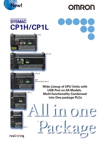
  • 1. Note: Do not use this document to operate the Unit. Authorized Distributor: In the interest of product improvement, specifications are subject to change without notice. Cat. No. P057-E1-06 Printed in Japan 0709 (0507) OMRON Corporation Industrial Automation Company Regional Headquarters OMRON EUROPE B.V. Wegalaan 67-69-2132 JD Hoofddorp The Netherlands Tel: (31)2356-81-300/Fax: (31)2356-81-388 OMRON ELECTRONICS LLC One Commerce Drive Schaumburg, IL 60173-5302 U.S.A. Tel: (1) 847-843-7900/Fax: (1) 847-843-7787 OMRON ASIA PACIFIC PTE. LTD. No. 438A Alexandra Road # 05-05/08 (Lobby 2), Alexandra Technopark, Singapore 119967 Tel: (65) 6835-3011/Fax: (65) 6835-2711 OMRON (CHINA) CO., LTD. Room 2211, Bank of China Tower, 200 Yin Cheng Zhong Road, PuDong New Area, Shanghai, 200120, China Tel: (86) 21-5037-2222/Fax: (86) 21-5037-2200 OMRON Industrial Automation Global: www.ia.omron.com Control Devices Division H.Q. Automation & Drive Division Automation Department 1 Shiokoji Horikawa, Shimogyo-ku, Kyoto, 600-8530 Japan Tel: (81) 75-344-7084/Fax: (81) 75-344-7149 © OMRON Corporation 2009 All Rights Reserved. Wide Lineup of CPU Units with USB Port on All Models. Multi-functionality Condensed into One-package PLCs CP1L-L CP1H CP1L-M CP1L-M CP1L-L Ethernet Option Board CP1H/CP1L
  • 2. A general-purpose USB cable keeps costs low, including the cable cost. Attach an LCD Option Board to the CPU Unit to easily monitor or change data values in the PLC to visually check error status. The Ultimate High-performance Package-type PLC Three types of CPU Unit are available to meet applications requiring advanced functionality: •The CP1H-X with pulse outputs for 4 axes. •The CP1H-Y with 1-MHz pulse I/O. •The CP1H-XA with built-in analog I/O. CP1H CP1L Programmable Terminal Counter Pulse output 3G3MX or other Inverter A Standard Package-type PLC Complete with a standard-feature USB port, CP1L CPU Units are available for applications with as few as 10 I/O points. Whether you need simple sequence control or pulse I/O and a serial port, the CP1L PLCs give you an economical choice from among 10-, 14-, 20-, 30-, 40-, and 60-point CPU Units. Servomotor or Servo Driver Rotary Encoder RS-232CRS-485 Example: SMARTSTEP 2 CP1W-DAM01 LCD Option Board The Board can be used only in the option board slot 1. 32 All-in-one Package PLCs with Condensed Multi-functionality. A Wide Variety of Built-in Functions Expand Application Capabilities and Shorten the Design Time Required for the Growing Number and Increasing Complexity of Ladder Programs Complete Pulse and Serial Functions for Servo and Inverter Applications and Applications Using Programmable Terminals For positioning or communications, simply enter the set values for the instructions. Even complicated functions can be easily programmed using the OMRON Function Block (FB) Library. USB Port Standard on all Models Easy Maintenance and Startup Adjustments with LCD Displays and Settings Building-block PLCsBuilding-block PLCs SYSMAC CJ Series SYSMAC CP Series SYSMAC CS Series No Backplane Backplane Construction I/O Capacity, Program Capacity, Speed Small-scale Control Large-scale System Control From small-scale to large-scale control, programs can be created incorporating function blocks (FB) and structured text (ST) using the same instructions and with the same easy operation. (BOOL) EN (INT) NodeNo (BOOL) Execute (REAL) Velocity (INT) Direction (WORD) AreaID (INT) AreaNo (BOOL) ENO (BOOL) InVelocity (BOOL) CommandAborted (BOOL) Error (WORD) ErrorID _INV032_MoveVelocityHz Speed coincidence Abort Error Error code Always ON Inverter No. Execute Frequency Rotation direction Area Area No. Pulse outputs CP1H/CP1L Note: For details on the R7D-B Series, refer to page 64. Inverter RS-485 (BOOL) EN (INT) Axis (BOOL) Execute (REAL) Position (REAL) Velocity (REAL) Acceleration (REAL) Deceleration (INT) OutPulseSelect (BOOL) ENO (BOOL) Done (BOOL) Busy (BOOL) Error (WORD) ErrorID _INCCP1H010_MoveAbsolute_REAL End positioning Busy Flag Error Flag Error code (Can be omitted.) Always ON (P_On) Axis No. Execute Position command Speed command Acceleration rate Deceleration rate Pulse output method OMRON Function Block for 3G3RV or 3G3MV RS-485 Communications OMRON Function Block for Pulse Output Positioning Servo Driver Example: SMARTSTEP 2, R7D Series, etc. Inverter CP-series Lineup................... Expandability Applications......................... CPU Units............................. Expansion Units................. Functions............................. Pulse Outputs....................... High-speed Counters................. Inverter Positioning................... Serial Communications....... Ethernet Communications... Analog I/O............................. USB Peripheral Port............. LCD Displays and Settings... Support Software............... CPU Unit Functions............ Connecting Expansion Unit and Expansion I/O Units....... CPU Unit Specifications..... Option Unit Specifications... Expansion I/O Unit Specifications..................... Expansion Unit Specifications..................... Dimensions......................... Instructions......................... Ordering Information......... OMRON Function Block Library................................. SMARTSTEP 2 AC Servo Drivers with Pulse String Inputs............. 4 6 8 10 12 12 14 15 16 18 19 20 21 22 24 26 28 43 44 46 48 51 55 62 64 Package PLCsPackage PLCs FA Integrated Tool Package Cannot be used for the CP1L-L10.
  • 3. CP1L-L14D - CP1L-L20D - High-speed Positioning Built-in Analog I/O A Choice of Three Types of CP1H CPU Unit Lets You Select the Functions You Need. Two axes at 1 MHz and two axes at 100 kHz Four axes at 100 kHz Four analog inputs and two analog outputs Four axes at 100 kHz for single-phase (50 kHz for differential phases) RS-232C Option Board LCD Option Board RS-422A/485 Option Board CP1H-Y CPU Units CP1H-XA CPU Units StandardType CP1H-X CPU Units Pulse Outputs for 4 Axes High-speed Counters for 4 Axes Built-in Analog I/O Serial Communications CP-series Lineup A program capacity of 20K steps and 0.1 μs high-speed processing provide multi-axis, high-speed positioning control or analog control. CJ-series Special I/O Units and CPU Bus Units can also be used. Basic package PLCs with serious functions from simple sequence control to 2-axis positioning control. Two axes at 1 MHz for single-phase (500 kHz for differential phases) and two axes at 100 kHz for single-phase (50 kHz for differential phases) Up to two Option Boards can be mounted. CP1H- 40D - CP1L-M30D - CP1L-L10D - CP1L-M40D - CP1L-M60D - 90 mm 86 mm 85 mm 90 mm 66 mm 85 mm 90 mm 86 mm 85 mm 130 mm 85 mm 90 mm 85 mm 90 mm 150mm 85 mm 90 mm 195 mm Program capacity Processing speed I/O capacity LCD Display Settings One LCD Option Board can be mounted in option board slot 1. Ethernet Option Board Ethernet Communications One Ethernet Option Board can be mounted in an option board slot. 54 A Wide Range of CPU Units Allows You to Select the Ideal Model. 10 points 14 points 20 points Pulse Outputs Four-axis control is a standard feature. USB Peripheral Port Another standard feature. LCD Displays and Settings Enabled using Option Board. Ethernet Communications Enabled by using an Option Board. Serial Communications Two ports. Select Option Boards for either RS-232C or RS-485 communications. Built-in Analog I/O XA CPU Units provide 4 input words and 2 output words. Counters Four-axis differential-phase control is a standard feature. Serial Communications Two ports (See note.). Select Option Boards for either RS-232C or RS-485 communications. LCD Displays and Settings Enabled using Option Board. (See note.) Counters with 2-axis differential- phase control are standard features. Single-phase: 4 axes at 100 kHz Note: CP1L-L CPU Units with 14 and 20 points support only one port. Cannot be used for the CP1L-L10. Note: Cannot be used for the CP1L-L10. Note: Cannot be used for the CP1L-L10. 85 mm CP1H Series CP1L Series Program capacity 20K steps Processing speed 0.1 μs (basic instructions) Program capacity 10K steps Processing speed 0.55 μs (basic instructions) Program capacity 5K steps Processing speed 0.55 μs (basic instructions) 90 mm 150 mm 30 points 40 points 60 points Pulse Outputs Two-axis control at 100 kHz is a standard feature. USB Peripheral Port Another standard feature. Ethernet Communications Enabled by using an Option Board.
  • 4. Using Only CP1W Units with the CP1H CP1W/CPM1A Expansion Units and Expansion I/O Units and CJ Units can be used simultaneously. CP1W-CN811 I/O Connecting Cable is required. Note: Some Expansion Units and Expansion I/O Units have certain restrictions on use. (For details, refer to page 24.) Up to 7 CP1W/CPM1A Expansion Units and Expansion I/O Units can be connected. CP1H Application Examples CP1L-M30D - /CP1L-M40D - /CP1L-M60D - CP1L-L14D - /CP1L-L20D - Capacitor picking Process depth Process positioning Rotation (final positioning) Forming Machine Electronic Parts Assembly Machine Spinning Machine Packing Machine Air Cleaner Control Shopping Mall Fountain Control Four-axis, 1-MHz High-speed Pulse Outputs Built-in Analog I/O: 4 Analog Inputs and 2 Analog Outputs 4-axis, 1-MHz High-speed Counters CP1H-XA CPU Unit Temperature Sensor Unit 4 analog inputs and 2 analog outputs Hydraulic pressure control High-speed counters Thread winding speed and length control Cleaner fan motor control (Inverter) Pulse outputs Positioning control via Servomotors CJ Unit Adaptor CP1W-EXT01 CP1H-Y CPU Unit Pulse outputs Sheet feeding control via Servomotors CP1L CP1L CP1LAnalog Output Unit Using CJ-series Special I/O Units, CJ-series CPU Bus Units, and CP1W Units with the CP1H Up to 7 CP1W/CPM1A Expansion Units and Expansion I/O Units can be connected. Up to two CJ-series CPU Bus Units or Special I/O Units can be connected. Up to three CP1W/CPM1A Expansion Units and Expansion I/O Units can be connected. One CP1W/CPM1A Expansion Unit or Expansion I/O Unit can be connected. CP1L Application Examples CP1H/CP1L Communications Interface Options CP1H-Y CPU Unit 76 Expansion Units Provide for a Wider Range of Applications. Two Optional Serial Ports Two Optional Ethernet Ports Option Boards RS-232C Interface CP1W-ClF01 CP1H/CP1L Standard Feature: USB peripheral port Note: Only one board is supported by CP1L-L CPU Units (14 or 20 points). Cannot be used for the CP1L-L10. RS-422A/485 Interface CP1W-ClF11 RS-422A/485 (Isolated-type) Interface CP1W-ClF12 Ethernet Interface CP1W-CIF41 Two types of communications are available. Only one Ethernet port can be used. Either two RS-232C ports or two RS-422A/485 ports can be used. Expandability Applications Two-axis Pulse Outputs Sequence Control Sequence Control with Clock Function Note: Cannot be used for the CP1L-L10.
  • 5. LCD Two serial ports can be added as options (either RS-232C or RS-422A/485 Option Boards). One Ethernet port can be added as an option. 98 CP1H CP1L CP1L-L10DR-A AC power supply, 6 DC inputs, 4 relay outputs CP1L-L10DT-A AC power supply, 6 DC inputs, 4 transistor (sinking) outputs CP1L-L10DR-D DC power supply, 6 DC inputs, 4 relay outputs CP1L-L10DT-D DC power supply, 6 DC inputs, 4 transistor (sinking) outputs CP1L-L10DT1-D DC power supply, 6 DC inputs, 4 transistor (sourcing) outputs CP1L-M60DR-A AC power supply, 36 DC inputs, 24 relay outputs CP1L-M60DT-A AC power supply, 36 DC inputs, 24 transistor (sinking) outputs CP1L-M60DR-D DC power supply, 36 DC inputs, 24 relay outputs CP1L-M60DT-D DC power supply, 36 DC inputs, 24 transistor (sinking) outputs CP1L-M60DT1-D DC power supply, 36 DC inputs, 24 transistor (sourcing) outputs CPU Units Maximize Efficiency by Selecting the Optimum CPU Unit for Your Applications. Pulse outputs (only for transistor outputs) Counters Serial communications Ethernet communications USB peripheral port Built-in analog I/O Memory Cassette LCD display settings Function blocks (ladder diagrams or ST language) Inverter positioning 7-segment display Program capacity Data memory capacity High-speed processing Y CPU Units XA CPU Units X CPU Units M Type 60 Points CP1H-Y20DT-D DC power supply, 12 DC inputs, 8 transistor (sinking) outputs Two line-driver inputs Two line-driver outputs CP1H-XA40DR-A AC power supply, 24 DC inputs, 16 relay outputs, 4 analog inputs, 2 analog outputs CP1H-XA40DT-D DC power supply, 24 DC inputs, 16 transistor (sinking) outputs, 4 analog inputs, 2 analog outputs CP1H-XA40DT1-D DC power supply, 24 DC inputs, 16 transistor (sourcing) outputs, 4 analog inputs, 2 analog outputs CP1H-X40DR-A AC power supply, 24 DC inputs, 16 relay outputs CP1H-X40DT-D DC power supply, 24 DC inputs, 16 transistor (sinking) outputs CP1H-X40DT1-D DC power supply, 24 DC inputs, 16 transistor (sourcing) outputs CP1L-M40DR-A AC power supply, 24 DC inputs, 16 relay outputs CP1L-M40DT-A AC power supply, 24 DC inputs, 16 transistor (sinking) outputs CP1L-M40DR-D DC power supply, 24 DC inputs, 16 relay outputs CP1L-M40DT-D DC power supply, 24 DC inputs, 16 transistor (sinking) outputs CP1L-M40DT1-D DC power supply, 24 DC inputs, 16 transistor (sourcing) outputs CP1L-M30DR-A DC power supply, 18 DC inputs, 12 relay outputs CP1L-M30DT-A AC power supply, 18 DC inputs, 12 transistor (sinking) outputs CP1L-M30DR-D DC power supply, 18 DC inputs, 12 relay outputs CP1L-M30DT-D DC power supply, 18 DC inputs, 12 transistor (sinking) outputs CP1L-M30DT1-D DC power supply, 18 DC inputs, 12 transistor (sourcing) outputs CP1L-L20DR-A AC power supply, 12 DC inputs, 8 relay outputs CP1L-L20DT-A AC power supply, 12 DC inputs, 8 transistor (sinking) outputs CP1L-L20DR-D DC power supply, 12 DC inputs, 8 relay outputs CP1L-L20DT-D DC power supply, 12 DC inputs, 8 transistor (sinking) outputs CP1L-L20DT1-D DC power supply, 12 DC inputs, 8 transistor (sourcing) outputs 100 KHz for four axes 100 kHz (single-phase), 50 kHz (differential phases) 1 MHz (single-phase), 500 kHz (differential phases) for two axes (line driver outputs), 100 kHz (single- phase), 50 kHz (differential phases) for two axes (four axes total) 1 MHz for two axes (line driver outputs), 100 kHz for two axes (four axes total) 100 kHz for two axes 100 kHz (single-phase) for four axes, or 50 kHZ (differential phases) for two axes Two optional serial ports can be added (either RS-232C or RS-422A/485 Option Boards). One Ethernet port can be added as an option. One Ethernet port can be added as an option. One optional serial port can be added (either an RS-232C or RS-422A/485 Option Board). 5K steps 10K words Yes Yes Yes Yes Yes Yes Yes Yes Yes Yes Yes Yes Yes Yes Yes Yes Yes Yes Yes Yes Yes Yes Yes Yes Yes Yes An LCD Option Board can be added as an option to option board slot 1. YesYes Yes Yes Yes Yes Yes Yes Yes Yes 10K steps 32K words 0.55 μs/LD instruction, 1.84 μs/MOV instruction 20K steps 32K words 0.1 μs/LD instruction, 0.3 μs/MOV instruction 4 analog inputs and 2 analog outputs (resolution: 6,000 or 12,000) M Type 40 Points M Type 30 Points L Type 20 Points L Type 14 Points L Type 10 Points CP1L-L14DR-A AC power supply, 8 DC inputs, 6 relay outputs CP1L-L14DT-A AC power supply, 8 DC inputs, 6 transistor (sinking) outputs CP1L-L14DR-D DC power supply, 8 DC inputs, 6 relay outputs CP1L-L14DT-D DC power supply, 8 DC inputs, 6 transistor (sinking) outputs CP1L-L14DT1-D DC power supply, 8 DC inputs, 6 transistor (sourcing) outputs An LCD Option Board can be added as an option to option board slot 1. An LCD Option Board can be added as an option to option board slot 1.
  • 6. Expansion Units CP1W-20EDR1 •12 DC inputs •8 relay outputs CP1W-16ER •16 relay outputs CP1W-20EDT •12 DC inputs •8 transistor outputs (sinking) CP1W-20EDT1 •12 DC inputs •8 transistor outputs (sourcing) CP1W-40EDR •24 DC inputs •16 relay outputs CP1W-40EDT •24 DC inputs •16 transistor outputs (sinking) CP1W-40EDT1 •24 DC inputs •16 transistor outputs (sourcing) CP1W-8ED •8 DC inputs CP1W-8ER •8 relay outputs CP1W-8ET •8 transistor outputs (sinking) CP1W-8ET1 •8 Transistor outputs (sourcing) CompoBus/S I/O Link Unit CP1W-SRT21 •Inputs: 8 •Outputs: 8 CP1W-CN811 I/O Connecting Cable: 80 cm Note: CP1W/CPM1A Expansion Units include I/O Connection Cables (in lengths of approx. 6 cm) for side-by-side connection. 10 11 Options Option Boards CP1H and CP1L CP1H Only I/O Connecting Cable Up to two CJ-series Special I/O Units or CPU Bus Units can be connected by using a CJ Unit Adaptor. Refer to page 27 for the Units that can be used. For details on CJ-series Units, refer to the CJ1 Catalog (Cat. No. P052). RS-232C Option Board CP1W-ClF01 RS-422A/485 Option Board CP1W-ClF11 Memory Cassette CP1W-ME05M CJ Unit Adaptor CP1W-EXT01 (with End Cover) Position Control Units CJ1W-NC 3 (1 to 4 axes) Position Control Unit with MECHATROLINK-II Communications CJ1W-NC271 (2 axes) CJ1W-NC471 (4 axes) CJ1W-NCF71 (16 axes) CJ1W-NCF71-MA (16 axes) Motion Control Unit with MECHATROLINK-II Communications CJ1W-MCH71 (30 axes) SYSMAC SPU High-speed Data Collection Unit CJ1W-SPU01-V2 Controller Link Unit CJ1W-CLK23 FL-Net Unit CJ1W-FLN22 (100Base-TX) DeviceNet Unit CJ1W-DRM21 EtherNet/IP Unit CJ1W-EIP21 Ethernet Unit CJ1W-ETN21 (100Base-TX) Serial Communications Units CJ1W-SCU41-V1 (RS-232C and RS-422/485 ports) CJ1W-SCU21-V1 (Two RS-232C ports) CJ1W-SCU31-V1 (Two RS-422/485 ports) High-speed Counter Unit CJ1W-CT021 (2 axes) ID Sensor Units CJ1W-V680C1 CJ1W-V600C1 (1 or 2 Heads) CompoBus/S Master Unit CJ1W-SRM21 Analog Output Units CJ1W-DA021/041 CJ1W-DA08V/08C (2, 4, or 8 points) Analog Input Units CJ1W-AD041-V1 CJ1W-AD081-V1 (4 or 8 points) Analog I/O Unit CJ1W-MAD42 (4 analog inputs, 2 analog outputs) Process Input Units CJ1W-PH41U CJ1W-AD04U CJ1W-PTS51/52 CJ1W-PTS15/16 CJ1W-PDC15 Temperature Control Units CJ1W-TC (4 or 2 loops) Temperature Sensor Unit CJ-series Special I/O Units and CPU Bus Units CPM1A Expansion Unit and Expansion I/O Units CompoBus/S I/O Link Unit Expansion I/O Units Analog Units Temperature Sensor Unit CP1W-TS001 •Thermocouple inputs: 2 CP1W-TS002 •Thermocouple inputs: 4 Temperature Sensor Unit CP1W-TS101 •Platinum-resistance thermometer inputs: 2 CP1W-TS102 •Platinum-resistance thermometer inputs: 4 CPM1A Expansion Unit and Expansion I/O Units can be used with CP1H or CP1L CPU Units under the same conditions as for the CP1W. Special I/O Units CPU Bus Units Analog Input Unit CP1W-AD041 •Analog inputs: 4 (resolution: 6,000) Analog Output Unit CP1W-DA041 •Analog outputs: 4 (resolution: 6,000) Analog I/O Unit CP1W-MAD11 •Analog inputs: 2 (resolution: 6,000) •Analog outputs: 1 (resolution: 6,000) Analog Input Units CJ1W-ADG41 (4 points) CompoNet Master Unit CJ1W-CRM21 CP1W-32ER •32 relay outputs CP1W-32ET •32 transistor outputs (sinking) CP1W-32ET1 •32 transistor outputs (sourcing) CP1W-16ET •16 transistor outputs (sinking) CP1W-16ET1 •16 transistor outputs (sourcing) LCD Option Board CP1W-DAM01 Ethernet Option Board CP1W-CIF41 RS-422A/485 (Isolated-type) Option Board CP1W-ClF12 CP1W-series and CJ-series Units Can Be Use d for Maximum Expandability
  • 7. Example: Four-axis Control in Electronic Component Manufacturing Equipment Up to Four Axes Are Standard. Advanced Power for High-precision Positioning Control. Positioning for Electronic Component Manufacturing Equipment Pulse Outputs Pulse Output Function for Up to Four Axes. Along with greater precision and more flexibility in multi-product manufacturing, high-speed multi-axis pulse output control responds to the increase in servo applications. Capacitor removal Processing depth Processing positioning Rotation (final positioning) A Full Range of Functions Programming Is Made Easy Using OMRON Function Blocks Applicable CPU Units and Functions Positioning with Trapezoidal Acceleration and Deceleration (PLS2 Instruction) Origin Search Function (ORG Instruction) Stop after output of set number of pulses PLS2 executed Speed control (ACC instruction) Feed Control for Packing Material Target speed control Specified number of travel pulses Acceleration Start frequency Deceleration S-curve acceleration S-curve deceleration Easily achieved with special positioning instruction (PLS2). S-curve acceleration/ deceleration can be used to reduce vibration in high-speed positioning. The packing material is fed and stopped at a fixed position after the seal mark is detected. Origin searches are possible with a single ORG instruction. 12 13 CP1H Servo Drivers Pulse outputs Servomotors 1 MHz for 2 axes and 100 kHz for 2 axes, for a total of 4 axes 100 kHz for 4 axes CP1H-X CPU Unit 100 kHz for 2 axes CP1L CPU UnitCP1H-Y CPU Unit Servo Driver CW/CCWPulse output CP1H/CP1L Just use the CX-Programmer to paste function blocks into the ladder program. Example: Using Positioning OMRON Function Block 1 2 3 Position command 200,000 pulses Acceleration rate 100 Hz/4 ms Deceleration rate 100 Hz/4 ms Speed: 50,000 Hz CW Position command 200,000 pulses Acceleration rate 100 Hz/4 ms Deceleration rate 100 Hz/4 ms Speed 1,000 Hz/4 ms Speed: 50,000 Hz Interrupt input signal 00 (Input word 0, bit 00) SMARTSTEP 2, R7D Series, Etc. Always ON (P-On) Start trigger Bit A Always ON (P-On) Start trigger Bit A Bit A Bit A Bit DBit B Bit DBit B End positioning Bit B Busy Flag Bit C Error Flag Bit D Error code (Can be omitted.) -NCCP1H010-MoveAbsolute-REAL (BOOL) EN (INT) Axis (BOOL) Execute (REAL) Position (REAL) Velocity (REAL) Acceleration (REAL) Deceleration (INT) OutPulseSelect (BOOL) ENO (BOOL) Done (BOOL) Busy (BOOL) Error (WORD) ErrorID Axis No. Pulse output 0: &0 Start Bit A Position command 200,000 pulses: +200,000.0 Speed command 50,000 Hz: +50,000.0 Acceleration rate 100 Hz/4 ms: +100.0 Deceleration rate 100 Hz/4 ms: +100.0 Pulse output method CW/CCW: &0 Axis No. Pulse output 0: &0 Start Bit A Interrupt input selection 0.00 Interrupt position D0 Interrupt feeding amount 200,000 pulses: +200,000.0 Speed command -1 5,000 Hz: +5,000.0 Speed command - 2 1,000 Hz: +1,000.0 Acceleration rate 100 Hz/4 ms: +100.0 Deceleration rate 100 Hz/4 ms: +100.0 Pulse output method CW/CCW method: &0 End positioning Bit B Operating status D10 Processing Flag Bit C Error Flag Contact D Error Flag (Can be omitted.) -NCCP1H110-MoveInterrupt-REAL (BOOL) EN (INT) Axis (BOOL) Execute (BOOL) InterruptSelect (DINT) InterruptPosition (REAL) Distance (REAL) Velocity-1 (REAL) Velocity-2 (REAL) Acceleration (REAL) Deceleration (INT) OutPulseSelect (BOOL) ENO (BOOL) Done (INT) Status (BOOL) Busy (BOOL) Error (WORD) ErrorID Reads High-speed Counter PV. #0000 #0000 DO PRV(881) Always ON (P-On) Interrupt Task 140 Interrupt input 0 (0.00) Rightmost word of output destination Control data Port designation Pulse Outputs Sheet Feeding for Vertical Pillow Packer Interrupt Feeding (ACC and PLS2 Instructions) Just insert set values into the OMRON Function Block. Start the CX-Programmer and right-click "Function Block" in the tree to select the required library file. Use a function block call to select the desired OMRON Function Block. An instance of the function block will be created in the ladder program. Using Interrupt Feeding OMRON Function Block A positioning OMRON Function Block for the CP1H is used in the above application example.The positioning OMRON Function Blocks for the CP1L are the same as the positioning OMRON Function Blocks for the CJ1M-CPU21/22/23. Note: For a list of function blocks in the OMRON Function Block Library, refer to page 62.
  • 8. Inverter speed Inverter speed (command sent via RS-485) Run/stop command Low speed command Inverter Positioning High-speed Counters Differential Phases for Up to Four Axes Are Standard. Easily Handles Multi-axis Control with a Single Unit. High-speed Counters 14 15 High-speed Positioning Operations Using Inverters Is Made Easy. Inverter Positioning The deceleration position must be calculated from the stop position and the speed. Operation is simplified, with no need to calculate the deceleration position! To avoid position error, positioning must be stopped from a low speed. Positioning becomes unreliable if stopped from a high speed. CP1L CPU Unit High-speed counter High-speed counter Calculations are made in the ladder program based on high-speed counter values. Positioning command1 1 2 3 Ladder programError counter Even without going to low speed, positioning is accurate! With no need for low speed, positioning is faster! Overview of Inverter Positioning The CP1L's built-in error counter function enables the following operation. Positioning commands are executed by means of pulse output instructions. Pulse output instructions normally output pulses from the PLC, but pulses can be output to the error counter according to the operand setting in the instruction (such as PLS2). 2 The amount of pulses input to the error counter is converted to a speed command and output to the inverter. A command to the inverter is created in the ladder program using this speed command (proportional to the pulses remaining in the error counter). When RS-485 communications are executed, ladder programming for communicating with the inverter is created. When analog outputs are executed, ladder programming for analog outputs is created. 3 When a run/stop command is executed for the inverter, the motor is rotated and feedback pulses (for the amount of movement) are output from the encoder to the CP1L.The error counter value is decremented by these feedback pulses.The CP1L continues sending commands to the inverter until positioning is completed.This enables accurate positioning to the position output by the first position command. Rotary encoder General- purpose motor Rotary encoder General- purpose motor Rotary encoder General- purpose motor Inverter Inverter Inverter I/O RS-485/analog output Feedback pulses Example: Machinery Such As Ceramics Conveyor Equipment RS-485 Inverters Example: Main-axis Control for Equipment Such as Spinning Machines CP1H CPU Unit High-speed counters RS-485 Applicable CPU Units and Functions CP1H-X CPU Unit CP1L CPU UnitCP1H-Y CPU Unit Applicable CPU Units and Functions Inverter positioning function for two axes CP1L CPU Unit CP1L Previously Now Main-axis Control for Equipment Such as Textile Machinery or Spinning Machinery Machinery Such As Ceramics Conveyor Equipment Positioning Conveyance for Equipment Such as Building Material Manufacturing Machinery and Stone-cutting Machinery Four-axis Counter Function (Single-phase or Differential Phases) Multi-axis counter inputs enable calculations for inverter positioning, spindle speed control in textile manufacturing, and much more. 1 MHz (single-phase), 500 kHz (differential phases) for two axes, 100 kHz (single-phase), 50 kHz (differential phases) for two axes (four axes total) 100 kHz (single-phase), 50 kHz (differential phases) for four axes 100 kHz (single-phase) for four axes, or 50 kHZ (differential phases) for two axes
  • 9. Applicable CPU Units and Functions A Standard USB Port and Two Serial Ports Enable Connecti ons and Communications with a Wide Range of Components. Serial Communications 16 17 Up to two Option Boards can be mounted for RS-232C or RS-422A/485 communications. A peripheral USB port has been added to connect to a personal computer for a total of three communications ports, making it easy to simultaneously connect to a PT, various components (such as Inverters, Temperature Controllers, and Smart Sensors), Serial PLC Link for linking to other PLCs, and a personal computer. CP1H/CP1L CPU Unit CP1H/CP1L CPU Unit (except CP1L-L10) CP1H/CP1L CPU Unit CP1H/CP1L CPU Unit Devices such as OMRON Temperature Controllers with CompoWay/F NS-series PT Personal computer NV-series PT USB cable Modbus-RTU Easy Master Serial PLC Links Smart FB Library CP1H/CP1L CPU Unit CP1H/CP1L CPU Unit Port 1: D32200 to D32249 Port 2: D32300 to D32349 Port 1: D32250 to D32299 Port 2: D32350 to D32399 Slave address (00 to F7 hex) Function code Number of bytes Data transfer Inverter (e.g., 3G3MX) Data (94 bytes max.) Command Slave address Function code Error code Number of bytes Response Data (93 bytes max.) AR Area bits ON/OFF When multiple boilers are being controlled, up to 10 words/Unit of data for settings and monitoring can be exchanged using data links between up to nine CP1H, CP1L, and CJ1M CPU Units. Serial PLC Links can be used with either serial port 1 or serial port 2. Note: Cannot be used for the CP1L-L10. NS-series PTs can also be incorporated as slaves (1:N NT Link connections) to exchange data using the NT Links with only the master CP1H. Each is treated as one slave node. PT Master Slave NS-AL002 (for NS Series) Slave No. 0 Slave No. 7 The CJ1M can also be connected. Master Slave No. 0 Slave No. 7 Master Slave No. 0 Slave No. 7 Master Slave No. 0 Slave No. 7 Setting/monitoring operation Set temperature/present temperature Errors RS-232C Option Board CP1W-CIF01 Two option board slots can be used for either an RS-232C or RS-422A/485 interface. RS-422A/485 Option Board CP1W-CIF11 (Maximum transmission distance 50m) RS-422A/485(Isolated-type) Option Board CP1W-CIF12 (Maximum transmission distance 500m) Serial Option Board for up to two ports. Serial Option Board for up to two ports. CP1L CPU Unit Serial Option Board for only one port. (60, 40 or 30 Points) (20 or 14 Points)CP1L CPU UnitCP1H CPU Unit Inverter Temperature Controller RS-485 Function Blocks for Standard Programming The OMRON Function Blocks provide function blocks for communicating with Inverters and Temperature Controllers. Serial Communications Serial PLC Links Response (BOOL) EN (INT) NodeNo (BOOL) Execute (REAL) Velocity (INT) Direction (WORD) AreaID (INT) AreaNo (BOOL) ENO (BOOL) InVelocity (BOOL) CommandAborted (BOOL) Error (WORD) ErrorID _INV032_MoveVelocityHz Speed coincidence Always ON Inverter No. Start Frequency Direction Area Area No. Connecting inverter speed control is made simple using the Modbus-RTU Easy Master. When the address, function, and data for a slave device are preset in a fixed memory area (DM Area), a message can be sent or received simply by turning ON an AR Area bit (A640.00 for port 1 or A641.00 for port 2) in the PLC. OMRON Function Blocks are provided for operations such as run/stop, frequency settings, and monitoring when connected to Inverters by serial communications, and for setting SPs and reading PVs forTemperature Controllers. Modbus-RTU Easy Master Easy Communications Programming Using OMRON Function Blocks Abort Error Error code Note: Check the version of the inverter serial connection OMRON Function Block Library that can be used with the CP1L and CP1H on page 62 before using the OMRON Function Block Library.
  • 10. Two CPM1A-MAD11 Analog I/O Units (2 Analog Inputs and 1 Analog Output) Two analog output words Previously CP1H 18 19 Four Input Words and Two Output Words for XA CPU Units. Analog Control and Monitoring with Only a Single CPU Unit Analog I/O One port can be used as an Ethernet port to perform Ethernet communications between the CP1H/CP1L and a host computer. Ethernet Communications Oil Pressure Control Oil pressure control can also be handled by this CPU Unit. Complete with CP1W/CPM1A Analog Units. Flow control value Hydraulic actuator Hydraulic pump Pressure control valve Displacement sensors 1/6,000 or 1/12,000 resolution Inspection for warping and twisting Pressure Position Control valves Analog I/O CPM2A CPU Unit CP1H-XA Up to 4 input words and 2 output words. No Expansion Units required. Applicable CPU Units and Functions Four analog input words CP1H-XA CPU Unit Unit with 4 Analog Inputs Units with 4 Analog Outputs Units with 2 Analog Inputs and 1 Analog Output Analog I/O Ethernet Communications Analog Control without Using Expansion Units Four analog inputs and two analog outputs are built in. CP1H-XA CPU Units handle a wide range of applications with a single PLC. Inspection Devices Inspection devices are required more and more to enhance quality. Surface Inspections Using Inspection Devices Mechanisms to Prevent Careless Mistakes in Cell Production (Such as Forgetting to Tighten Screws) Oil Pressure Control in Forming Machines CP1H/CP1L CP1L PLC CP1L CPU Unit (60, 40, or 30 Points) CP1L CPU Unit (20 or 14 Points) CP1H CPU Unit CX-One or other software Ethernet Option Board CP1W-CIF14 Connect to a general-purpose LAN simply by mounting a CP1W-CIF41 Ethernet Option Board to an option board slot on any of the CPU Units in the CP1H/CP1L except a CP1L-L10. Perform monitoring and programming with the CX-Programmer, or communicate between a host computer and the CP1H/CP1L using Ethernet by connecting with the FINS/TCP or FINS/UDP protocols, which are supported by all OMRON PLCs. Computer FINS-UDP FINS-TCP protocol Industrial switching hub W4S1 The Ethernet Option Board can be used in either of the option board slots. (Cannot be used for the CP1L-L10.) Applicable CPU Units and Functions The Ethernet Option Board provides only one port. The Ethernet Option Board provides only one port. The Ethernet Option Board provides only one port. CP1H/CP1L Ethernet Pulse output NS-series Programmable Terminal Example: Food Equipment or Conveyors With Ethernet, you can monitor production for small equipment using a high-speed counter and pulse output.
  • 11. 20 21 LCD Displays and Settings USB Peripheral Port CP1L CP1LCP1H CP1H/CP1L (except CP1L-L10) Compact Display and Setting Device Available to Mount on CPU Unit for Easy Maintenance and Startup Adjustments LCD Displays and Settings Data values in the PLC can be easily monitored or changed by adding the new LCD Option Board. This enables visually checking the operation status, such as error occurrence and error details. Register in advance functions that you use often to quickly perform settings and confirm operation. Functionality can also be expanded to items not included in the CPU Unit, such as calendars and timers. An LCD Option Board interface can be used in option board slot 1. CP1W-DAM01 LCD Option Board Monitoring and Changing Data Values Visual Checking of Status with Display of PLC Error Details Expanded Functionality with Calendar Timers, and Other Items Not Included in the CPU Units Simply press the up and down keys to quickly display up to 16 registered monitor screens. I/O Monitoring All memory area values can be monitored and changed. Switch between decimal and hexadecimal or monitor 2-word hexadecimal data, such as high-speed counter values, in decimal. I/O Monitoring User Monitor Settings and Messages Up to seven fixed characters and the present value of word data can be displayed. Simply press the up and down keys from the initial screen to perform monitoring. Of course, you can also change the settings. Plus, up to 48 characters can be set in advance and then displayed when a specified bit turns ON.This makes onsite setting and confirming faster. The backlight on the LCD screen will turn red when an error occurs to notify you of the error status. You can monitor the displayed error details and the error log. Variety of Additional Functions You can use calendar timers, weekly timers, and daily timers. Sixteen of each timer type can be set. Applicable CPU Units and Functions Can be mounted to option board slot 1. Can be mounted to option board slot 1. Can be mounted to option board slot 1. CPU Units with 30, 40, or 60 I/O points CPU Units with 14 points or 20 I/O points All CP-series CPU Units Provide a USB Port as a Standard Feature. USB Peripheral Port Makes Math Operations Even Easier. The StructuredText (ST) Language High-speed Processing Eight interrupt inputs are built in. Quick-response inputs for pulse widths of 50 μs.The interrupt inputs can also be used as counters. (Response frequency: 5 kHz total for 8 interrupt inputs) The normal inputs can be set in the PLC Setup as interrupt, quick- response, or counter inputs. (There are 8 normal inputs for the CP1H- X/XA, 6 for the CP1H-Y, 6 for the CP1L with 20, 30, or 40 points, and 4 for the CP1L with 14 points.) Processing speed has been increased not only for basic instructions but also for special instructions as well. Faster processing of approximately 500 instructions speeds up the entire system. LD instruction CP1H 0.1 μs 0.3 μs 0.64 μs 7.8 μs 1.72 μs 16.3 μs CPM2A CPM1A MOV instruction CP1L 0.55 μs 4.1 μs Interrupt inputs 8 normal inputs Quick-response inputs Counter inputs In addition to ladder programming, function block logic can be written in ST language, which conforms to IEC 61131-3. Arithmetic processing is also possible with ST, including processing of absolute values, square roots, logarithms, and trigonometric functions (SIN, COS, and TAN). Processing that is difficult to write in ladder programming becomes easy using structured text. The built-in USB port lets you connect to a personal computer using a general-purpose cable. Computer running CX-One Commercially available USB cable FA Integrated Tool Package (The CP1H/CP1L USB port is used only for connecting to a Programming Device.) Note: Programming Consoles (CQM1H-PRO01, C200H-PRO027, etc.) cannot be used with CP1H and CP1L CPU Units. Note:The CP1H/CP1L CPU Units support the same function blocks and ST language as CS/CJ-series CPU Units with unit version 3.0. Commercially available USB cable (A-type male connector to B-type female connector) can be used, helping to keep costs down. Up to Eight Interrupt Inputs Can Be Used. Compared with the CPM2A, Basic Instructions Are at Least Six Times Faster and MOV Instructions Are 26 Times Faster. StructuredText Commands (Keywords) TRUE, FALSE. IF,THEN, ELSE, ELSIF, END_IF. DO, WHILE, END_WHILE. REPEAT, UNTIL, END_REPEAT. FOR,TO, BY, DO, END_FOR. CASE, OF, END_CASE. EXIT, RETURN. Operators Addition (+), Subtraction (-), Multiplication (*), Division (/) Parenthesis (brackets), Array Indexing (square brackets [ ] ) Assignment Operator (:=), LessThan Comparison Operator (<), LessThan or EqualTo Comparison Operator (<=), GreaterThan Comparison Operator (>), GreaterThan or EqualTo Comparison Operator (>=), Equals Comparison Operator (=), Is Not EqualTo Comparison Operator (<>), Bitwise AND (AND or &), Bitwise OR (OR), Exclusive OR (XOR), NOT (NOT), Exponentiation (**) Numerical Functions ABS, SQRT, SQRT, LN, LOG, EXP, SIN, COS,TAN, ASIN, ACOS, ATAN, EXPT Arithmetic Functions Exponentiation (EXPT)
  • 12. 22 23 Shortened System Design and Startup. Increased Program Reusability. Support Software Integrated OMRON PLCs and Component Support Software Improved Functional Connectivity with HMI Design Software and Integration of Component Software Temperature Controller FA Integrated Tool Package The CX-One is an FA IntegratedTool Package for connecting, setting, and programming OMRON components, including PLCs. CP1H/CP1L programming and settings can be done with just the CX-Programmer, but the CX-One provides Support Software for setting and programming PTs,Temperature Controllers, and many other components. Using the CX-One makes programming and setup easy, shortening the total lead time required for starting up machines and equipment. CX-One Configuration CX-Process Tool NS-series Face Plate Auto-Builder CX-Thermo CX-Drive CX-Motion-NCF CX-Motion-MCH CX-Position CX-Motion Network Software HMI Software PLC Software CX-Designer Ladder Monitor software included. (See note 1.) NV-Designer (See note 2.) CX-Programmer CX-Simulator SwitchBox Utility CX-Integrator CX-FLnet CX-Protocol CX-ConfiguratorFDT Network Configurator CX-Designer The CX-Designer can be started from the CX- Integrator's NT Link Window. It can be used to design HMI screens. In addition, the Smart Active Parts (SAP) Library is provided with the CX-Designer to enable easily creating setting screens for devices such as Temperature Controllers. Serial (CompoWay/F)Exchanging data with PLC NS-series PT Smart Active Parts (SAP) NT Link Example: The Temperature Controller is visible. Configured with an NS-series PT 1 2 3 Motion Controller Software 4 PLC Software5 Component Software (for Temperature Controllers)(for Temperature Controllers) 6 Note: 1.The Ladder Monitor is required to monitor ladder programs running on CS/CJ-series PLCs from an NS-series PT. 2. Include with CX-One Lite version 4.0 and in CX-One version 3.2 or later. Shortcut keys can be easily checked using the ladder key guide. Programming is simplified by key inputs, such as the Key for an NC input (contact), the Key for an OUT instruction, and the Key for special instructions. Key, address, Key, comment, Key. The CX-Programmer automatically goes into character input mode when it is time to enter a comment. Special instructions can be input as follows: Simple key inputs are also available to connect lines. Comments can be added for timer and counter instructions through timer and counter input bits. CX-Programmer Easy-to-use Programming Software. Programming with Function Blocks (Ladder Diagrams/ST Language) Is Also Standard. Easy Operation Simplifies Programming and Debugging. CP1L except for CPU Units with 60 points: Version 7.2 (CX-One version 2.1) or later CP1L CPU Units with 10 or 60 points: Version 7.3 (CX-One version 2.13) or later CP1H: Version 6.2 (CX-One version 1.1) or later Eight-character Password Protection Password setting: Up to 8 alphanumeric characters (A-Z, a-z, 0-9) The Password Function Enables Protecting Important Programs. Important programs can be protected by setting a password from the CX-Programmer (with the PLC online). MEMO.
  • 13. Front AC100-240V POWER ERR/ALM BKUP 100CH 101CHDC24V0.3A OUTPUT 1CH EXP L1 L2/N COM 01 03 05 07 09 11 01 03 05 07 09 11 00 02 04 06 08 10 00 02 04 06 08 10 00 01 02 03 04 06 00 01 03 04 06 COM COM COM COM 05 07 COM 02 COM 05 07 IN OUT Back Front Back 24 25 Note: CPU Unit Overview and Built-in Functions Analog Inputs Are Made Simple. An analog adjustment and an external analog setting input connector are provided. External Analog Setting Input Connector This connector is used for an 0 to 10-V analog input with a 256 resolution. Each CP1H/CP1L CPU Unit has one of these connectors built in. A device, such as a potentiometer, can be connected to enable direct manual operation and control from a control panel. The maximum cable length is 3 meters. A connecting cable (1 m) is included with the CPU Unit. Analog Adjustment The analog adjustment has a resolution of 256. Values are entered in A642 and can be used in the ladder program. When the value is changed, it is displayed (0 to FF) for three seconds on the 7-segment display. CP1W-ME05M Memory Cassette Shopping Mall Fountain Control Controlling a Fountain for a Period of Time Program Example A If bit A is ON, the fountain pump turns ON from 10:00 AM to 7:30 PM. DT A 100.00 Fountain pump D0 A351 D100 Time: 10:00 AM or later. Time: 7:30 PM or earlier. (Only CP1H CPU Units provide a 7-segment display.) C S1 S2 D0 Compares seconds data. Compares minutes data. Compares hour data. Masks day data. Masks month data. Masks year data. Sets D0 to 0038 hex.– – 1 1 1 0 0 0 7 6 5 4 3 2 1 0 DT D0 A351 D103 C S1 S2 PLC program design Memory Cassette Production site Production site Example display: A memory error occurs in the UM (error code 80F1, error details 0001). System development That's a memory error. Memory Cassette Status Displayed on 7-segment Display (CP1H only) Clock Function CP1L CPU Units (M Type) with 40 Points CP1L CPU Units (L Type) with 20 or 14 Points CP1L CPU Units (L Type) with 10 Points A351 A352 A353 15 8 7 0 Min S Day Hour Year Month S2 : D100 S2+1: D101 S2+2: D102 15 8 7 0 00 00 – 10 – – Compares shaded areas. S2 : D103 S2+1: D104 S2+2: D105 15 8 7 0 30 00 – 19 – – SYSMAC CP1L PERIPHERAL BATTERY L1 L2/N COM 01 03 05 07 09 11 00 02 04 06 08 10 00 01 02 04 05 07 COM COM COM 03 COM 06 IN OUT Battery Cover Operation Indicators Peripheral USB Port Seven-segment LED Display Analog Control External Analog Settings Input Connector DIP Switch Built-in Analog I/O Terminal Block (See note.) Built-in Analog Input Switch (See note.) Memory Cassette Slot Note: XA CPU Units only. Terminal Block (Removable) Terminal Block (Removable) Option Board Slot 2 Option Board Slot 1 Input Indicators Output Indicators Expansion Unit and Expansion I/O Unit Connector CJ Unit Adapter Connector Option Board Slot 2 Option Board Slot 1 Data, such as programs and initial memory values, can be stored on a Memory Cassette (optional) and copied to other systems. The Memory Cassette can also be used when installing new versions of application programs. All CP1H/CP1L CPU Units have a built-in clock. The 7-segment display provides two display digits. In addition to displaying error codes for errors detected by the PLC, codes can be displayed on the display from the ladder program. The 7-segment display is useful for maintenance as well, allowing problems that arise during system operation to be grasped without using any Support Software. Battery-free Operation CP1H CPU Unit Nomenclature CP1L CPU Unit Nomenclature The values in the DM Area (32K words) are saved in the CPU Unit's built-in flash memory as initial values, and can be read at startup. Battery-free operation can be used to enable saving production data and machine parameters in the DM Area, turning OFF the power, and then using then same data again for the next production run. (This is ideal for machinery that is only used seasonally.) • A battery is required for the clock function and to retain the status of HR Area bits and counter values. • A battery is provided as a standard feature with the CPU Unit. • The user program (ladder program) is stored in built-in flash memory, so no battery is required to back it up. 01 03 04 06 COM 05 07 L1 L2/N COM 01 03 05 07 09 11 01 03 05 07 09 11 00 02 04 06 08 10 00 02 04 06 08 10 A{ 00 01 02 03 04 06 00 A| COM COM COM COM 05 07 COM 02 IN OUT Memory Cassette Slot Memory Cassette Slot Memory Cassette Slot Option Board Slot Peripheral USB Port Analog Control External Analog Settings Input Connector DIP Switch Battery Battery Battery Expansion Unit and Expansion I/O Unit Connector Terminal Block (Removable) Terminal Block (Removable) CPU Unit Functions Terminal Block (Fixed) Terminal Block (Fixed) Terminal Block (Fixed) Terminal Block (Fixed)
  • 14. Use CP1W-CN811 I/O Connecting Cable when using CP1W/CPM1A Expansion Units and Expansion I/O Units at the same time as a CJ Unit Adapter. In this situation, the number of CP1W/CPM1A Expansion Unit and Expansion I/O Units that can be connected is subject to the restrictions described above. Only one I/O Connecting Cable can be used. Note: CP1L (L Type) CPU Units with 10 points do not support Expansion Units. Based on the current consumption when CJ-series Special I/O Units or CPU Bus Units are used with a CP1H CPU Unit, the maximum number of Units that can be used is two CJ-series Units and seven CP1W/CPM1A Expansion Units and Expansion I/O Units. The current consumption for the CP1H must be no more than 2 A for 5 V and 1 A for 24 V, and the total current consumption must be no more than 30 W. Check the total current consumption to be sure these limits are not exceeded referring to page 29 for the CP1H CPU Unit and CP1W Expansion Unit and Expansion I/O Unit current consumptions and to the above table for CJ-series Unit current consumptions. Maximum Number of CP1W/CPM1A Expansion Unit and Expansion I/O Units 26 27 Connecting Expansion Unit and Expansion I/O Units Restrictions on the Number of CP1H Expansion Unit and I/O Unit Connections Using CP1W-CN811 I/O Connecting Cable Using CJ-series Special I/O Units or CPU Bus Units with a CP1H CPU Unit CP1H CPU Unit 7 max. (Refer to restrictions below.) 3 max. 1 max. Unit type Expansion I/O Units Analog Units Temperature Sensor Units CompoBus/S I/O Link Unit 40 I/O points 32 outputs 2 analog inputs,1 analog output 4 analog inputs 4 analog outputs 2 thermocouple inputs 4 thermocouple inputs 2 platinum resistance thermometer inputs 4 platinum resistance thermometer inputs 8 inputs and 8 outputs 20 I/O points 2 2 1 1 2 4 1 1 2 1 4 2 4 2 4 2 4 1 1 16 outputs 8 inputs 8 outputs CP1W-40EDR CP1W-40EDT CP1W-40EDT1 CP1W-32ER CP1W-32ET CP1W-32ET1 Model No. of words Input Output Number of Units CP1H-X40DR-A CP1W-TS002 x 3 4 words x 3 Units = 12 words 0 words CP1W -TS001 x 1 2 words x 1 Unit = 2 words 0 words CP1W -20EDR1 x 1 1 word x 1 Unit = 1 word 1 word x 1 Unit = 1 word CP1W - DA041 x 2 0 words 4 words x 2 Units = 8 words Total: 7 Units Total: 15 words Total: 9 words 7 Units 15 words 15 words OutputInput Expansion: 1st Unit 2nd Unit 3rd Unit 4th Unit 5th Unit 6th Unit 7th Unit Can be used. Cannot be used. End CoverCJ Unit Adapter CP1W-EXT01 7 max. Connecting Expansion Unit and Expansion I/O Units Words Allocated to CP1W Expansion Units and Expansion I/O Units For example, the CP1W-TS002 Temperature Sensor Unit is allocated four words per Unit, so no more than three Units can be connected (4 words x 3 Units = 12 words). It would then be possible to mount a combination of other Units to use the remaining three input and 15 output words. Examples of Possible Combinations CP1L (M) CPU Units with 60, 40, or 30 Points CP1L (L) CPU Units with 20 or 14 Points Up to seven Expansion Units and Expansion I/O Units can be connected when a CP1H CPU Unit is used, but the following restrictions apply. Observe these restrictions when using the models in the shaded areas in the following tables. A maximum total of 15 input words is allocated for Expansion Units and a maximum total of 15 output words is allocated for Expansion Units and Expansion I/O Units. • I/O Connecting Cable can be connected to any Unit from the CP1H/CP1L CPU Unit to the third Expansion Unit or Expansion I/O Unit (i.e., the fourth Unit). • Only one I/O Connecting Cable can be used in each CP1H or CP1L PLC. • Even when I/O Connecting Cable is used, the above restrictions on the number of connectable CP1W/CPM1A Expansion Units and Expansion I/O Units still apply. Up to two CJ-series Special I/O Units or CPU Bus Units can be connected by using a CP1W-EXT01 CJ Unit Adapter.The number of Units that can be used is as described below. CJ-series Special I/O Units and CPU Bus Units (For details, refer to the CJ1 Catalog (Cat. No. P052)). Up to two CJ-series Special I/O Units or CPU Bus Units can be connected. * The current consumption increases by 0.15 A/Adapter when NT-AL001 Link Adapters are used, and by 0.04 A/ Converter when CJ1W-CIF11 RS-422A Converters are used. CP1W-20EDR1 CP1W-20EDT CP1W-20EDT1 CP1W-16ER CP1W-16ET CP1W-16ET1 CP1W-8ED CP1W-8ER CP1W-8ET CP1W-8ET1 CP1W-MAD11 CP1W-AD041 CP1W-DA041 CP1W-TS001 CP1W-TS002 CP1W-TS101 CP1W-TS102 CP1W-SRT21 Unit name Model 5 V Current consumption (A) Analog Input Units Analog Output Units Analog I/O Unit Process Input Units Temperature Control Units CompoBus/S Master Unit CJ1W-AD081-V1 0.42 A 0.14 A 0.12 A 0.58 A 0.30 A 0.32 A 0.25 A 0.18 A 0.25 A 0.15 A CJ1W-AD041-V1 CJ1W-DA08V CJ1W-DA08C CJ1W-DA041 CJ1W-DA021 CJ1W-MAD42 CJ1W-PTS51 CJ1W-PTS52 CJ1W-PH41U CJ1W-AD04U CJ1W-PTS15 CJ1W-PTS16 CJ1W-PDC15 CJ1W-TC001 CJ1W-TC002 CJ1W-TC003 CJ1W-TC004 CJ1W-TC101 CJ1W-TC102 CJ1W-TC103 CJ1W-TC104 CJ1W-SRM21 0.40 ACJ1W-CRM21 5 V Current consumption (A) Unit name Model 0.25 A 0.36 A 0.25 A 0.36 A 0.25 A 0.26 A (24 VDC 0.12 A) 0.32 A (24 VDC 0.24 A) 0.38 A* 0.28 A* 0.37 A 0.33 A 0.35 A 0.6 A 0.37 A 0.56 A Position Control Units High-speed Counter Unit ID Sensor Units CJ1W-NC113 CJ1W-NC213 CJ1W-NC413 CJ1W-NC133 CJ1W-NC233 CJ1W-NC433 CJ1W-CT021 CJ1W-V600C11 CJ1W-V600C12 0.26 A (24 VDC 0.13 A) 0.32 A (24 VDC 0.26 A) CJ1W-V680C11 CJ1W-V680C12 Serial Communications Units Ethernet Unit DeviceNet Unit Controller Link Unit MECHATROLINK-II Position Control Unit MECHATROLINK-II Motion Control Unit FL-net Unit Storage/Processing Unit CJ1W-SCU41-V1 CJ1W-SCU21-V1 0.38 ACJ1W-SCU31-V1 CJ1W-ETN21 0.41 AEtherNet/IP Unit CJ1W-EIP21 CJ1W-DRM21 CJ1W-CLK23 CJ1W-NC271 0.36 A CJ1W-NC471 CJ1W-NCF71 CJ1W-NCF71-MA CJ1W-MCH71 CJ1W-FLN22 CJ1W-SPU01-V2 CompoNet Master Unit
  • 15. 28 CPU Unit Specifications ■ I/O Bits and I/O Allocations With CP1H and CP1L CPU Units, the beginning input and output words (CIO 0 and CIO 100) are allocated by the CPU Unit one or two words at a time. I/O bits are allocated in word units in order of connection to Expansion Units and Expansion I/O Units connected to a CPU Unit. Note: For details on the number of words allocated to Expansion Units and Expansion I/O Units, refer to Words Allocated to CP1W Expansion Units and Expansion I/O Units on page 26. ● Example: I/O Bit Allocations When Expansion Units Are Connected CPU Unit with 40 I/O Points + Temperature Sensor Unit + Analog Output Unit + Expansion I/O Unit with 40 I/O Points ■ General Specifications Note: The above values are for a cold start at room temperature for an AC power supply, and for a cold start for a DC power supply. • A thermistor (with low-temperature current suppression characteristics) is used in the inrush current control circuitry for the AC power supply. The thermistor will not be sufficiently cooled if the ambient temperature is high or if a hot start is performed when the power supply has been OFF for only a short time. In those cases the inrush current values may be higher (as much as two times higher) than those shown above. Always allow for this when selecting fuses and breakers for external circuits. • A capacitor charge-type delay circuit is used in the inrush current control circuitry for the DC power supply. The capacitor will not be charged if a hot start is performed when the power supply has been OFF for only a short time, so in those cases the inrush current values may be higher (as much as two times higher) than those shown above. CPU Unit Allocated words Inputs Outputs CP1H CPU Unit with 40 I/O points CIO 0 and CIO 1 CIO 100 and CIO 101 CP1L CPU Unit with 10, 14, or 20 I/O points CIO 0 CIO 100 CP1L CPU Unit with 30 or 40 I/O points CIO 0 and CIO 1 CIO 100 and CIO 101 CP1L CPU Unit with 60 I/O points CIO 0, CIO 1, and CIO 2 CIO 100, CIO 101, and CIO102 Type AC power supply models DC power supply models Item Model CP1H-@@@-A CP1L-@@@-A CP1H-@@@-D CP1L-@@@-D Power supply 100 to 240 VAC 50/60 Hz 24 VDC Operating voltage range 85 264 VAC 20.4 to 26.4 VDC Power consumption 100 VA max. (CP1H-@@@-A) 50 VA max. (CP1L-M60/-M40/-M30@@-A) (See next page.) 30 VA max. (CP1L-L20/-L14/-L10@@-A) 50 W max. (CP1H-@@@-D) 20 W max. (CP1L-M60/-M40/-M30@@-D) (See next page.) 13 W max. (CP1L-L20/-L14/-L10@@-D) Inrush current (See note.) 100 to 120 VAC inputs: 20 A max. (for cold start at room temperature) 8 ms max. 200 to 240 VAC inputs: 40 A max. (for cold start at room temperature), 8 ms max. 30 A max. (for cold start at room temperature) 20 ms max. External power supply 300 mA at 24 VDC (CP1H, CP1L-M60/-M40/-M30@@-A) 200 mA at 24 VDC (CP1L-L20/-L14/-L10@@-A) None Insulation resistance 20 MΩ min. (at 500 VDC) between the external AC terminals and GR terminals No insulation between primary and secondary for DC power supply Dielectric strength 2,300 VAC at 50/60 Hz for 1 min between the external AC and GR terminals, leakage current: 5 mA max. No insulation between primary and secondary for DC power supply Noise immunity Conforms to IEC 61000-4-4. 2 kV (power supply line) Vibration resistance Conforms to JIS C0040. 10 to 57 Hz, 0.075-mm amplitude, 57 to 150 Hz, acceleration: 9.8 m/s2 in X, Y, and Z directions for 80 minutes each. Sweep time: 8 minutes × 10 sweeps = total time of 80 minutes) Shock resistance Conforms to JIS C0041. 147 m/s2 three times each in X, Y, and Z directions Ambient operating tempera- ture 0 to 55°C Ambient humidity 10% to 90% (with no condensation) Ambient operating environ- ment No corrosive gas Ambient storage temperature −20 to 75°C (Excluding battery.) Power holding time 10 ms min. 2 ms min. CPU Unit with 40 I/O Points CP1H-X@40D 1st Unit Temperature Sensor Unit CP1W-TS002 2nd Unit Analog Output Unit CP1W-DA041 3rd Unit Expansion I/O Unit with 40 I/O Points CP1W-40ED CIO 0.00 to CIO 0.11 CIO 1.00 to CIO 1.11 CIO 6.00 to CIO 6.11 CIO 7.00 to CIO 7.11 CIO 100.00 to CIO 100.07 CIO 101.00 to CIO 101.07 CIO 106.00 to CIO 106.07 CIO 107.00 to CIO 107.07 CIO 2 to 5 None None CIO 102 to CIO 105 24 inputs 16 outputs 24 inputs 16 outputs Inputs Outputs
  • 16. 29 CPU Unit Specifications ■ Current Consumption The power consumption shown on page 28 is the maximum power consumption. To obtain the correct power consumption for the system config- uration, calculate the power consumption for the external power supply from the current consumption given below for the CPU Unit, Expansion Units, and Expansion I/O Units. (When using CJ-series Units with the CP1H, add the current consumption for the CJ-series Units shown on page 27.) ● CPU Units Note: 1. The current consumption of the CP1W-ME05M Memory Cassette and the CP1W-CIF01/CIF11 Option Boards are included in the current consumption of the CPU Unit. 2. CPU Units with DC power do not provide an external power supply. 3. The current consumptions given in the following table must be added to the current consumption of the CPU Unit if an Expansion Unit or Expansion I/O Unit is connected. 4. The external power supply cannot be used if an Expansion Unit or Expansion I/O Unit is connected to a CPU Unit with 14 or 20 I/O points. 5. Values in parentheses are the maximum external power supply for a CPU Unit to which an Expansion I/O Unit is not connected. Refer to the CP1L CPU Unit Operation Manual (Cat. No. W462) or CP1H CPU Unit Operation Manual (Cat. No. W450) for details. Model Current consumption External power supply 5 VDC 24 VDC 24 VDC (See note 5.) CP1H-X40DR-A 0.42 A 0.07 A 0.3 A max. (0.9 A max.) CP1H-X40DT-D 0.50 A 0.01 A --- CP1H-X40DT1-D 0.50 A 0.02 A --- CP1H-XA40DR-A 0.43 A 0.18 A 0.3 A max. (0.8 A max.) CP1H-XA40DT-D 0.51 A 0.12 A --- CP1H-XA40DT1-D 0.51 A 0.15 A --- CP1H-Y20DT-D 0.55 A --- --- CP1L-M60DR-A 0.25 A 0.14 A 0.3 A max. (0.5 A max.) CP1L-M60DT-A 0.39 A 0.03 A 0.3 A max. (0.6 A max.) CP1L-M60DR-D 0.25 A 0.14 A --- CP1L-M60DT-D 0.39 A 0.03 A --- CP1L-M60DT1-D 0.39 A 0.03 A --- CP1L-M40DR-A 0.22 A 0.08 A 0.3 A max. (0.6 A max.) CP1L-M40DT-A 0.31 A 0.03 A 0.3 A max. (0.6 A max.) CP1L-M40DR-D 0.22 A 0.08 A --- CP1L-M40DT-D 0.31 A 0.03 A --- CP1L-M40DT1-D 0.31 A 0.03 A --- CP1L-M30DR-A 0.21 A 0.07 A 0.3 A max. (0.6 A max.) CP1L-M30DT-A 0.28 A 0.03 A 0.3 A max. (0.6 A max.) CP1L-M30DR-D 0.21 A 0.07 A --- CP1L-M30DT-D 0.28A 0.03 A --- CP1L-M30DT1-D 0.28 A 0.03 A --- CP1L-L20DR-A 0.20 A 0.05 A 0.2 A max. CP1L-L20DT-A 0.24 A 0.03 A 0.2 A max. CP1L-L20DR-D 0.20A 0.05 A --- CP1L-L20DT-D 0.24 A 0.03 A --- CP1L-L20DT1-D 0.24 A 0.03 A --- CP1L-L14DR-A 0.18 A 0.04 A 0.2 A max. CP1L-L14DT-A 0.21 A 0.03 A 0.2 A max. CP1L-L14DR-D 0.18 A 0.04 A --- CP1L-L14DT-D 0.21 A 0.03 A --- CP1L-L14DT1-D 0.21 A 0.03A --- CP1L-L10DR-A 0.16 A 0.03 A 0.2 A max. CP1L-L10DT-A 0.18 A 0.03 A 0.2 A max. CP1L-L10DR-D 0.16 A 0.03A --- CP1L-L10DT-D 0.18 A 0.03 A --- CP1L-L10DT1-D 0.18 A 0.03 A ---
  • 17. 30 CPU Unit Specifications ● Expansion Units and Expansion I/O Units Unit name Model Current consumption 5 VDC 24 VDC Expansion I/O Units 40 I/O points 24 inputs 16 outputs CP1W-40EDR 0.080 A 0.090 A CP1W-40EDT 0.160 A --- CP1W-40EDT1 32 outputs CP1W-32ER 0.049 A 0.131 A CP1W-32ET 0.113 A --- CP1W-32ET1 20 I/O points 12 inputs 8 outputs CP1W-20EDR1 0.103 A 0.044 A CP1W-20EDT 0.130 A --- CP1W-20EDT1 16 outputs CP1W-16ER 0.042 A 0.090 A CP1W-16ET 0.076 A --- CP1W-16ET1 8 inputs CP1W-8ED 0.018 A --- 8 outputs CP1W-8ER 0.026 A 0.044 A CP1W-8ET 0.075 A --- CP1W-8ET1 Analog Input Unit 4 inputs CP1W-AD041 0.100 A 0.090 A Analog Output Unit 4 outputs CP1W-DA041 0.080 A 0.124 A Analog I/O Unit 2 inputs and 1 output CP1W-MAD11 0.083 A 0.110 A Temperature Sensor Units K or J thermocouple inputs CP1W-TS001 0.040 A 0.059 A CP1W-TS002 Pt or JPt platinum resistance thermometer inputs CP1W-TS101 0.054 A 0.073 A CP1W-TS102 CompoBus/S I/O Link Unit 8 inputs and 8 outputs CP1W-SRT21 0.029 A ---
  • 18. 31 CPU Unit Specifications ■ Characteristics ● CP1H Type CP1H-XA CPU Units CP1H-X CPU Units CP1H-Y CPU Units Item Models CP1H-XA@@@-@ CP1H-X@@@-@ CP1H-Y@@@-@ Control method Stored program method I/O control method Cyclic scan with immediate refreshing Program language Ladder diagram Function blocks Maximum number of function block definitions: 128 Maximum number of instances: 256 Languages usable in function block definitions: Ladder diagrams, structured text (ST) Instruction length 1 to 7 steps per instruction Instructions Approx. 500 (function codes: 3 digits) Instruction execution time Basic instructions: 0.10 μs min. Special instructions: 0.15 μs min. Common processing time 0.7 ms Program capacity 20K steps Number of tasks 288 (32 cyclic tasks and 256 interrupt tasks) Scheduled inter- rupt tasks 1 (interrupt task No. 2, fixed) Input interrupt tasks 8 (interrupt task No. 140 to 147, fixed) 6 (interrupt task No. 140 to 145, fixed) (Interrupt tasks can also be specified and executed for high-speed counter interrupts.) Maximum subroutine number 256 Maximum jump number 256 I/O areas (See note.) Input bits 1,600 bits (100 words): CIO 0.00 to CIO 99.15 (The 24 built-in inputs are allocated in CIO 0.00 to CIO 0.11 and CIO 1.00 to CIO 1.11.) Output bits 1,600 bits (100 words): CIO 100.00 to CIO 199.15 (The 16 built-in outputs are allocated in CIO 100.00 to CIO 100.07 and CIO 101.00 to CIO 101.07.) Built-in Analog Inputs CIO 200 to CIO 203 --- Built-in Analog Outputs CIO 210 to CIO 211 --- Serial PLC Link Area 1,440 bits (90 words): CIO 3100.00 to CIO 3189.15 (CIO 3100 to CIO 3189) Work bits 8,192 bits (512 words): W0.00 to W511.15 (W0 to W511) CIO Area: 37,504 bits (2,344 words): CIO 3800.00 to CIO 6143.15 (CIO 3800 to CIO 6143) TR Area 16 bits: TR0 to TR15 Holding Area 8,192 bits (512 words): H0.00 to H511.15 (H0 to H511) AR Area Read-only (Write-prohibited): 7168 bits (448 words): A0.00 to A447.15 (A0 to A447) Read/Write: 8192 bits (512 words): A448.00 to A959.15 (A448 to A959) Timers 4,096 bits: T0 to T4095 Counters 4,096 bits: C0 to C4095 DM Area 32 Kwords: D0 to D32767 Data Register Area 16 registers (16 bits): DR0 to DR15 Index Register Area 16 registers (32 bits): IR0 to IR15 Task Flag Area 32 flags (32 bits): TK0000 to TK0031 Trace Memory 4,000 words (500 samples for the trace data maximum of 31 bits and 6 words.) Memory Cassette A special Memory Cassette (CP1W-ME05M) can be mounted. Note: Can be used for program backups and auto-booting. Clock function Supported. Accuracy (monthly deviation): −4.5 min to −0.5 min (ambient temperature: 55°C), −2.0 min to +2.0 min (ambient temperature: 25°C), −2.5 min to +1.5 min (ambient temperature: 0°C) Communications functions One built-in peripheral port (USB 1.1): For connecting Support Software only. A maximum of two Serial Communications Option Boards can be mounted. A maximum of one Ethernet Option Board can be mounted. Memory backup Flash memory: User programs, parameters (such as the PLC Setup), comment data, and the entire DM Area can be saved to flash memory as initial values. Battery backup: The Holding Area, DM Area, and counter values (flags, PV) are backed up by a battery. Battery service life 5 years at 25°C. (Use the replacement battery within two years of manufacture.) Built-in input terminals 40 (24 inputs, 16 outputs) 20 (12 inputs, 8 outputs) Line-driver inputs: Two axes for phases A, B, and Z Line-driver outputs: Two axes for CW and CCW Number of connectable Expansion (I/O) Units CP Expansion I/O Units: 7 max.; CJ-series Special I/O Units or CPU Bus Units: 2 max. Max. number of I/O points 320 (40 built in + 40 per Expansion (I/O) Unit × 7 Units) 300 (20 built in + 40 per Expansion (I/O) Unit × 7 Units) Interrupt inputs 8 inputs (Shared by the external interrupt inputs (counter mode) and the quick-response inputs.) 6 inputs (Shared by the external interrupt inputs (counter mode) and the quick-response inputs.) Interrupt input counter mode 8 inputs (Response frequency: 5 kHz max. for all interrupt inputs), 16 bits Up or down counters 6 inputs (Response frequency: 5 kHz max. for all interrupt inputs), 16 bits Up or down counters Quick-response inputs 8 points (Min. input pulse width: 50 μs max.) 6 points (Min. input pulse width: 50 μs max.) Scheduled interrupts 1
  • 19. 32 CPU Unit Specifications Note: The memory areas for CJ-series Special I/O Units and CPU Bus Units are allocated at the same as for the CJ-series. For details, refer to the CJ Series catalog (Cat. No. P052). ● CP1L High-speed counters 4 inputs: Differential phases (4x), 50 kHz or Single-phase (pulse plus direction, up/down, increment), 100 kHz Value range: 32 bits, Linear mode or ring mode Interrupts: Target value comparison or range comparison 2 inputs: Differential phases (4x), 500 kHz or Single-phase, 1 MHz and 2 inputs: Differential phases (4x), 50 kHz or Single-phase (pulse plus direction, up/down, increment), 100 kHz Value range: 32 bits, Linear mode or ring mode Interrupts: Target value comparison or range comparison Pulse outputs (models with transistor out- puts only) Pulse out- puts Trapezoidal or S-curve acceleration and deceleration (Duty ratio: 50% fixed) 4 outputs, 1 Hz to 100 kHz (CCW/CW or pulse plus direction) Trapezoidal or S-curve acceleration and deceleration (Duty ratio: 50% fixed) 2 outputs, 1 Hz to 1 MHz (CCW/CW or pulse plus direction) 2 outputs, 1 Hz to 100 kHz (CCW/CW or pulse plus direction) PWM out- puts Duty ratio: 0.0% to 100.0% (Unit: 0.1%) 2 outputs, 0.1 to 1 kHz (Accuracy: ±5% at 1 kHz) Duty ratio: 0.0% to 100.0% (Unit: 0.1%) 2 outputs, 0.1 to 1 kHz (Accuracy: ±5% at 1 kHz) Built-in analog I/O terminals 4 analog inputs and 2 analog outputs None Analog control 1 (Setting range: 0 to 255) External analog input 1 input (Resolution: 1/256, Input range: 0 to 10 V), not isolated Type CP1L-M60 (60 points) CP1L-M40 (40 points) CP1L-M30 (30 points) CP1L-L20 (20 points) CP1L-L14 (14 points) CP1L-L10 (10 points) Item Models CP1L-M60@@-@ CP1L-M40@@-@ CP1L-M30@@-@ CP1L-L20@@-@ CP1L-L14@@-@ CP1L-L10@@-@ Control method Stored program method I/O control method Cyclic scan with immediate refreshing Program language Ladder diagram Function blocks Maximum number of function block definitions: 128 Maximum number of instances: 256 Languages usable in function block definitions: Ladder diagrams, structured text (ST) Instruction length 1 to 7 steps per instruction Instructions Approx. 500 (function codes: 3 digits) Instruction execution time Basic instructions: 0.55 μs min. Special instructions: 4.1 μs min. Common processing time 0.4 ms Program capacity 10K steps 5K steps Number of tasks 288 (32 cyclic tasks and 256 interrupt tasks) Scheduled inter- rupt tasks 1 (interrupt task No. 2, fixed) Input interrupt tasks 6 (interrupt task No. 140 to 145, fixed) 4 (interrupt task No. 140 to 143, fixed) 2 (interrupt task No. 140 to 141, fixed) (Interrupt tasks can also be specified and executed for high-speed counter interrupts and executed.) Maximum subroutine number 256 Maximum jump number 256 I/O areas Input bits 36: CIO 0.00 to CIO 0.11, CIO 1.00 to CIO 1.11, and CIO 2.00 to CIO 2.11 24: CIO 0.00 to CIO 0.11 and CIO 1.00 to CIO 1.11 18: CIO 0.00 to CIO 0.11 and CIO 1.00 to CIO 1.05 12: CIO 0.00 to CIO 0.11 8: CIO 0.00 to CIO 0.07 6: CIO 0.00 to CIO 0.05 Output bits 24: CIO 100.00 to CIO 100.07, CIO 101.00 to CIO 101.07, and CIO 102.00 to CIO 102.07 24: CIO 0.00 to CIO 0.11 and CIO 1.00 to CIO 1.11 12: CIO 100.00 to CIO 100.07 and CIO 101.00 to CIO 101.03 8: CIO 100.00 to CIO 100.07 6: CIO 100.00 to CIO 100.05 4: CIO 100.00 to CIO 100.03 1:1 Link Area 1,024 bits (64 words): CIO 3000.00 to CIO 3063.15 (CIO 3000 to CIO 3063) Serial PLC Link Area 1,440 bits (90 words): CIO 3100.00 to CIO 3189.15 (CIO 3100 to CIO 3189) Work bits 8,192 bits (512 words): W000.00 to W511.15 (W0 to W511) CIO Area: 37,504 bits (2,344 words): CIO 3800.00 to CIO 6143.15 (CIO 3800 to CIO 6143) TR Area 16 bits: TR0 to TR15 Holding Area 8,192 bits (512 words): H0.00 to H511.15 (H0 to H511) AR Area Read-only (Write-prohibited): 7168 bits (448 words): A0.00 to A447.15 (A0 to A447) Read/Write: 8192 bits (512 words): A448.00 to A959.15 (A448 to A959) Timers 4,096 bits: T0 to T4095 Counters 4,096 bits: C0 to C4095 DM Area 32 Kwords: D0 to D32767 10 Kwords: D0 to D9999, D32000 to D32767 Data Register Area 16 registers (16 bits): DR0 to DR15 Index Register Area 16 registers (32 bits): IR0 to IR15 Task Flag Area 32 flags (32 bits): TK0000 to TK0031 Trace Memory 4,000 words (500 samples for the trace data maximum of 31 bits and 6 words.) Memory Cassette A special Memory Cassette (CP1W-ME05M) can be mounted. Note: Can be used for program backups and auto-booting. Type CP1H-XA CPU Units CP1H-X CPU Units CP1H-Y CPU Units Item Models CP1H-XA@@@-@ CP1H-X@@@-@ CP1H-Y@@@-@
  • 20. 33 CPU Unit Specifications Clock function Supported. Accuracy (monthly deviation): −4.5 min to −0.5 min (ambient temperature: 55°C), −2.0 min to +2.0 min (ambient temperature: 25°C), −2.5 min to +1.5 min (ambient temperature: 0°C) Communications functions One built-in peripheral port (USB 1.1): For connecting Support Software only. A maximum of two Serial Communications Option Boards can be mounted. A maximum of one Serial Communications Option Board can be mounted. Not supported. A maximum of two Ethernet Option Board can be mounted. Not supported. Memory backup Flash memory: User programs, parameters (such as the PLC Setup), comment data, and the entire DM Area can be saved to flash memory as initial values. Battery backup: The Holding Area, DM Area, and counter values (flags, PV) are backed up by a battery. Battery service life 5 years at 25°C. (Use the replacement battery within two years of manufacture.) Built-in input terminals 60 (36 inputs, 24 outputs) 40 (24 inputs, 16 outputs) 30 (184 inputs, 12 outputs) 20 (12 inputs, 8 outputs) 14 (8 inputs, 6 outputs) 10 (6 inputs, 4 outputs) Number of connectable Expansion Units and Expansion I/O Units CP-series Expansion Unit and Expansion I/O Units: 3 max. CP-series Expansion Units and Expansion I/O Units: 1 max. Not supported. Max. number of I/O points 180 (60 built in + 40 per Expansion (I/O) Unit × 3 Units) 160 (40 built in + 40 per Expansion (I/O) Unit × 3 Units) 150 (30 built in + 40 per Expansion (I/O) Unit × 3 Units) 60 (20 built in + 40 per Expansion (I/O) Unit × 1 Unit) 54 (14 built in + 40 per Expansion (I/O) Unit × 1 Unit) 10 (10 built in) Interrupt inputs 6 inputs (Response time: 0.3 ms) 4 inputs (Response time: 0.3 ms) 2 inputs (Response time: 0.3 ms) Interrupt inputs counter mode 6 inputs (Response frequency: 5 kHz max. for all interrupt inputs), 16 bits Up or down counters 4 inputs (Response frequency: 5 kHz max. for all interrupt inputs), 16 bits Up or down counters 2 inputs (Response frequency: 5 kHz max. for all interrupt inputs), 16 bits Up or down counters Quick-response inputs 6 points (Min. input pulse width: 50 μs max.) 4 points (Min. input pulse width: 50 μs max.) 2 points (Min. input pulse width: 50 μs max.) Scheduled interrupts 1 High-speed counters 4 counters, 2 axes (24-VDC input) 4 inputs: Differential phases (4x), 50 kHz Single-phase (pulse plus direction, up/down, increment), 100 kHz Value range: 32 bits, Linear mode or ring mode Interrupts: Target value comparison or range comparison Pulse outputs (models with transistor out- puts only) Pulse outputs Trapezoidal or S-curve acceleration and deceleration (Duty ratio: 50% fixed) 2 outputs, 1 Hz to 100 kHz (CCW/CW or pulse plus direction) PWM outputs Duty ratio: 0.0% to 100.0% (specified in increments of 0.1% or 1%) 2 outputs, 0.1 to 6553.5 Hz or 1 to 32,800 Hz (Accuracy: ±5% at 1 kHz) Analog control 1 (Setting range: 0 to 255) External analog input 1 input (Resolution: 1/256, Input range: 0 to 10 V). Not isolated. Type CP1L-M60 (60 points) CP1L-M40 (40 points) CP1L-M30 (30 points) CP1L-L20 (20 points) CP1L-L14 (14 points) CP1L-L10 (10 points) Item Models CP1L-M60@@-@ CP1L-M40@@-@ CP1L-M30@@-@ CP1L-L20@@-@ CP1L-L14@@-@ CP1L-L10@@-@
  • 21. 34 CPU Unit Specifications ■ Terminal Block Arrangement ● CP1H-XA and X CPU Units with AC Power Supply ● CP1H-XA and X CPU Units with DC Power supply ■ Built-in Input Area ● CP1H-XA and X CPU Units ■ Built-in Output Area ● CP1H-XA and CP1H-X CPU Units CIO 101CIO 100 L1 L2/N COM 01 03 05 07 09 11 01 03 05 07 09 11 00 + 00 01 02 03 04 06 00 01 03 04 06 0705COM02COM0705COMCOMCOMCOM−● ● 02 04 06 08 10 00 02 04 06 (Input terminals) (Output terminals) 08 10 ● ● CIO 0 CIO 1 + − COM 01 03 05 07 09 11 01 03 05 07 09 11 00 NC 00 01 02 03 04 06 00 01 03 04 06 0705COM02COM0705COMCOMCOMCOMNC● ● NC 02 04 06 08 10 00 02 04 06 08 10 ● ● CIO 0 CIO 1 CIO 100 CIO 101 (Input terminals) (Output terminals) PLC Setup Input operation High-speed counter operation Pulse output origin search function set to be used. Normal inputs Interrupt inputs Quick-response inputs High-speed counters Origin search CIO 0 00 Normal input 0 Interrupt input 0 Quick-response input 0 Pulse 0: Origin input signal 01 Normal input 1 Interrupt input 1 Quick-response input 1 High-speed counter 2 (phase-Z/reset) Pulse 0: Origin proximity input signal 02 Normal input 2 Interrupt input 2 Quick-response input 2 High-speed counter 1 (phase-Z/reset) Pulse output 1: Origin input signal 03 Normal input 3 Interrupt input 3 Quick-response input 3 High-speed counter 0 (phase-Z/reset) Pulse output 1: Origin proximity input signal 04 Normal input 4 High-speed counter 2 (phase-A, increment, or count input) 05 Normal input 5 High-speed counter 2 (phase-B, decrement, or direction input) 06 Normal input 6 High-speed counter 1 (phase-A, increment, or count input) 07 Normal input 7 High-speed counter 1 (phase-B, decrement, or direction input) 08 Normal input 8 High-speed counter 0 (phase-A, increment, or count input) 09 Normal input 9 High-speed counter 0 (phase-B, decrement, or direction input) 10 Normal input 10 High-speed counter 3 (phase-A, increment, or count input) 11 Normal input 11 High-speed counter 3 (phase-B, decrement, or direction input) CIO 1 00 Normal input 12 Interrupt input 4 Quick-response input 4 High-speed counter 3 (phase-Z/reset) Pulse output 2: Origin input signal 01 Normal input 13 Interrupt input 5 Quick-response input 5 Pulse output 2: Origin proximity input signal 02 Normal input 14 Interrupt input 6 Quick-response input 6 Pulse output 3: Origin input signal 03 Normal input 15 Interrupt input 7 Quick-response input 7 Pulse output 3: Origin proximity input signal 04 Normal input 16 05 Normal input 17 06 Normal input 18 07 Normal input 19 08 Normal input 20 09 Normal input 21 10 Normal input 22 11 Normal input 23 Instruc- tions When the instructions to the right are not executed When a pulse output instruction (SPED, ACC, PLS2, or ORG) is executed When the origin search function is set to be used in the PLC Setup, and an origin search is executed by the ORG instruction When the PWM instruction is executed PLC Setup Normal outputs Fixed duty ratio pulse outputs Variable duty ratio pulse output CW/CCW Pulse plus direction When the origin search function is used PWM output CIO 100 00 Normal output 0 Pulse output 0 (CW) Pulse output 0 (pulse) 01 Normal output 1 Pulse output 0 (CCW) Pulse output 1 (pulse) 02 Normal output 2 Pulse output 1 (CW) Pulse output 0 (direction) 03 Normal output 3 Pulse output 1 (CCW) Pulse output 1 (direction) 04 Normal output 4 Pulse output 2 (CW) Pulse output 2 (pulse) 05 Normal output 5 Pulse output 2 (CCW) Pulse output 2 (direction) 06 Normal output 6 Pulse output 3 (CW) Pulse output 3 (pulse) 07 Normal output 7 Pulse output 3 (CCW) Pulse output 3 (direction) CIO 101 00 Normal output 8 PWM output 0 01 Normal output 9 PWM output 1 02 Normal output 10 Origin search 0 (Error counter reset output) 03 Normal output 11 Origin search 1 (Error counter reset output) 04 Normal output 12 Origin search 2 (Error counter reset output) 05 Normal output 13 Origin search 3 (Error counter reset output) CIO 101 06 Normal output 14 07 Normal output 15
  • 22. 35 CPU Unit Specifications ■ Terminal Block Arrangement ● CP1H-Y CPU Units Note: Supply 24 VDC to the bottom 24 VDC input terminals when using bits 04 to 07 of output word CIO 100. ■ Built-in Input Area ● CP1H-Y CPU Units These areas are for line-driver inputs, so they can be used only for high-speed counters (1 MHz) and not for other purposes, such as normal inputs. ■ Built-in Output Area ● CP1H-Y CPU Units These areas are for line-driver inputs, so they can be used only for high-speed counters (1 MHz) and not for other purposes, such as normal inputs. PLC Setup Input operation setting High-speed counter operation setting Pulse output origin search function set to be used. Normal inputs Interrupt inputs Quick-response inputs High-speed counters Origin search A0 High-speed counter 0 (phase-A, increment, or count input) fixed B0 High-speed counter 0 (phase-B, decrement, or direction input) fixed Z0 High-speed counter 0 (phase-Z/reset) fixed Pulse 0: Origin input signal (line driver) A1 High-speed counter 1 (phase-A, increment, or count input) fixed B1 High-speed counter 1 (phase-B, decrement, or direction input) fixed Z1 High-speed counter 1 (phase-Z/reset) fixed Pulse 1: Origin input signal (line driver) CIO 0 Bit 00 Normal input 0 Interrupt 0 Quick-response input 0 Pulse 2: Origin proximity input signal Bit 01 Normal input 1 Interrupt 1 Quick-response input 1 High-speed counter 2 (phase-Z/reset) Bit 04 Normal input 2 High-speed counter 2 (phase-A, increment, or count input) Bit 05 Normal input 3 High-speed counter 2 (phase-B, decrement, or direction input) Bit 10 Normal input 4 High-speed counter 3 (phase-A, increment, or count input) Bit 11 Normal input 5 High-speed counter 2 (phase-B, decrement, or direction input) Pulse 3: Origin proximity input signal CIO 1 Bit 00 Normal input 6 Interrupt 2 Quick-response input 2 High-speed counter 2 (phase-Z/reset) Pulse 3: Origin input signal Bit 01 Normal input 7 Interrupt 3 Quick-response input 3 Pulse 2: Origin input signal Bit 02 Normal input 8 Interrupt 4 Quick-response input 4 Pulse 1: Origin input signal (open collector) Bit 03 Normal input 9 Interrupt 5 Quick-response input 5 Pulse 0: Origin input signal (open collector) Bit 04 Normal input 10 Pulse 1: Origin proximity input signal Bit 05 Normal input 11 Pulse 0: Origin proximity input signal Instructions When the instructions to the right are not executed When a pulse output instruction (SPED, ACC, PLS2, or ORG) is executed When the origin search function is set to be used in the PLC Setup, and an origin search is executed by the ORG instruction When the PWM instruction is executed PLC Setup Normal output Fixed duty ratio pulse output Variable duty ratio pulse output CW/CCW Pulse plus direction When the origin search function is used PWM output CW0 Not supported. Pulse output 0 (CW) fixed Pulse output 0 (pulse) fixed CCW0 Not supported. Pulse output 0 (CCW) fixed Pulse output 1 (pulse) fixed CW1 Not supported. Pulse output 1 (CW) fixed Pulse output 0 (direction) fixed CCW1 Not supported. Pulse output 1 (CCW) fixed Pulse output 1 (direction) fixed CIO 100 Bit 04 100.04 Pulse output 2 (CW) Pulse output 2 (pulse) Bit 05 100.05 Pulse output 2 (CCW) Pulse output 2 (direction) Bit 06 100.06 Pulse output 3 (CW) Pulse output 3 (pulse) Bit 07 100.07 Pulse output 3 (CCW) Pulse output 3 (direction) CIO 101 Bit 00 101.00 Origin search 2 (Error counter reset output) PWM output 0 Bit 01 101.01 Origin search 3 (Error counter reset output) PWM output 1 Bit 02 101.02 Origin search 0 (Error counter reset output) Bit 03 101.03 Origin search 1 (Error counter reset output) LIne-driver outputs (See note.) + − A0+ B0+ Z0+ A1+ B1+ Z1+ COM 01 05 11 01 03 05 A0- NC CW0+ CCW0+ CW1+ CCW1 NC NC 04 05 07 00 02 0301COM06COM−+CCW1-CW1-CCW0-CW0-NC● ● NC B0- Z0- A1- B1- Z1- 00 04 10 00 02 04 ● ● COUNTER CIO 0 CIO 100 CIO 101 CIO 1 PULSE LIne-driver inputs (Input terminals) (Output terminals)
  • 23. 36 CPU Unit Specifications ■ Input Terminal Block Arrangement (Top Block) ● CP1L (60 Inputs) ● CP1L (40 Inputs) ● CP1L (30 inputs) ● CP1L (20 Inputs) ● CP1L (14 Inputs) ● CP1L (10 Inputs) L1 L2/N COM 01 03 05 07 09 11 01 03 05 07 09 11 00 02 04 06 08 10 00 02 04 06 08 10 01 00 03 02 05 04 07 06 09 08 11 10 + NC − COM 01 03 05 07 09 11 01 03 05 07 09 11 00 02 04 06 08 10 00 02 04 06 08 10 01 00 03 02 05 04 07 06 09 08 11 10 · AC Power Supply Models · DC Power Supply Models Inputs (CIO 1) Inputs (CIO 0) Inputs (CIO 1) Inputs (CIO 0) Inputs (CIO 2) Inputs (CIO 2) · AC Power Supply Models · DC Power Supply Models Inputs (CIO 1)Inputs (CIO 0) Inputs (CIO 1)Inputs (CIO 0) L1 L2/N COM 01 03 05 07 09 11 01 03 05 07 09 11 00 02 04 06 08 10 00 02 04 06 08 10 + NC − COM 01 03 05 07 09 11 01 03 05 07 09 11 00 02 04 06 08 10 00 02 04 06 08 10 · AC Power Supply Models · DC Power Supply Models Inputs (CIO 1)Inputs (CIO 0) Inputs (CIO 1)Inputs (CIO 0) L1 L2/N COM 01 03 05 07 09 11 01 03 05 00 02 04 06 08 10 00 02 04 NC + NC − COM 01 03 05 07 09 11 01 03 05 00 02 04 06 08 10 00 02 04 NC · AC Power Supply Models · DC Power Supply Models Inputs (CIO 0) Inputs (CIO 0) L1 L2/N COM 01 03 05 07 09 11 00 02 04 06 08 10 + NC − COM 01 03 05 07 09 11 00 02 04 06 08 10 · AC Power Supply Models · DC Power Supply Models Inputs (CIO 0) Inputs (CIO 0) L1 L2/N COM 01 03 05 07 NC NC 00 02 04 06 NC NC + NC − COM 01 03 05 07 NC NC 00 02 04 06 NC NC L1 L2/N COM 01 03 05 00 02 04 NC COM 01 03 05 00 02 04 · AC Power Supply Models · DC Power Supply Models Inputs (CIO 0) Inputs (CIO 0)
  • 24. 37 CPU Unit Specifications ■ Built-in Input Area ● CP1L Number of inputs Input terminal block Input operation High-speed counter operation Origin search Word Bit Normal inputs Interrupt inputs Quick-response inputs Operation settings • High-speed counters enabled • Phase-Z signal reset Origin searches enabled for pulse outputs 0 and 1 Single-phase (increment pulse input) Two-phase (differential phase x4, up/down, or pulse plus direction) CPU Units with 20 to 60 points CPU Units with 14 points CPU Units with 10 points 10 CIO 0 00 Normal input 0 --- --- High-speed counter 0 (increment) High-speed counter 0 (phase-A, increment, or count input) --- --- --- 01 Normal input 1 --- --- High-speed counter 1 (increment) High-speed counter 0 (phase-B, decrement, or count input) --- --- --- 02 Normal input 2 --- --- High-speed counter 2 (increment) High-speed counter 1 (phase-A, increment, or count input) --- Pulse output 0: Origin proximity input signal --- 03 Normal input 3 --- --- High-speed counter 3 (increment) High-speed counter 1 (phase-B, decrement, or count input) --- Pulse output 1: Origin proximity input signal Pulse output 0: Origin proximity input signal 04 Normal input 4 Interrupt input 0 Quick-response input 0 Counter 0, phase- Z/reset input High-speed counter 0 (phase-Z/reset) --- --- --- 05 Normal input 5 Interrupt input 1 Quick-response input 1 Counter 1, phase- Z/reset input High-speed counter 1 (phase-Z/reset) --- --- Pulse output 0: Origin input signal- 14 06 Normal input 6 Interrupt input 2 Quick-response input 2 Counter 2, phase- Z/reset input Pulse output 0: Origin input signal --- 07 Normal input 7 Interrupt input 3 Quick-response input 3 Counter 3, phase- Z/reset input Pulse output 1: Origin input signal --- 20 08 Normal input 8 Interrupt input 4 Quick-response input 4 --- --- --- --- 09 Normal input 9 Interrupt input 5 Quick-response input 5 --- --- --- --- 10 Normal input 10 --- --- --- Pulse output 0: Origin proximity input signal --- --- 11 Normal input 11 --- --- --- Pulse output 1: Origin proximity input signal --- --- 30 CIO 1 00 Normal input 12 --- --- --- --- --- --- to to to to to to to to to 05 Normal input 17 --- --- --- --- --- --- --- 40 06 Normal input 18 --- --- --- --- --- --- --- to to to to to to to to to 11 Normal input 23 --- --- --- --- --- --- --- 60 CIO 2 00 Normal input 24 --- --- --- --- --- --- --- to to to to to to to to to 11 Normal input 35 --- --- --- --- --- --- ---
  • 25. 38 CPU Unit Specifications ■ Output Terminal Block Arrangement (Bottom Block) ● CP1L (60 Outputs) ● CP1L (40 Outputs) ● CP1L (30 Outputs) ● CP1L (20 Outputs) ● CP1L (14 Outputs) ● CP1L (10 Outputs) ■ Built-in Output Area ● CP1L · AC Power Supply Models · DC Power Supply Models CIO 101CIO 100 CIO 101CIO 100 CIO 102 CIO 102 NC 00 01 02 04 05 07 00 02 04 05 07 COMCOMNC COM 03 COM 06 COM 01 03 COM 06 00 COM 02 01 04 03 05 COM 07 06 + 00 01 02 04 05 07 00 02 04 05 07 COMCOM- COM 03 COM 06 COM 01 03 COM 06 00 COM 02 01 04 03 05 COM 07 06 · AC Power Supply Models · DC Power Supply Models CIO 101CIO 100 CIO 101CIO 100 + 00 01 02 03 04 06 00 01 03 04 05 COMCOM− COM COM 05 07 COM 02 COM 05 07 NC 00 01 02 03 04 06 00 01 03 04 05 COMCOMNC COM COM 05 07 COM 02 COM 05 07 · AC Power Supply Models · DC Power Supply Models CIO 101CIO 100 CIO 101CIO 100 + 00 01 02 04 05 07 00 02 COMCOM− COM 03 COM 06 COM 01 03 NC 00 01 02 04 05 07 00 02 COMCOMNC COM 03 COM 06 COM 01 03 · AC Power Supply Models · DC Power Supply Models CIO 100 CIO 100 + 00 01 02 04 05 06 COMCOM− COM 03 COM 07 NC 00 01 02 04 05 06 COMCOMNC COM 03 COM 07 · AC Power Supply Models · DC Power Supply Models CIO 100 CIO 100 + 00 01 02 04 05 NC COMCOM− COM 03 COM NC NC 00 01 02 04 05 NC COMCOMNC COM 03 COM NC · AC Power Supply Models · DC Power Supply Models CIO 100 CIO 100 00 01 02 COMCOM COM 03 NC 00 01 02 COMCOMNC COM 03 Number of outputs Output Terminal Block When the instructions to the right are not executed When a pulse output instruction (SPED, ACC, PLS2, or ORG) is executed When the origin search function is set to be used in the PLC Setup, and an origin search is executed by the ORG instruction When the PWM instruction is executed Word Bit Normal output Fixed duty ratio pulse output Variable duty ratio pulse output CW/CCW Pulse plus direction When the origin search function is used PWM output CPU Units with 14 to 60 points CPU Units with 10 point 10 CIO 100 00 Normal output 0 Pulse output 0 (CW) Pulse output 0 (pulse) --- --- --- 01 Normal output 1 Pulse output 0 (CCW) Pulse output 0 (direction) --- --- PWM output 0 02 Normal output 2 Pulse output 1 (CW) Pulse output 1 (pulse) --- --- --- 03 Normal output 3 Pulse output 1 (CCW) Pulse output 1 (direction) --- Origin search 0 (Error counter reset output) PWM output 1 14 04 Normal output 4 --- --- Origin search 0 (Error counter reset output) --- --- 05 Normal output 5 --- --- Origin search 1 (Error counter reset output) --- --- 20 06 Normal output 6 --- --- --- --- --- 07 Normal output 7 --- --- --- --- --- 30 CIO 101 00 Normal output 8 --- --- --- --- --- to to to to to to to 03 Normal output 11 --- --- --- --- 40 04 Normal output 12 --- --- --- --- to to to to to to to 07 Normal output 15 --- --- --- --- --- 60 CIO 102 01 Normal output 16 --- --- --- --- --- to to to to to to to 07 Normal output 23 --- --- --- --- ---
  • 26. 39 CPU Unit Specifications ■ Input Specifications ● High-speed Counter Function Input Specifications CP1L CPU Units (Input bits: CIO 0.00 to CIO 0.03) CP1H-XA/X CPU Units (Input bits: CIO 0.04 to CIO 0.11) CP1H-Y CPU Units (Input bits: CIO 0.04, CIO 0.05, CIO 0.10, CIO 0.11) ● Interrupt Input Counter Mode CP1L CPU Units (Input bits: CIO 0.04 to CIO 0.09) CP1H-XA/X CPU Units (Input bits: CIO 0.00 to CIO 0.03, CIO 1.00 to CIO 1.03) CP1H-Y CPU Units (Input bits: CIO 0.00, CIO 0.11, CIO 1.00 to CIO 1.03) ● High-speed Counter Inputs (Line-driver Inputs) CP1H-Y CPU Units ITEM Specifications High-speed counter inputs (phases A and B) Interrupt inputs and quick-response inputs Normal inputs CP1L CIO 0.00 to CIO 0.03 CIO 0.04 to CIO 0.09 CIO 0.10, CIO 0.11, CIO 1.00 to CIO 1.11, and CIO 2.00 to 2.11 CP1H-XA/X CPU Units CIO 0.04 to CIO 0.11 CIO 0.00 to CIO 0.03 and CIO 1.00 to CIO 1.03 CIO 1.04 to CIO 1.11 CP1H-Y CPU Units CIO 0.04, CIO 0.05, CIO 0.10, CIO 0.11 CIO 0.00, CIO 0.01 and CIO 1.00 to CIO 1.03 CIO 1.04, CIO 1.05 Input voltage 24 VDC +10%/–15% Applicable sensors 2-wire sensors or 3-wire sensors Input impedance 3.0 kΩ 4.7 kΩ Input current 7.5 mA typical 5 mA typical ON voltage 17.0 VDC min. 14.4 VDC min. OFF voltage/current 1 mA max. at 5.0 VDC ON delay 2.5 μs max. 50 μs max. 1 ms max. OFF delay 2.5 μs max. 50 μs max. 1 ms max. Circuit configuration Item Specifications ON/OFF delay Item Specifications ON/OFF delay Item Specifications High-speed counter in- puts Phases A and B Phase Z Input voltage RS-422A line-driver, AM26LS31 or equivalent Note: The power supply voltage on the line-driver must be 5 V±5% max. Input type Line-driver input Input current 10 mA typical 13 mA typical Circuit configuration Internal circuits IN IN COM 3.0 kΩ 1000 pF 4.3kΩ Input LED Internal circuits IN IN COM 3.0 kΩ 1000 pF 910Ω Input LED Internal circuits IN IN COM 4.7 kΩ 750Ω Input LED 10.0 μs min. ON OFF 90% 10% 50% 2.5 μs min.2.5 μs min. ON OFF ON OFF Phase A Phase A 90% 10% 50% 90% 10% 50% 20.0 μs min. T1,T2,T3,T4 : 2.5 μs min T1 T2 T3 T4 • Pulse plus direction input mode • Increment mode • Up/down input mode • Differential phase input mode 90% 10% OFF ON 50 μs min. 50 μs min. Internal circuits + 680 Ω 330 pF 330 Ω 330 Ω − + − Internal circuits 560 Ω 6800 pF 180 Ω 180 Ω
  • 27. 40 CPU Unit Specifications ■ Output Specifications ● CPU Units with Relay Outputs ● CPU Units with Transistor Outputs (Sinking/Sourcing) Note: 1. Do not apply a voltage or connect a load to an output terminal exceeding the maximum switching capacity. 2. Fuses cannot be replaced by the user. 3. Do not use more than 0.9 A total for CIO 100.00 to CIO 100.03. 4. A maximum of 0.9 A per common can be switched at an ambient temperature of 50°C. ON/OFF delay Item Specifications Max. switching capacity 2 A, 250 VAC (cosφ = 1), 2 A, 24 VDC 4 A/common) Min. switching capacity 5 VDC, 10 mA Ser- vice life of relay Elec- trical Resis- tive load 100,000 operations (24 VDC) Induc- tive load 48,000 operations (250 VAC, cosφ = 0.4) Mechanical 20,000,000 operations ON delay 15 ms max. OFF delay 15 ms max. Circuit configuration Item Specifications CP1L CPU Units CIO 100.00 to CIO 100.03 --- CIO 100.04 to CIO 101.07 CIO 102.00 to CIO 102.11 CP1H-XA/X CPU Units CIO 100.00 to CIO 100.07 CIO 101.00, CIO 101.01 CIO 101.02 to CIO 101.07 CP1H-Y CPU Units CIO 100.04 to CIO 100.07 CIO 101.00, CIO 101.01 CIO 101.02, CIO 101.03 Max. switching capacity 4.5 to 30 VDC: 300 mA/point, 0.9 A/common, 3.6 A/Unit (See notes 3 and 4.) Min. switching capacity 4.5 to 30 VDC, 1 mA Leakage current 0.1 mA max. Residual voltage 0.6 V max. 1.5 V max. ON delay 0.1 ms max. OFF delay 0.1 ms max. 1 ms max. Fuse 1/common (See note 2.) Circuit configuration Sinking Outputs Sourcing Outputs Sinking Outputs Sourcing Outputs Item Specifications ON OFF 1 μs min. 0.5 μs min. 0.5 μs min. ON OFF Phase A ON OFF Phase B 2 μs min. T1 T1,T2,T3,T4 : 0.5 μs min. T2 T3 T4 • Pulse plus direction input mode • Increment mode • Up/down input mode • Differential phase input mode ON OFF Phase Z 90 μs min. Note: Under the worst conditions, the service life of output contacts is as shown on the left. The service life of relays is as shown in the following diagram as a guide- line. 300 500 200 100 50 30 20 5 3 2 10 0.1 0.2 0.3 0.5 0.7 1 2 3 5 10 125 VAC resistive load 30 VDC τ = 7 ms 250 VAC cos φ = 0.4 125 VAC cos φ = 0.4 30 VDC/250 VAC resistive load Contact current (A) 47 3 550 4 Ambient temperature (˚C) Life(x104 ) Commonterminalcurrent(A) Internal circuits L L OUT OUT COM Output LED Maximum 250 VAC: 2 A, 24 VDC: 2 A Internal circuits Internal circuits OUT OUT 4.5 to 30 VDC COM (−) L L OUT OUT L L Internal circuits Internal circuits 4.5 to 30 VDC COM (+) OUT OUT L LInternal circuits 4.5 to 30 VDC COM (−) OUT OUT L L Internal circuits 4.5 to 30 VDC COM (+) 50 0.6 550 0.9 Ambient temperature (˚C) Common terminal current (A)
  • 28. 41 CPU Unit Specifications ● Pulse outputs CP1L CPU Units: Output bits CIO 100.00 to CIO 100.03 CP1H-XA/X CPU Units: Output bits CIO 100.00 to CIO 100.07 CP1H-Y CPU Units: Output bits CIO100.04 to CIO 100.07 Note: 1. The above values assume a resistive load and do not consider the im- pedance of the cable connecting the load. 2. The pulse widths during actual use may be smaller than the ones shown above due to pulse distortion caused by connecting cable impedance. ● Pulse Outputs (Line-driver Outputs) CP1H-Y CPU Units Note: Connect a load of 20 mA or less to the output. The Unit may be damaged if a current of more than 20 mA is output. ● Pulse outputs CP1L CPU Units: Output bits CIO100.01, CIO 100.03 CP1H-XA/X/Y CPU Units: Output bits CIO101.00, CIO 101.01 Note: 1. The above values assume a resistive load and do not consider the im- pedance of the cable connecting the load. 2. The pulse widths during actual use may be smaller than the ones shown above due to pulse distortion caused by connecting cable impedance. ■ Analog I/O Specifications (CP1H-XA CPU Units Only) Built-in Analog Input Switch (Factory Settings) Built-in Analog I/O Terminal Block Arrangement Item Specifications Max. switching capacity 30 mA at 4.75 to 26.4 VDC Min. switching capacity 7 mA at 4.75 to 26.4 VDC Max. output frequency 100 kHz Output waveform Item Specifications Pulse outputs Line-driver outputs, Am26LS31 or equivalent Max. output current 20 mA Max. output frequency 1 MHz Circuit configuration OFF ON 90% 10% 2 ms min.4 ms min. Internalcircuits CWn+ CWn− CCWn+ CCWn− Item Specifications Max. switching capacity 30 mA at 4.75 to 26.4 VDC Max. output frequency CP1H: 1 kHz, CP1L: 32.8 kHz PWM output precision ON duty +5%, −0% at output frequency of 1 kHz Output waveform ON duty = × 100% T ton OFF ON T ton Item Voltage I/O Current I/O Analog Input Section Number of analog inputs 4 Input signal range 0 to 5 V, 1 to 5 V, 0 to 10 V, or −10 to 10 V 0 to 20 mA or 4 to 20 mA Max. rated input ±15 V ±30 mA External input impedance 1 MΩ min. Approx. 250 Ω Resolution 1/6,000 or 1/12,000 (full scale) Overall accuracy 25°C: ±0.3% full scale/0 to 55°C: ±0.6% full scale 25°C: ±0.4% full scale/0 to 55°C: ±0.8% full scale A/D conversion data Full scale for −10 to 10 V: F448 (E890) to 0BB8 (1770) hex Full scale for other ranges: 0000 to 1770 (2EE0) hex Averaging Supported (Set for individual inputs in the PLC Setup.) Open-circuit detection Supported (Value when disconnected: 8000 Hex) Analog Output Section Number of outputs 2 Output signal range 0 to 5 V, 1 to 5 V, 0 to 10 V, −10 to 10 V 0 to 20 mA or 4 to 20 mA Allowable external output load resistance 1 kΩ min. 600 Ω max. External output impedance 0.5 Ω max. --- Resolution 1/6000 or 1/12000 (full scale) Overall accuracy 25°C±0.4% of full scale, 0 to 55°C±0.8% of full scale D/A conversion data Full scale for −10 to 10 V: F448 (E890) to 0BB8 (1770) hex Full scale for other ranges: 0000 to 1770 (2EE0) hex Conversion time 1 ms/point Isolation method Photocoupler isolation between analog I/O terminals and internal circuits. No isolation between analog I/O signals. Current input Voltage input AD1 ON OFF AD2 AD3 AD4 AD1+ AD2+AD1-- AD2-- AD3+ AD3-- AD4+ AD4-- VOUT1 COM1IOUT1 VOUT2 IOUT2 COM2 AG AG
  • 29. 42 CPU Unit Specifications ■ Serial Communications Specifications (CP1W-CIF01/-CIF11) Note: 1. Serial PLC Link can be used with either serial port 1 or serial port 2. 2. CP1L CPU Units only. ■ Ethernet Communications Specifications (CP1W-CIF41) Note: 1. CX-Programmer version 8.1 or higher (CX-One version 3.1 or higher) is required. 2. Use CX-Integrator version 2.33 or higher (CX-One version 3.1 or higher) when the system needs to be set the routing tables. However, CX-Integrator does not support the other functions, using CP1W-CIF41, such as transferring the parameters and network structure. 3. To connect the CP1H/CP1L CPUs with the NS-series Programmable Terminals via Ethernet using CP1W-CIF41, make sure that the system version of NS Series is 8.2 or higher. Item Applicable CPU Units Function Interface CP1H CP1L-M Type CP1L-L14/L20 CP1L-L10 Peripheral USB port Yes Yes Yes Yes For connecting Peripheral Device. Conforms to USB 1.1, B-type connector Serial port 1 (Option board slot 1) Yes Yes Yes --- Host Link, No-protocol, NT Link (1: N), Serial PLC Link (See note 1.), Serial Gateway (CompoWay/ F master, Modbus-RTU master), Modbus-RTU easy master function NT Link (1: 1) (See note 2.) 1: 1 Link (See note 2.) The following can be used for either port. CP1W-CIF01 RS-232C Option Board CP1W-CIF11 RS-422A/485 Option Board (Maximum transmission distance 50m) CP1W-CIF12 RS-422A/485(Isolated-type) Option Board (Maximum transmission distance 500m) Can be used with either port. Serial port 2 (Option board slot 2) Yes Yes --- --- COMM COMM Item Specifications Applicable PLCs CP1H/CP1L CPU Units Note: The Ethernet Option Board cannot be used for the CP1L-L10. Number of Units that can be mounted 1 set. (each type of micro PLC can only mount 1 set Ethernet Option Board) Transfer Media access method CSMA/CD Modulation method Baseband Transmission paths Star form Baud rate 100 Mbit/s (100Base-TX), 10 Mbit/s (10Base-T) Transmission media 100 Mbit/s • Unshielded twisted-pair (UDP) cable Categories: 5, 5e • Shielded twisted-pair (STP) cable Categories: 100 Ω at 5, 5e 10 Mbit/s • Unshielded twisted-pair (UDP) cable Categories: 3, 4, 5, 5e • Shielded twisted-pair (STP) cable Categories: 100 Ω at 3, 4, 5, 5e Transmission Distance 100 m (distance between hub and node) Item FINS Communications Service Specifications Number of nodes 254 Message length 1016 bytes max. Size of buffer 8k Communications Function FINS Communications Service (UDP/IP, TCP/IP) FINS/UDP method Protocol used UDP/IP Port number 9600 (default) Can be changed. Protection No FINS/TCP method Protocol used TCP/IP Number of connections Up to 2 simultaneous connections and only one connection can be set to client Port number 9600 (default) Can be changed. Protection Yes (Specification of client IP addresses when unit is used as a server)
  • 30. Option Unit Specifications 43 ■ LDC Option Board (CP1W-DAM01) ● Specifications ● LCD Functions Item Function Mounting port CP1H/CP1L: Option board slot 1 Note: The LCD Option Board cannot be used for the CP1L-L10. Communications protocol Peripheral bus (Turn ON DIP switch pin 4.) Weight 30 g max. Number of display characters 4 rows × 12 characters: 48 characters max. Display characters 5 × 7 dots (alphanumeric, Japanese kana, and symbols). Display switchable between Japanese katakana and English. Backlight Electroluminescence (EL): Normal: Lit green; Error: Flashing red Operation Description Changing operating modes Change the PLC operating mode without using the CX-Programmer. I/O memory Read and change the present values in the memory areas and force-set or force-reset bits. PLC Setup operations Read and change the PLC Setup. Analog I/O monitor Monitor the analog adjustment and present value for the external analog setting input. Error log display Read the log of errors that have occurred. Memory cassette operation Transfer and verify user programs between the PLC and memory cassette. User monitor settings Read the status of up to 16 words and bits with comments. You can use this setting to read data on the startup display. Message display function settings Display a user-set message of up to 48 characters on the LCD Option Board when a specified bit turns ON. A maximum of 16 screens can be registered for display. Timers Day timer Use this timer for ON/OFF switching at a specified times every day from the starting day of the week to the ending day of the week. Sixteen timers cam be set from timer 01 to timer 16. Operation: Weekly timer Use this timer for ON/OFF operation in intervals of one week that starts one day and ends another day. Sixteen timers cam be set from timer No. 01 to timer No. 16. Operation: Calendar timer Use the calendar timers for ON or OFF operation in intervals of one year from the starting day to the ending day. Sixteen timers can be set from timer 01 to timer 16. Operation: Saving setting Save the various settings that you set with the LCD Option Board to the DM Area of the PLC. You can also write the settings saved in the PLC to the LCD Option Board. Language Changing the display language (Japanese/English) Other functions • Setting the time of the PLC's built-in clock • Reading system data (e.g., unit version and lot number) • Setting the backlight lighting time • Adjusting LCD contrast • Reading cycle time (e.g., average, maximum, and minimum) • Clearing data for the LCD Option Board Starting day of the week Example: Monday Ending day of the week Example: Friday Starting time Example: 9:00 Ending time Example: 17:00 Starting time 9:00 Ending time 17:00 Starting time 9:00 Ending time 17:00 OFF ON OFF ON Starting day of the week Example: Monday Ending day of the week Example: Friday Starting time Example: 12:00 Ending time Example: 8:00 Starting time 12:00 Ending time 8:00 Starting day July 1 Ending day August 31 OFF ON Set September 1 as the ending day.