Downloaded 27 times


![Series ICR Basic & ICR Plus 3d cad available at
www.tolomatic.com
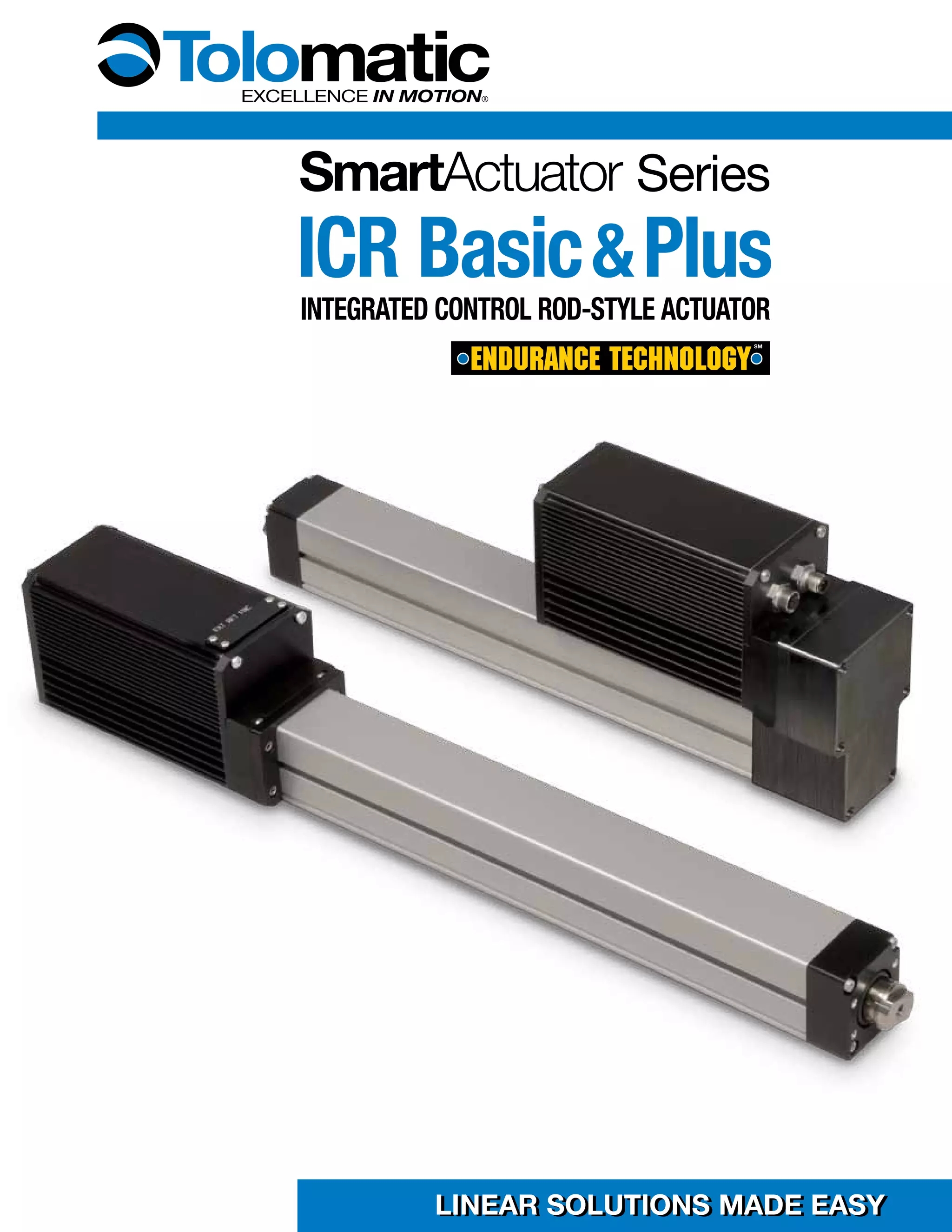
Actuator Dimensions - LMI
ICR Plus
2.36 [60.0]
1.60
[40.7]
0.88
[22.2]
0.70 [17.8]
CAN Open Option
1.81
[45.9]
ICR Basic
CAN Open
Option
M8-1.25
0.75 [19.0]
M5-0.8
0.79 [20.0]
BN02
14.33
[364.0]
+
STROKE
BN05
11.63
[295.4]
+
STROKE
BOTTOM
VIEW
M5 x 0.8 6H
0.25 [6.3] (4)
BN02
6.32
[160.5]
+
STROKE
BN05
3.62
[92.1]
+
STROKE
0.64
[16.3]
0.77
[19.5]
1.06
[26.9]
0.984
[25.00]
0.28
[7.1]
56.0
[2.20]
0.59
[15.0]
2.00
[50.8]
1.10
[28.0]
6.31 [185.8]
[160.3]
3.14 [79.8]
3.94
[100.0]
7.31
0.50
[12.7]
0.51
[12.9]
2.09
[53.1]
1.56
[39.5]
1.75
[44.5]
1-800-328-2174 www.tolomatic.com ICR_17](https://image.slidesharecdn.com/2100-40000105icrcat-141027101616-conversion-gate01/75/Electric-Intelligent-Actuators-Electric-Smart-Actuators-ICR-17-2048.jpg)
![Series ICR Basic & ICR Plus 3d cad available at
www.tolomatic.com
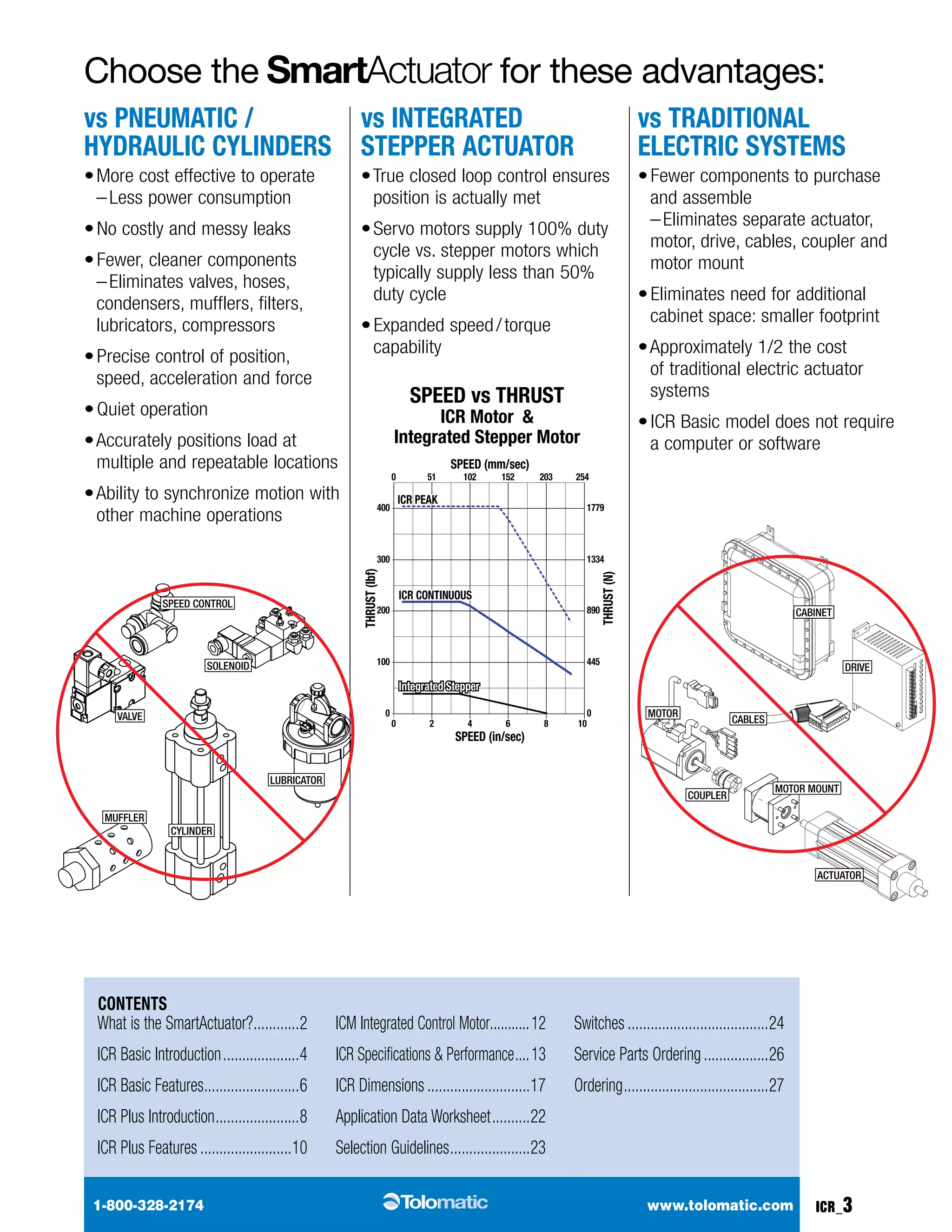
Actuator Dimensions -RP
2.20
[56.0]
0.88
[22.2]
1.75
[44.5]
3.14
[79.8]
9.09
[230.9]
0.59 [15.0]
0.26 [6.6]
M5 x 0.8 - 6H
0.79 [20.1]
1.60
[40.7]
2.31
[58.7]
0.984
[25.00]
2.00
[50.8]
Ø1.10
[28.0]
ICR Plus
M5 x 0.8 - 6H
0.25 [6.4]
3.94 [100.0]
M8 x 1.25 - 6H
0.75 [19.1]
6.57 6.32
[166.8] [160.5]
BN02
6.24
[158.4]
+
STROKE
BN05
3.57
[90.7]
+
STROKE
BN02
9.71
[246.7]
+
STROKE
BN05
7.01
[178.1]
+
STROKE
CAN Open
Option
ICR Basic
ICR_18 1-800-328-2174 www.tolomatic.com](https://image.slidesharecdn.com/2100-40000105icrcat-141027101616-conversion-gate01/75/Electric-Intelligent-Actuators-Electric-Smart-Actuators-ICR-18-2048.jpg)
![Series ICR Basic & ICR Plus 3d cad available at
www.tolomatic.com
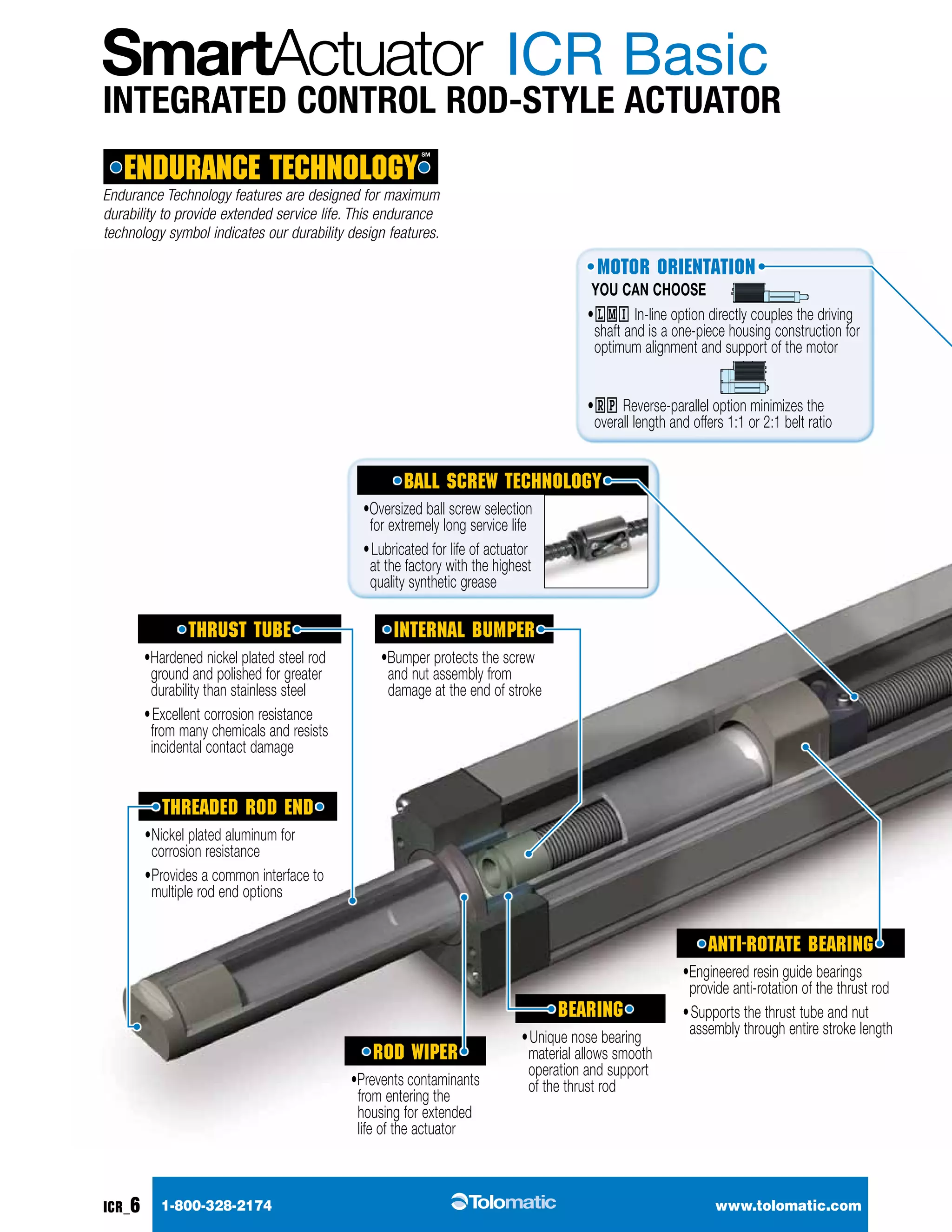
Actuator option Dimensions - LMI
1.00
[25.4]
BRAKE IP65
BN02
16.40
[416.5]
+
STROKE
BNO5
13.70
[348.0]
+
STROKE
2.07
[52.6]
1.00
[25.4]
4.00
[101.6]
3.39
[86.0]
2.63
[66.7]
MOUNTING
PLATE HM2 TUBE CLAMP TC
FFG - Front Flange Mount
1.00
[25.4]
0.53
[13.5]
MOUNTING
PLATE MP
1.22
[31.1]
1.03
[26.2]
4.00
[101.6]
1.03
[26.2]
3.39
[86.0]
1.00
[25.4]
TRUNNION
BN02
7.51
[190.8]
+
STROKE
BNO5
4.81
[122.2]
+
STROKE
TRUNNION
MOUNT TRN
0.45
[11.5] Ø.563
BN02
14.60
[370.8]
+
STROKE
BNO5
11.90
[302.3]
+
STROKE
1.22
[31.1] 4.05
[102.8]
0.45
[11.5]
[14.29]
Ø.4717 11.981
0.4728 12.009
3.15 [80.0]
2.520 [64.00]
1.57
[40.0]
0.31 [8.0]
0.77 [19.6]
R 0.25 [6.4] (4)
0.93
[23.5]
Ø.28 [7.2]
THRU (4)
Ø.206 [5.23] THRU
Ø.38 [9.5] 0.22 [5.6]
4 HOLES
0.875
[22.23]
0.49 [12.4]
0.30 [7.5]
Ø 1.34 [34.0] THRU
1.603
[40.72]
1.260
[32.00]
1.85
[47.0]
0.39
[10.0]
1-800-328-2174 www.tolomatic.com ICR_19](https://image.slidesharecdn.com/2100-40000105icrcat-141027101616-conversion-gate01/75/Electric-Intelligent-Actuators-Electric-Smart-Actuators-ICR-19-2048.jpg)
![Series ICR Basic & ICR Plus 3d cad available at
www.tolomatic.com
Actuator option Dimensions - RP
2.07
[52.6]
10.93
[277.7]
1.00
[25.4]
3.50
[88.9]
Ø.22
[5.6]
BRAKE
1.00
[25.4]
4.00
[101.6]
MOUNTING
PLATE HM2
4.00
[101.6]
IP65
1.00
[25.4]
0.53
[13.5]
3.50
[88.9]
Ø.22
[5.6]
1.22
[31.1]
1.03
[26.2]
MOUNTING
PLATE MP
TUBE
CLAMP TC
TRUNNION CLEVIS
BN02
10.82
[274.8]
+
STROKE
BN05
8.08
[205.2]
STROKE
1.06
[27.0] 0.69
[17.5]
1.240
[31.50]
REAR CLEVIS MOUNT PCD
Ø.500
.498
12.70
12.65
1.10
[28.0]
1.98
[50.3]
+
1.10 [28.0]
BN02
7.09
[180.1]
+
STROKE
BN05
4.39
[111.5]
+
STROKE
4.85 [123.2]
Ø .472
.471
11.99
11.96
3.14
[79.9]
0.47
[11.9]
TRUNNION
MOUNT TRN
ICR_20 1-800-328-2174 www.tolomatic.com](https://image.slidesharecdn.com/2100-40000105icrcat-141027101616-conversion-gate01/75/Electric-Intelligent-Actuators-Electric-Smart-Actuators-ICR-20-2048.jpg)
![Series ICR Basic & ICR Plus 3d cad available at
www.tolomatic.com
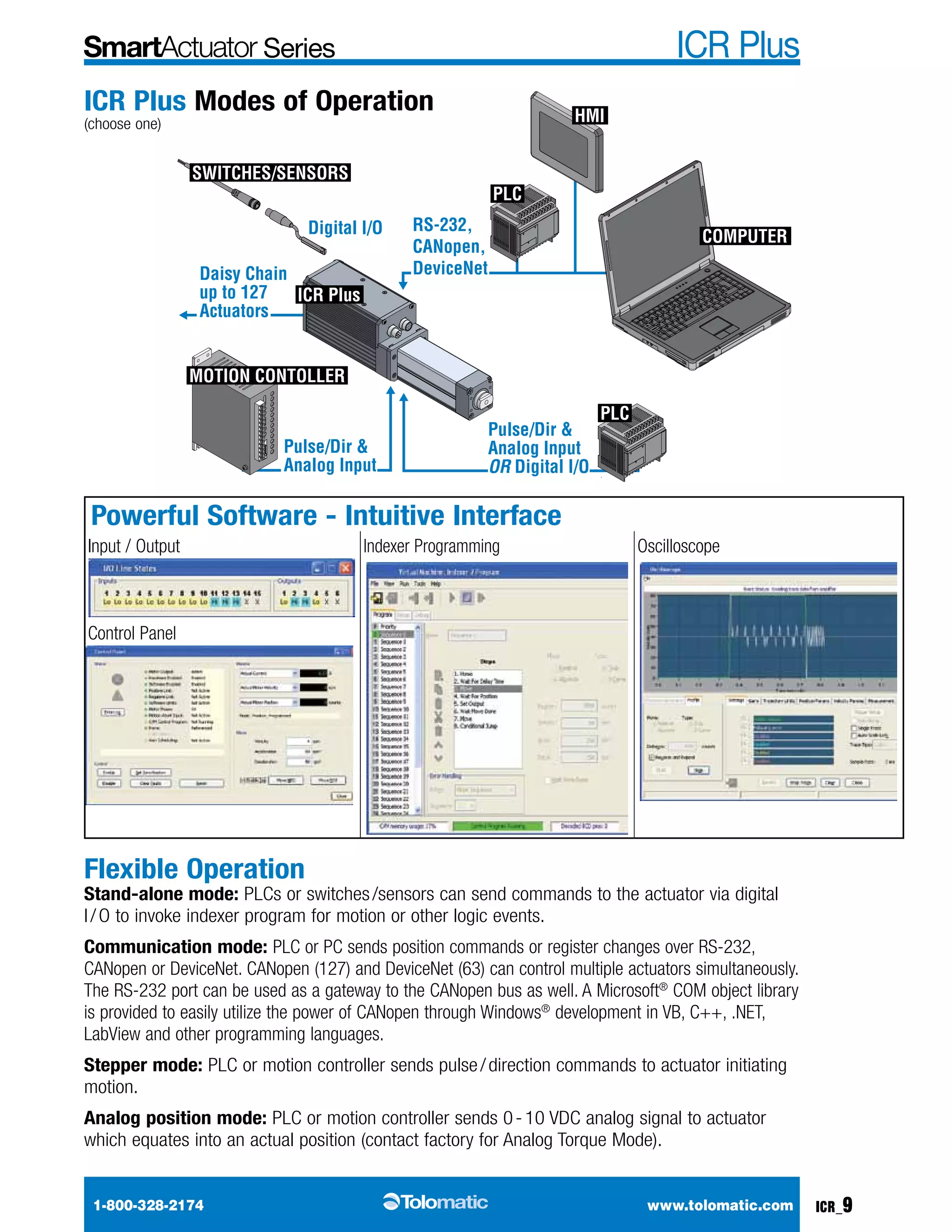
Actuator Rod End option Dimensions
OPTIONAL Spherical Rod Eye End: SRE
Ø.315
[8.00]
Ø.945 [24.00]
0.904
[22.95]
0.457
[11.60]
0.354 [9.00]
OPTIONAL Alignment Coupler Rod End: ALC
36°
0.157 [4.00]
JAM NUT
INTERNALLY THREADED END SPECIFIED EXTERNALLY THREADED END SPECIFIED
0.15 [3.8] JAM NUT 0.15 [3.8] JAM NUT
2.79 [70.8]
0.787
[20.0]
0.75 [24.0]
M8 x 1.25
2° SPHERICAL MOTION,
0.0625 [1.6] RADIAL FLOAT
0.15 [3.8] JAM NUT
MET OPTION
1.14
[29.0]
M8 x 1.25
Ø 1.25 [31.7]
OPTIONAL External Threaded Rod End: MET
0.48
0.394
[10.0]
0.50
[12.7]
0.50
[12.7]
M8 x 1.25 M8 x 1.25 [12.2]
0.10
[2.5]
0.10
[2.5]
0.51
[13.0] 1.26
[32.0]
M8 - 1.25 - 6H
OPTIONAL Clevis Rod End: CLV
0.319 [8.10]
0.318 [8.07]
PIN Ø INCLUDED
0.79 SQ.
[20.0]
0.63 [16.0]
0.237 [6.01]
0.242 [6.14]
THE ALIGNMENT COUPLER COMES WITH AN
INTERNAL THREAD. IF AN EXTERNAL
THREAD IS PREFERRED, THE ADDITION OF
THE ''MET'' OPTION IS REQUIRED.
1-800-328-2174 www.tolomatic.com ICR_21](https://image.slidesharecdn.com/2100-40000105icrcat-141027101616-conversion-gate01/75/Electric-Intelligent-Actuators-Electric-Smart-Actuators-ICR-21-2048.jpg)

![Series ICR Basic & ICR Plus
Order
Code
Part
Number
Lead
Switching
Logic
Power
LED
Signal
LED
Operating
Voltage
**Power
Rating
(Watts)
Switching
Current
(mA max.)
Current
Consumption
Voltage
Drop
Leakage
Current
81009090
81009090
81009090
81009090
81009090
81009090
1-800-328-2174 www.tolomatic.com
ICR_24
*QD = Quick-disconnect Enclosure classification IEC 529 IP67 (NEMA 6) CABLES: Robotic grade, oil resistant polyurethane jacket, PVC insulation
**WARNING: Do not exceed power rating (Watt = Voltage x Amperage). Permanent damage to sensor will occur.
Temp.
Range
Shock /
Vibration
RED
RY 8100-9082 5m SPST
Normally
Open
— Red
5 - 240
AC/DC
**10.0 100mA —
3.0 V
max.
—
14
to
158°F
[-10
to
70°C]
50 G /
9 G
RK 8100-9083 QD* 81009082
81009084
81009088
81009092
81009094
NY 8100-9084 5m SPST
Normally
Closed
— Yellow
5 - 110
AC/DC
NK 8100-9085 QD*
81009082
81009084
81009088
81009092
81009094
SOLID
STATE
TY 8100-9088 5m PNP
(Sourcing)
Normally
Open
Green Yellow
10 - 30
Vdc
**3.0 100mA
20 mA
@
24V
2.0 V
max.
0.05
mA
max.
TK 8100-9089 QD*
81009082
81009084
81009088
81009092
81009094
KY 8100-9090 5m NPN
(Sinking)
Normally
Open
Green Red
KK 8100-9091 QD*
81009082
81009084
81009088
81009092
81009094
PY 8100-9092 5m PNP
(Sourcing)
Normally
Closed
Green Yellow
PK 8100-9093 QD*
81009082
81009084
81009088
81009092
81009094
HY 8100-9094 5m NPN
(Sinking)
Normally
Closed
Green Red
HK 8100-9095 QD*
81009082
81009084
81009088
81009092
81009094
Switches
Specifications
ICR products offer a wide range of sensing choices. There are 12 switch choices:
reed, solid state PNP (sourcing) or solid state NPN (sinking); in normally open or
normally closed; with flying leads or quick-disconnect.
Commonly used for end-of-stroke positioning, these switches allow drop-in installation
anywhere along the entire actuator length. The one-piece design includes the retained
fastening hardware and is designed for the slot on either the left or right side of the
actuator. The magnet is a standard feature and is internally located in the anti-rotate
bearing. See the dimensional drawings on page icr_25 for details of switch locations.
Switches can be installed in the field at any time.
Switches are used to send digital signals to PLC (programmable logic controller), TTL, CMOS
circuit or other controller device. Switches contain reverse polarity protection. Solid state QD
cables are shielded; shield should be terminated at flying lead end.
All switches are CE rated and are RoHS compliant. Switches feature bright red or yellow LED
signal indicators; solid state switches also have green LED power indicators. RoHS
COMPLIANT
Switch installation and replacement
Place switch in side groove on tube at desired location with "Tolomatic"
facing outward. While applying light pressure to the switch, rotate the
switch halfway into the groove. Maintaining light pressure, rotate the
switch in the opposite direction until it is fully inside the groove with
"Tolomatic" visible. Re-position the switch to the exact location and lock
the switch securely into place by tightening the screw on the switch.
Insert
switch
Rotate
switch
Secure
switch
Tolomatic
Tolomatic
Tolomatic](https://image.slidesharecdn.com/2100-40000105icrcat-141027101616-conversion-gate01/75/Electric-Intelligent-Actuators-Electric-Smart-Actuators-ICR-24-2048.jpg)
![Series ICR Basic & ICR Plus
BLACK BLUE (-)
(SIGNAL)
MOUNTING DIMENSIONS
connect
DETECTION POINT REED
SWITCH DIMENSIONS MOUNTING DIMENSIONS
_ Y - direct connect
_ K - QD (Quick-disconnect) switch
Quick-disconnect) switch
DETECTION POINT REED
.51 [13]
1.26 [32.1]
.95 [24.1]
SWITCHES SIT BELOW
TUBE EXTRUSION PROFILE
1-800-328-2174 www.tolomatic.com
ICR_25
Wiring diagrams
NORMALLY
CLOSED
BRN
BLU
+
-
LOAD
NORMALLY
CLOSED
BRN
BLU
+
LOAD -
or
NORMALLY
OPEN PNP
(SOURCING)
BRN
BLK
+
SIGNAL
LOAD
BLU -
NORMALLY
OPEN NPN
(SINKING)
BRN
BLK
+
SIGNAL
LOAD
BLU -
NORMALLY
CLOSED PNP
(SOURCING)
BRN
BLK
+
SIGNAL
LOAD
BLU -
NORMALLY
CLOSED NPN
(SINKING)
BRN
BLK
+
SIGNAL
LOAD
BLU -
NORMALLY
OPEN
BRN
BLU
+
-
LOAD
NORMALLY
OPEN
BRN
BLU
+
LOAD -
or
TY, #8100-9088, • TK, #8100-9089
SOLID STATE • NORMALLY OPEN • PNP
NY, #8100-9084, • NK, #8100-9085
REED • NORMALLY CLOSED
QUICK DISCONNECT MALE PLUG PINOUT #8100-9080 QUICK DISCONNECT
FEMALE SOCKET PINOUT
RY, #8100-9082, • RK, #8100-9083
REED • NORMALLY OPEN
KY, #8100-9090, • KK, #8100-9091
SOLID STATE • NORMALLY OPEN • NPN
PY, #8100-9092, • PK, #8100-9093
SOLID STATE • NORMALLY CLOSED • PNP
HY, #8100-9094, • HK, #8100-9095
SOLID STATE • NORMALLY CLOSED • NPN
BROWN (+)
BLUE (-)
BROWN (+)
BLACK
(SIGNAL)
Switches
Siwtch DIEMNSINOS MNOTUIGN DIEMNSINOS
ICR20
.51 [13]
30]
32.1]
.95 [24.1]
7]
13.35 [339]
M8x1
197 [5000]
1.10 [27.9]
197 [5000]
QD Cable
SWITCHES SIT BELOW
TUBE EXTRUSION PROFILE
Dimensions in inches [brackets indicate dimensions in millimeters]
16, 25, 32
40, 50, 63
1.18 [30]
.31 [8]
Ø.28 [7]
DETECTION POINT
SOLID STATE
13.35 [339]
M8x1
M8x1
197 [5000]
197 [5000]
8100-9080 - QD Cable
U
SWITCHES SIT BELOW
TUBE EXTRUSION PROFILE
V
U
Ø.35
[9]
W
V
X](https://image.slidesharecdn.com/2100-40000105icrcat-141027101616-conversion-gate01/75/Electric-Intelligent-Actuators-Electric-Smart-Actuators-ICR-25-2048.jpg)


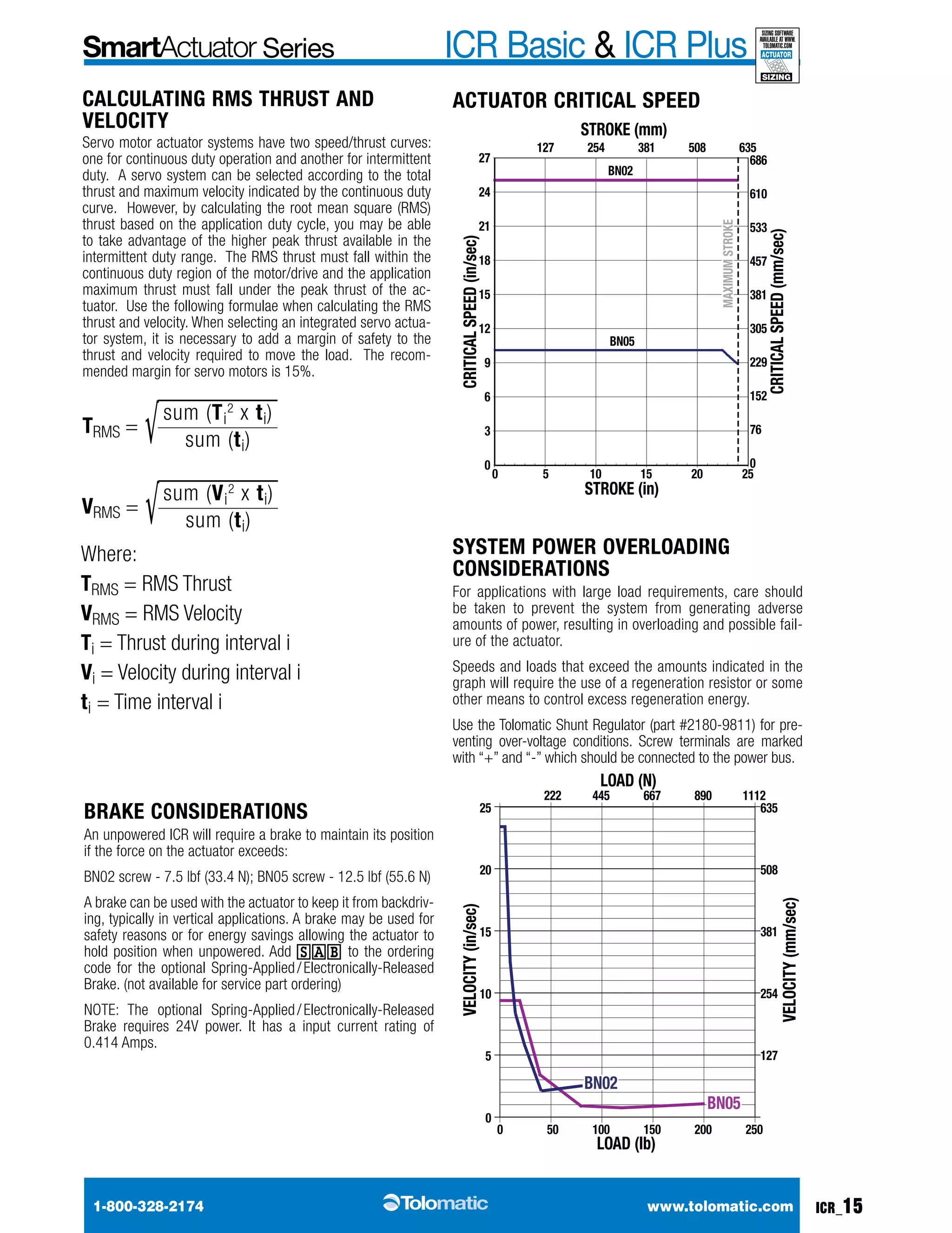
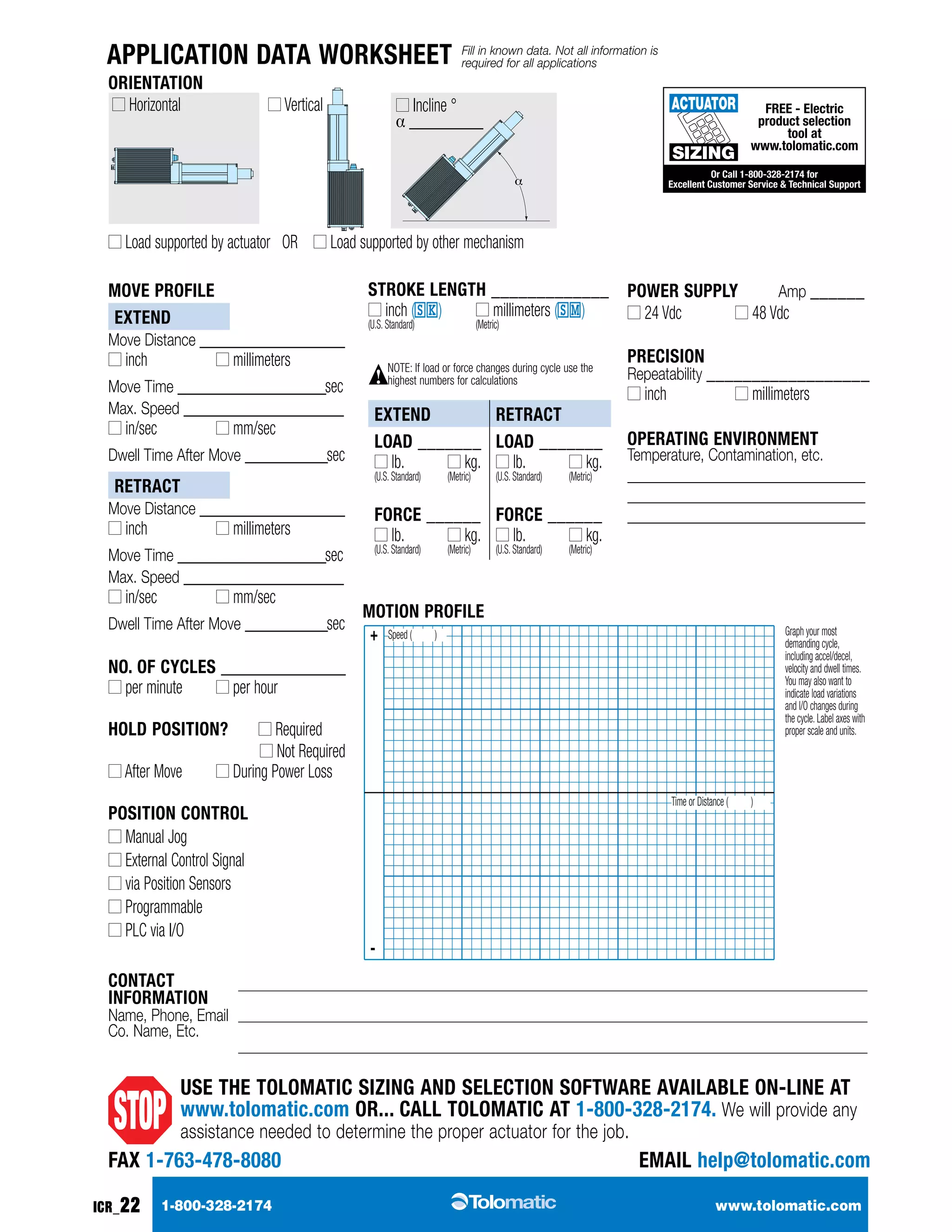
The document describes the ICR Basic and ICR Plus, which are integrated electric rod-style actuators by Tolomatic, featuring ease of installation and operation, with capabilities for various industrial applications. The ICR Basic offers straightforward extend/retract functionality, while the ICR Plus includes advanced features like indexing, network communication, and programmable motion profiles. Both models emphasize efficiency, precision control, and durability, making them suitable replacements for pneumatic and hydraulic systems.


