Downloaded 135 times
![F T ra n sf o F T ra n sf o
PD rm PD rm
Y Y
Y
Y
er
er
ABB
ABB
y
y
bu
bu
2.0
2.0
to
to
re
re
J3103/5/13
he
he
k
k
lic
lic
POWER PRESS MACHINE
C
C
w om w om
w
w
w. w.
A B B Y Y.c A B B Y Y.c
5.1.4. Stop
There are many forms of stops, the one shown being a simple spring
loaded type. As the strip is pushed under the stop it rides up over the strip
to drop into the space left by the blank. If the strip is then pulled back
against the stop (against the direction of feed), the strip is correctly
located for the next shearing operation, leaving the minimum of waste
metal between the blanked holes. This feeding operation up to a stop can
be carried out at high speed by the operator, and a well designed stop
must be simple and efficient in use.
More complex tools may require more than one stop, and
arrangements can be made to operate stops by the movement of the press
ram if desired. Automatic feed devices do not require soon as the strip is
automatically moved along the correct pitch length, between each stroke
of the press.
5.1.5. Pilot
These are held in the blanking punch and are a clearance fit for the
pierced hole. As the ram descends, the pilot locates the previously pierced
hole and positions the strip more precisely under the blanking punch.
Pilots are used where the relationship of pierced holes to a blank profile
must be precise; therefore a stop initially positions the strip, but the final
positioning depends upon the pilot. It can be seen then that this
technique is ideal for a roll feed press which has no stops upon the too].](https://image.slidesharecdn.com/unit5powerpressmachine-100123220328-phpapp02/85/Unit5-Power-Press-Machine-13-320.jpg)
![F T ra n sf o F T ra n sf o
PD rm PD rm
Y Y
Y
Y
er
er
ABB
ABB
y
y
bu
bu
2.0
2.0
to
to
re
re
J3103/5/27
he
he
k
k
lic
lic
POWER PRESS MACHINE
C
C
w om w om
w
w
w. w.
A B B Y Y.c A B B Y Y.c
Example 5.4
A cup is to be drawn to a diameter of 76.2 mm x 38-0 mm deep in 0.8mm thick
material. Estimate the blank diameter and the maximum drawing force if su
= 432 N/mm2
Solution
D= d 2 + 4dh
= 5800 + (4 x 76.2 x 38.0)
= 5800 + 11600
= 17400
= 132 mm
D 132
Drawing ratio = =
d 76 .2
= 1.73
assume the cup can be drawn in one operation.
Fmax = p. d. t. su
= 3.142 x 76.2 x 0.8 x 0.432 = 0-083 MN
5.7. COMBINATION TOOLS
It is often possible where batch quantities justify it to incorporate two
operations into the one too] such that the operations are carried out in
combination. This increases the production rate hence reducing the variable
costs with little increase in fixed costs. The dual operation is usually blank and
draws and is very successful on thin materials where the total force required is
not impracticable, and the component can be drawn to full depth in the one
operation. Figure 5.12 shows the principle of operation of such a too].](https://image.slidesharecdn.com/unit5powerpressmachine-100123220328-phpapp02/85/Unit5-Power-Press-Machine-27-320.jpg)
![F T ra n sf o F T ra n sf o
PD rm PD rm
Y Y
Y
Y
er
er
ABB
ABB
y
y
bu
bu
2.0
2.0
to
to
re
re
J3103/5/28
he
he
k
k
lic
lic
POWER PRESS MACHINE
C
C
w om w om
w
w
w. w.
A B B Y Y.c A B B Y Y.c
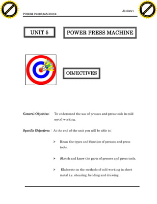
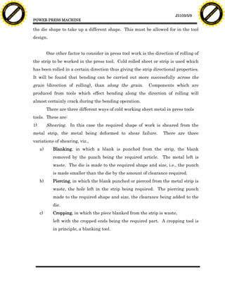
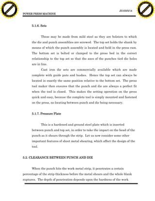
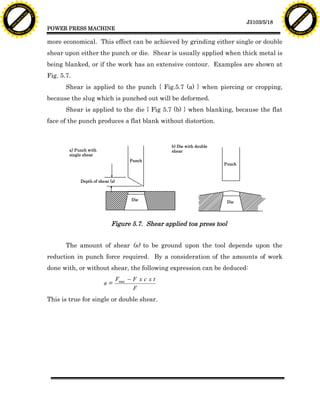
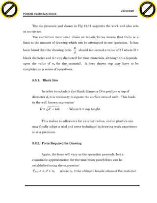
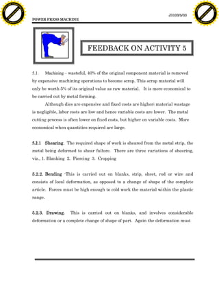
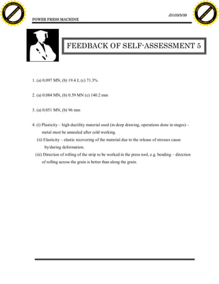
The punch blanks upon diameter D and draws on diameter d. The punch
and die pressure pads are spring loaded. As the punch descends in the guide, it
shears the blank from the strip, and the blank will be gripped between the
punch face and the pressure pads. The punch continues to descend, and the
blank is drawn over the drawing die. The drawn cup is in an inverted position to
that shown in Fig 5.12.
D
Punch (blanking
Fixed punch guide & drawing)
Pressure pads
d Drawing die Strip
Fig 5.12. Combination Too].
As the punch withdraws, the pressure pads act as ejectors so that the cup
does not stick to the die or punch. The punch guide can also be arranged to act
as a stripper, so that the strip is removed from the punch.
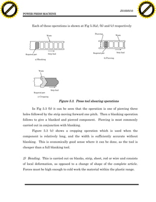
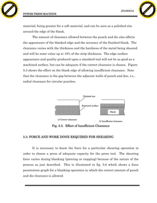
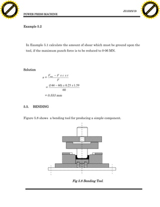
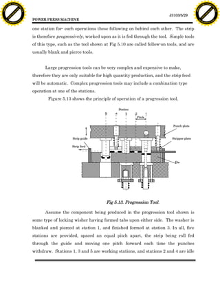
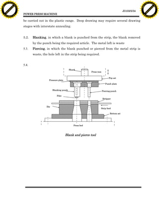
5.8. PROGRESSION TOOL
The combination tool described in the previous section combines more
than one press operation at the one tool station, and the punches and dies are
positioned on the same axis. A progression tool, by contrast, has more thin one
press operation positioned at separate stations oil the press tool set, i.e., there is](https://image.slidesharecdn.com/unit5powerpressmachine-100123220328-phpapp02/85/Unit5-Power-Press-Machine-28-320.jpg)

![F T ra n sf o F T ra n sf o
PD rm PD rm
Y Y
Y
Y
er
er
ABB
ABB
y
y
bu
bu
2.0
2.0
to
to
re
re
J3103/5/35
he
he
k
k
lic
lic
POWER PRESS MACHINE
C
C
w om w om
w
w
w. w.
A B B Y Y.c A B B Y Y.c
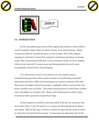
5.5.
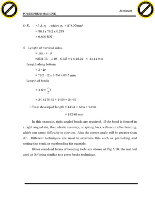
D
Punch (blanking
Fixed punch guide
& drawing)
Pressure pads
d Drawing die Strip
Blanking die
Combination Too].
Station
Pitch
Punch plate
Strip guide Stripper plate
Strip feed
Die
Progression Tool.](https://image.slidesharecdn.com/unit5powerpressmachine-100123220328-phpapp02/85/Unit5-Power-Press-Machine-35-320.jpg)


This document discusses power press machines and their use in cold metal working. It introduces the objectives of understanding the types and functions of presses and press tools, being able to sketch their parts, and elaborating on methods of cold working sheet metal through shearing, bending, and drawing. It then provides background on how metal forming can be more economical than metal cutting for large production quantities due to lower variable costs, despite higher fixed costs for dies. The document focuses on using presses and press tools for cold working metal objects into shape, especially ductile sheet or strip metals.