
![INTERNSHIP TRAINING PROGRAM REPORT(INDUSRTIAL AWARENESSPROGRAM) January 25, 2018
57HMT Machine Tools Limited, हिन्दुस्तान मशीन टू ल्स हिहमटेड
in some cases has been partly marketing psychology. For name-brand machine tool builders who made
only high-quality tools, there wasn't necessarily any lack of quality in the base-model product for the
"luxury model" to improve upon. In other cases,especially when comparing different brands, the quality
differential between (1) an entry-level center lathe built to compete on price, and (2) a tool room lathe
meant to compete only on quality and not on price, can be objectively demonstrated by measuring TIR,
vibration, etc. In any case, because of their fully ticked-off option list and (real or implied) higher
quality, tool room lathes are more expensive than entry-level center lathes.
Turret lathe and capstan lathe
Turret lathes and capstan lathes are members of a class of lathes that are used for repetitive production
of duplicate parts (which by the nature of their cutting process are usually interchangeable). It evolved
from earlier lathes with the addition of the turret,which is an indexable toolholder that allows multiple
cutting operations to be performed, each with a different cutting tool, in easy,rapid succession, with no
need for the operator to perform setup tasks in between (such as installing or uninstalling tools) nor to
control the toolpath. (The latter is due to the toolpath's being controlled by the machine, either in jig-
like fashion [via the mechanical limits placed on it by the turret's slide and stops] or via IT-directed
servomechanisms [on computer numerical controlled (CNC) lathes].)
There is a tremendous variety of turret lathe and capstan lathe designs, reflecting the variety of work
that they do.
Gang-tool lathe
A gang-tool lathe is one that has a row of tools set up on its cross-slide, which is long and flat and is
similar to a milling machine table. The idea is essentially the same as with turret lathes: to set up
multiple tools and then easily index between them for each part-cutting cycle. Instead of being rotary
like a turret, the indexable tool group is linear.
HMT basically concentrates on production of L-45 lathes.
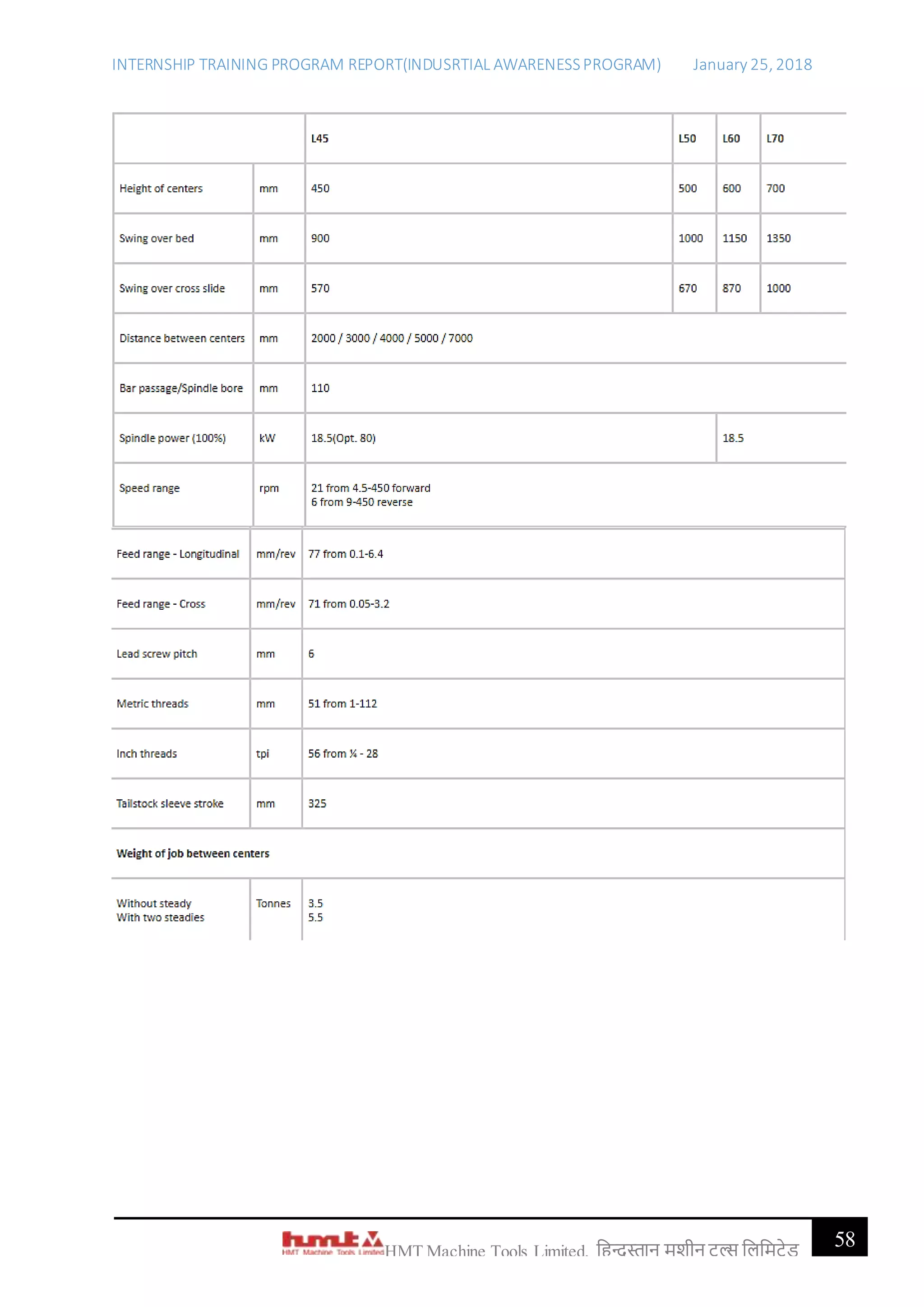
Heavy Duty Lathe L45
Bringing economy, precision and speed into
heavy machine shop.
Salient Features :
Box type construction of bed with flame hardened bed guideways.
Main spindle supported by two Timken taper roller bearings in front which dampen
vibrations during heavy cuts and at rear supported by precision NNK bearings.
All gears in main drive and feed drive of ally steel, case hardened and ground.](https://image.slidesharecdn.com/internshiptrainingprogramreport-181031034126/75/HMT-Internship-training-program-report-57-2048.jpg)
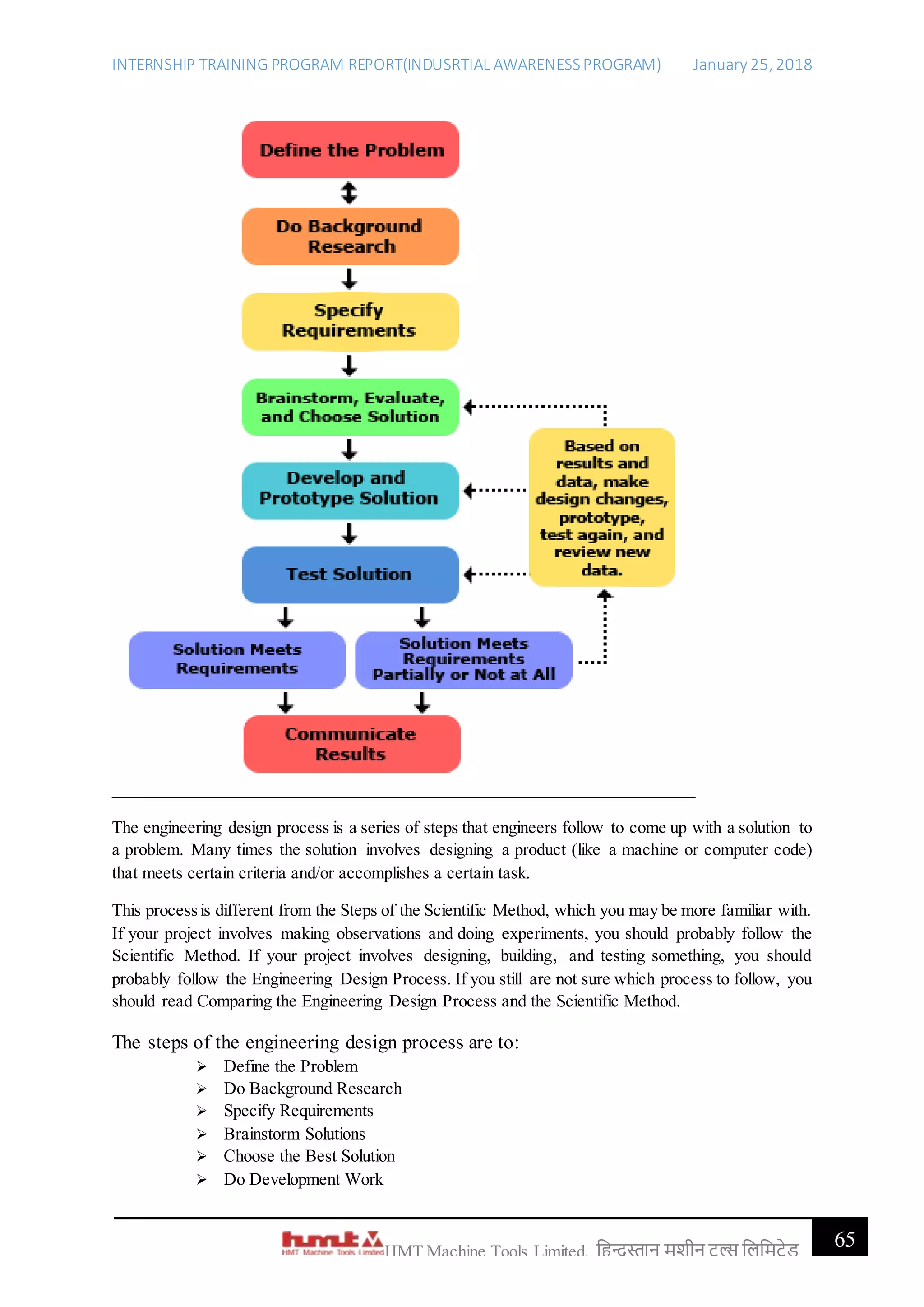

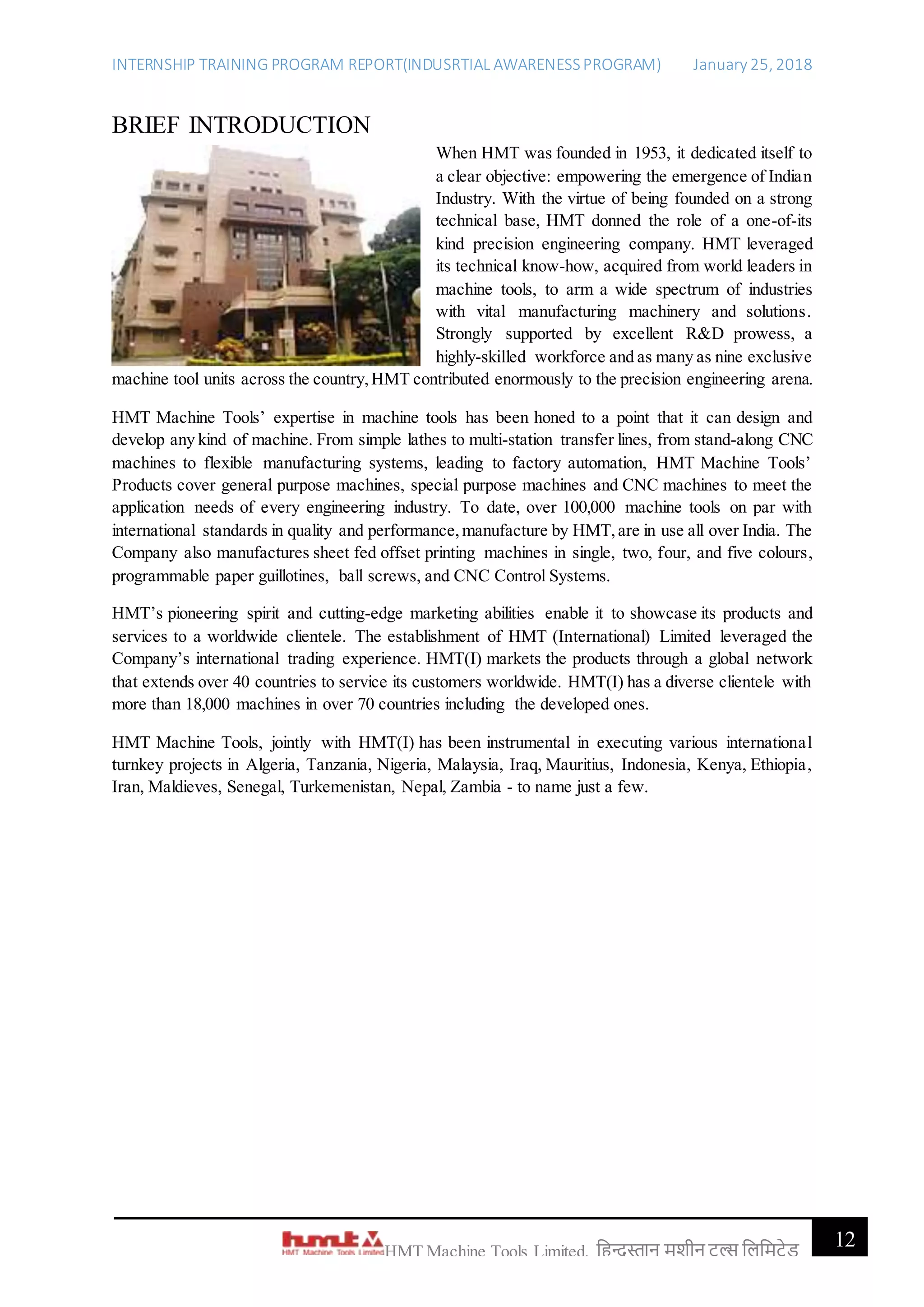
The document is an internship training program report by Satyajeet Malla detailing his experience at HMT Machine Tools Limited, a prominent state-owned manufacturing company in India. It provides insights into the company's history, corporate structure, vision and mission, and highlights various manufacturing units and processes involved in machine tool production. The report emphasizes the internship as a valuable opportunity for professional development and acknowledges the guidance received from company personnel.