The document discusses the design and optimization of a hexa-band MIMO bowtie antenna using particle swarm optimization (PSO), capable of operating at six frequency bands (2.4, 4.4, 6.1, 8.5, 10.25, and 12.8 GHz). It presents simulation results demonstrating low mutual coupling between antenna elements and emphasizes the efficiency and effectiveness of the design. The antenna's performance surpasses previous designs in terms of operational frequency bands and complexity, highlighting significant advancements in MIMO antenna technology.
![International Journal of Electrical and Computer Engineering (IJECE)
Vol. 8, No. 5, October 2018, pp. 3118~3128
ISSN: 2088-8708, DOI: 10.11591/ijece.v8i5.pp3118-3128 3118
Journal homepage: http://iaescore.com/journals/index.php/IJECE
Hexa-band MIMO CPW Bow-tie Aperture Antenna Using
Particle Swarm Optimization
A-K. Hamid, W. Obaid
Department of Electrical and Computer Engineering, College of Engineering, University of Sharjah, UAE
Article Info ABSTRACT
Article history:
Received Sep 7, 2017
Revised Jan 17, 2018
Accepted Aug 24, 2018
A MIMO hexa-band Bowtie Antenna for Wi-Fi is proposed. The MIMO
antenna can operate at six frequency bands: 2.4, 4.4, 6.1, 8.5, 10.25 and 12.8
GHz. The MIMO antenna consists of four loaded bowtie hexa-band antennas
having the same structure. Each single antenna element is loaded with six
metallic strips as well as interconnected parasitic rectangular components.
The presented HFSS simulations will show that the MIMO loaded antenna
can operate at six frequency bands including 2.4 GHz by obtaining the return
loss results, radiation patterns, and other antenna parameters. It will be
shown also that the MIMO bowtie antenna has a very low mutual coupling at
all the operating frequencies for the specific loaded metallic strips width
which was obtained using Particle Swarm Optimization technique.
Keyword:
Hexa-band
HFSS
MIMO bowtie antenna
Mutual coupling
Particle Swarm Optimization Copyright © 2018 Institute of Advanced Engineering and Science.
All rights reserved.
Corresponding Author:
A-K. Hamid,
Department of Electrical and Computer Engineering,
College of Engineering, University of Sharjah, Sharjah, UAE.
Email: akhamid@sharjah.ac.ae
1. INTRODUCTION
Many optimization methods were developed in the last decades such as the Genetic Algorithm,
Particle Swarm Optimization and others for optimizing the antennas and their parameters [1]. Optimizing
antenna parameters using such techniques is very important in order to obtain significant results related to
different antenna parameters such as the return loss or impedance. Obtaining such improved antenna
parameters using optimization techniques makes adding extra components on the antenna to achieve similar
results to be dispensable.
Genetic Algorithm is an optimization method which performs mutation, crossover, and selection
over a set of possible individuals. It can take a list of constraints for evaluating the objective function in order
to maximize or minimize a specific variable [2]. Particle Swarm Optimization is a much simpler algorithm
than Genetic Algorithm and more efficient in terms of computation time. It is a population-based stochastic
technique. The iterations in this technique improve the wanted outcome until reaching the desired solution as
the case of bird flocking behavior [3]. A design for a spline-shaped antenna was proposed using PSO in [4]
for Ultra-wide-band applications. Another optimization design relied on both the Genetic Algorithm and PSO
for designing a horn antenna in [5].
Bowtie antenna is very suitable for communication and Wi-Fi technologies and applications because
it has some unique features such are the ability to operate at multiple frequencies, the minimum cost of
manufacturing, the small size and the lightweight [6]. There were many designs for the bowtie antenna
related to tri-band frequency operations such as the ones in [7]-[13]. Other designs were presented to make
the antenna at Penta-frequency bands as in [14 - 16]. Hexa-band antenna designs were presented for various
applications such as GSM, GPS-L1, WLAN, WiMAX and mobile handset applications [17]-[18].
MIMO antenna designs require reducing the mutual coupling between elements of the antenna.
Dual-band Dual-polarized antenna array was proposed in [19] for WLAN. A tri-band E-shaped antenna was](https://image.slidesharecdn.com/v527sep1717jan188612-14889-1-ededitari-201118065637/85/Hexa-band-MIMO-CPW-Bow-tie-Aperture-Antenna-Using-Particle-Swarm-Optimization-1-320.jpg)
![International Journal of Electrical and Computer Engineering (IJECE)
Vol. 8, No. 5, October 2018, pp. 3118~3128
ISSN: 2088-8708, DOI: 10.11591/ijece.v8i5.pp3118-3128 3118
Journal homepage: http://iaescore.com/journals/index.php/IJECE
Hexa-band MIMO CPW Bow-tie Aperture Antenna Using
Particle Swarm Optimization
A-K. Hamid, W. Obaid
Department of Electrical and Computer Engineering, College of Engineering, University of Sharjah, UAE
Article Info ABSTRACT
Article history:
Received Sep 7, 2017
Revised Jan 17, 2018
Accepted Aug 24, 2018
A MIMO hexa-band Bowtie Antenna for Wi-Fi is proposed. The MIMO
antenna can operate at six frequency bands: 2.4, 4.4, 6.1, 8.5, 10.25 and 12.8
GHz. The MIMO antenna consists of four loaded bowtie hexa-band antennas
having the same structure. Each single antenna element is loaded with six
metallic strips as well as interconnected parasitic rectangular components.
The presented HFSS simulations will show that the MIMO loaded antenna
can operate at six frequency bands including 2.4 GHz by obtaining the return
loss results, radiation patterns, and other antenna parameters. It will be
shown also that the MIMO bowtie antenna has a very low mutual coupling at
all the operating frequencies for the specific loaded metallic strips width
which was obtained using Particle Swarm Optimization technique.
Keyword:
Hexa-band
HFSS
MIMO bowtie antenna
Mutual coupling
Particle Swarm Optimization Copyright © 2018 Institute of Advanced Engineering and Science.
All rights reserved.
Corresponding Author:
A-K. Hamid,
Department of Electrical and Computer Engineering,
College of Engineering, University of Sharjah, Sharjah, UAE.
Email: akhamid@sharjah.ac.ae
1. INTRODUCTION
Many optimization methods were developed in the last decades such as the Genetic Algorithm,
Particle Swarm Optimization and others for optimizing the antennas and their parameters [1]. Optimizing
antenna parameters using such techniques is very important in order to obtain significant results related to
different antenna parameters such as the return loss or impedance. Obtaining such improved antenna
parameters using optimization techniques makes adding extra components on the antenna to achieve similar
results to be dispensable.
Genetic Algorithm is an optimization method which performs mutation, crossover, and selection
over a set of possible individuals. It can take a list of constraints for evaluating the objective function in order
to maximize or minimize a specific variable [2]. Particle Swarm Optimization is a much simpler algorithm
than Genetic Algorithm and more efficient in terms of computation time. It is a population-based stochastic
technique. The iterations in this technique improve the wanted outcome until reaching the desired solution as
the case of bird flocking behavior [3]. A design for a spline-shaped antenna was proposed using PSO in [4]
for Ultra-wide-band applications. Another optimization design relied on both the Genetic Algorithm and PSO
for designing a horn antenna in [5].
Bowtie antenna is very suitable for communication and Wi-Fi technologies and applications because
it has some unique features such are the ability to operate at multiple frequencies, the minimum cost of
manufacturing, the small size and the lightweight [6]. There were many designs for the bowtie antenna
related to tri-band frequency operations such as the ones in [7]-[13]. Other designs were presented to make
the antenna at Penta-frequency bands as in [14 - 16]. Hexa-band antenna designs were presented for various
applications such as GSM, GPS-L1, WLAN, WiMAX and mobile handset applications [17]-[18].
MIMO antenna designs require reducing the mutual coupling between elements of the antenna.
Dual-band Dual-polarized antenna array was proposed in [19] for WLAN. A tri-band E-shaped antenna was](https://image.slidesharecdn.com/v527sep1717jan188612-14889-1-ededitari-201118065637/75/Hexa-band-MIMO-CPW-Bow-tie-Aperture-Antenna-Using-Particle-Swarm-Optimization-1-2048.jpg)
![Int J Elec & Comp Eng ISSN: 2088-8708
Hexa-band MIMO CPW Bow-tie Aperture Antenna Using Particle Swarm … (A-K. Hamid)
3119
proposed for MIMO applications in [20]. One design was proposed for MIMO antenna for a quad-band
operation to be used in wireless communications terminals in [21]. A hexa-band MIMO antenna design was
proposed in [22] for LTE mobile device application which relied on neutralization line concept in order to
reduce the mutual coupling. A design for a 2X2 MIMO patch antenna for multi-band applications was
proposed in [23] using groups of rings at four corners and near the stepped cut in addition to a mid-slot
separation in order to reduce the mutual coupling. Another MIMO antenna design was proposed in [24] for
four-element Dual-band output which had four bowtie dipole antenna, that design had four types of ground
plane patterns which are full, cornered spatial, crossed middle, and spiral. A low mutual coupling dual-band
MIMO microstrip 2X2 antenna with parasitic air gap to reduce the mutual coupling was proposed in [25].
These MIMO antenna designs which were proposed for multiple frequency operations had complicated
structures and they did not have a very low mutual coupling compared to the return losses for their
corresponding MIMO antenna elements.
The proposed MIMO bowtie antenna may operate at six frequency bands by the added six internal
metallic strips and the rectangular interconnected parasitic elements for each MIMO antenna element [26].
The metallic strips are fixed vertically but variable by width horizontally for tuning the frequency. The
interconnected parasitic elements are fixed in their dimensions. The proposed MIMO bowtie antenna consists
of four loaded elements with the same structure; each antenna element is placed at a corner. Next sections
will discuss the structure and the obtained results for the MIMO bowtie antenna.
2. ANTENNA GEOMETRY AND DESIGN
CPW antennas can have variety of shapes such as square, rectangle and triangle. The location of the
antenna feed line is directly related to the radiated cross-polarized components and surface excited currents in
CPW antennas. RF frequency applications, antenna arrays and radar applications are examples of
applications for CPW antennas. The original single unloaded bowtie antenna has the following substrate
(Arlon CuClad 217 (tm) with a 2.17 dielectric constant) dimensions: width=64 mm, length=34 mm and
height=2 mm [27] as shown in Figure 1. It can operate at one frequency band around 10 GHz, The lumped
port feed has 50 Ohms between the CPW antenna feedline.
Figure 1. Dimensions for the unloaded single bowtie antenna: La=42 mm. L=20.5 mm, Wa=12.7 mm,
Lw=12 mm, Ww=0.6 mm, α=52 and P=1 mm [27]
Figure 2 shows the structure for a loaded single MIMO antenna element with the metallic strips and
the interconnected parasitic rectangular components. Figure 3 demonstrates the structure of the MIMO
antenna which consists of four identical loaded antennas with the same structure of metallic strips and
interconnected parasitic rectangular components. The width Ws for the metallic strips was set to a specific
value in order to achieve six frequency bands for all the four loaded antenna elements. The horizontal
distance between the edges of the vertical MIMO element pairs is 22 mm and the vertical distance between
the edges of the horizontal MIMO pairs is 20.6 mm. The dimensions of the MIMO antenna substrate are 128
mm for length and 68 mm for width.](https://image.slidesharecdn.com/v527sep1717jan188612-14889-1-ededitari-201118065637/85/Hexa-band-MIMO-CPW-Bow-tie-Aperture-Antenna-Using-Particle-Swarm-Optimization-2-320.jpg)
![ ISSN: 2088-8708
Int J Elec & Comp Eng, Vol. 8, No. 5, October 2018 : 3118 - 3128
3120
Figure 2 A loaded bowtie antenna element structure with the following dimensions: Ls1=4 mm. Ls2= 13
mm, Ls3=5 mm, Ls4=2.4 mm, Ls5=1.5 mm, Ls6=1 mm, Ls7=14 mm, Ls8=1 mm, Ls9=3 mm, Ls10=6 mm,
Ls11=5 mm
Figure 3 The MIMO antenna structure with the following dimensions: L1=22 mm, L2=20.6 mm and
L3=11 mm
3. SIMULATION RESULTS AND DISCUSSION
The original return loss for the unloaded single antenna is shown in Figure 4 [24]. FR4_epoxy
having a 4.4 dielectric constant material was used as a substrate for the MIMO antenna. Figure 5 shows the
return loss for a single loaded antenna element with a variable Ws. It can be seen from Figure 5 that a single
loaded MIMO antenna element can operate at six different frequency bands by changing the width of the
metallic strips on the surface of the loaded antenna. Figure 6 shows the return loss for the MIMO bowtie
antenna. It can be noticed that the MIMO antenna is able to operate at six frequency bands resulting from
each one of the loaded bowtie MIMO antenna elements with the following return losses: S11, S22, S33, and
S44.
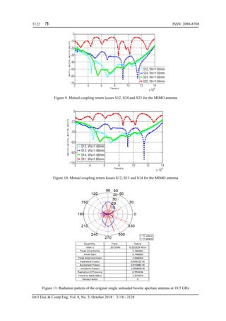
The mutual coupling results between the MIMO antenna elements are shown in Figures 7-10 and it
can be seen that the mutual coupling parameters S12, S13, S14, S23, S24, and S34 are lower than the return
losses S11, S22, S33 and S44 at each of the operating frequency bands when the width of the metallic strips
Ws is 1.66mm. This width value was obtained using Particle Swarm Optimization technique with the
following constraints between the return losses and mutual coupling parameters: S11 >=S12, S22 >=S24,](https://image.slidesharecdn.com/v527sep1717jan188612-14889-1-ededitari-201118065637/85/Hexa-band-MIMO-CPW-Bow-tie-Aperture-Antenna-Using-Particle-Swarm-Optimization-3-320.jpg)
![Int J Elec & Comp Eng ISSN: 2088-8708
Hexa-band MIMO CPW Bow-tie Aperture Antenna Using Particle Swarm … (A-K. Hamid)
3121
S33 >=S31, and S44 >= S42. Figure 11 shows the radiation pattern for the original single unloaded bowtie
antenna in addition to other antenna parameters like the radiation efficiency [24].
Figure 4. Simulation result for S11 for the unloaded bowtie antenna [27]
Figure 5. Return loss S11 for the single loaded
antenna
Figure 6. Return losses S11, S22, S33 and S44 for
the MIMO antenna
Figure 7. Mutual coupling return losses S13, S23 and
S34 for the MIMO antenna
Figure 8. Mutual coupling return losses S14, S34
and S24 for the MIMO antenna](https://image.slidesharecdn.com/v527sep1717jan188612-14889-1-ededitari-201118065637/85/Hexa-band-MIMO-CPW-Bow-tie-Aperture-Antenna-Using-Particle-Swarm-Optimization-4-320.jpg)

![ ISSN: 2088-8708
Int J Elec & Comp Eng, Vol. 8, No. 5, October 2018 : 3118 - 3128
3124
Figure 16 Radiation pattern for the MIMO antenna at
10.25 GHz
Figure 17 Radiation pattern for the MIMO antenna at
12.8 GHz
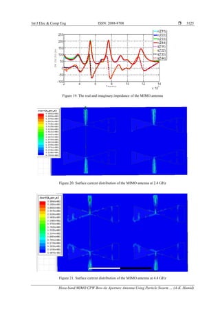
The following Figure 18 and Figure 19 Show the real and imaginary impedance for the original
unloaded antenna and the MIMO antenna respectively. It can be seen that the MIMO antenna is capable of
operating at six different frequency bands as the value of the real impedance is very close to 50 Ohms at the
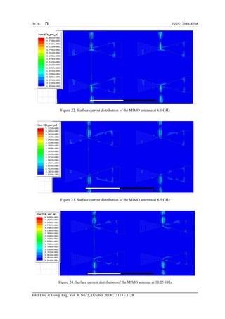
six operating frequency bands. The following results in Figures 20-25 show the MIMO antenna Surface
current distributions. It can be noticed that the current distribution is concentrated mostly at the center of
every MIMO antenna element in addition to the loaded metallic strips at the sides of each MIMO antenna
element.
Figure 18. The impedance for the original unloaded antenna [27]](https://image.slidesharecdn.com/v527sep1717jan188612-14889-1-ededitari-201118065637/85/Hexa-band-MIMO-CPW-Bow-tie-Aperture-Antenna-Using-Particle-Swarm-Optimization-7-320.jpg)
![Int J Elec & Comp Eng ISSN: 2088-8708
Hexa-band MIMO CPW Bow-tie Aperture Antenna Using Particle Swarm … (A-K. Hamid)
3127
Figure 25. Surface current distribution of the MIMO antenna at 12.8 GHz
The following Table 1 demonstrates comparison between the proposed MIMO bowtie antenna
design and other proposed MIMO antenna designs from the previous work. The proposed MIMO bowtie
antenna does not use extra components on the surface of the MIMO antenna to reduce the mutual coupling
between the MIMO antenna elements. The proposed MIMO antenna design has small surface area and low
surface structure complexity compared to most of other MIMO antenna designs in the previous work in
addition to more operational frequency bands compared to other MIMO antenna designs in the previous
work.
Table 1. Comparison between the Proposed MIMO Antenna Design and Other Proposed Designs
MIMO antenna
designs
Using extra
components to
reduce the mutual
coupling
MIMO Antenna
structure
complexity
MIMO Antenna
substrate
surface area
Operational frequency bands
The design in
[19]
no high large 2.25-2.26 GHz and 4.95-6 GHz
The design in
[22]
yes high 100x40
0.7 GHz,1.8 GHz,1.9 GHz, 2.3 GHz,2.5
GHz, and 2.4 GHz WLAN
The design in
[23]
yes high 142x90
1.8 GHz, 2.4 GHz, 3.5 GHz, 5.2 GHz,
and 5.5 GHz
The design in
[24]
yes high 270x210 1.8 GHz and 2.3 GHz
The design in
[25]
yes high n/a 1.8 GHz and 2.35 GHz
Our proposed
design
no Low 128x68
2.4 GHz, 4.4 GHz, 6.1 GHz, 8.5 GHz,
10.25 GHz, and 12.8 GHz
4. CONCLUSION
The simulated MIMO hexa-band bowtie antenna using HFSS was able to operate at six different
frequency bands: 2.4 GHz, 4.4 GHz, 6.1 GHz, 8.5 GHz, 10.25 GHz and 12.8 GHz. The width of the loaded
metallic strips on the surface of MIMO antenna elements was determined using Particle Swarm optimization
technique to be 1.66 mm and that resulted in a very low mutual coupling between every MIMO antenna
element at all the operating frequency bands. The MIMO antenna has an efficiency value above 90% at 2.4
GHz frequency and an efficiency value above 80% at the 4.4 GHz and 6.1 GHz frequency bands. It was
shown that the H-plane and E-plane are symmetric for the 2.4 GHz, 4.4 GHz, 6.1 GHz, and 8.5 GHz
frequency bands. The surface current distribution for each MIMO antenna element is concentrated mostly at
the center in addition to the loaded metallic strips.
ACKNOWLEDGEMENTS
We would like to acknowledge the support of University of Sharjah, United Arab Emirates.](https://image.slidesharecdn.com/v527sep1717jan188612-14889-1-ededitari-201118065637/85/Hexa-band-MIMO-CPW-Bow-tie-Aperture-Antenna-Using-Particle-Swarm-Optimization-10-320.jpg)
![ ISSN: 2088-8708
Int J Elec & Comp Eng, Vol. 8, No. 5, October 2018 : 3118 - 3128
3128
REFERENCES
[1] K. R. Mahmoud. “Design optimization of a bow-tie antenna for 2.45 GHz RFID readers using a hybrid BSO-NM
algorithm”. Progress In Electromagnetics Research. 100:105-17. 2010.
[2] M. H. Moradi, and M. Abedini “A combination of genetic algorithm and particle swarm optimization for optimal
DG location and sizing in distribution systems”. International Journal of Electrical Power & Energy Systems.
34(1):66-74. 2012.
[3] R. Poli, J. Kennedy, T. Blackwell “Particle swarm optimization”. Swarm intelligence. 1(1):33-57. 2007.
[4] L. Lizzi, F. Viani, R. Azaro, A. Massa “Optimization of a spline-shaped UWB antenna by PSO”. IEEE Antennas
and Wireless Propagation Letters. 6:182-5. 2007.
[5] J. Robinson, S. Sinton, Y. Rahmat-Samii “Particle swarm, genetic algorithm, and their hybrids: optimization of a
profiled corrugated horn antenna”. InAntennas and Propagation Society International Symposium. IEEE (Vol. 1, pp.
314-317). IEEE. 2002.
[6] J.-S. Chen, “Dual-frequency annular-ring slot antennas fed by CPW feed and microstrip line feed,” IEEE Trans.
Antennas Propag., vol. 53, no. 1, pp. 569–571, 2005.
[7] J.-S. Chen, “Triple-frequency annular-ring slot antennas fed by CPW and microstrip line,” in Proc. IEEE AP-S Int.
Symp., vol. 2, pp. 557–560, 2003
[8] J. H. Yoon and Y. C. Lee, “Modified bow-tie slot antenna for the 2.4/5.2/5.8 GHz WLAN bands with a rectangular
tuning stub,” Microw. Opt. Technol. Lett., vol. 52, no. 1, pp. 126–130, 2011.
[9] S.-Y. Chen, Y.-C. Chen, and P. Hsu, “CPW-fed aperture-coupled slot dipole antenna for tri-band operation,” IEEE
Antennas Wireless Propog. Lett., vol. 7, pp. 535–537, 2008.
[10] Y.-C. Chen, S.-Y. Chen, and P. Hsu, “A compact triband bow-tie slot antenna fed by a coplanar waveguide,” IEEE
Antennas Wireless Propog. Lett., vol. 9, pp. 1205–1208, 2010.
[11] W. Obaid and A-K. Hamid, “Simulation of CPW Bow-Tie Aperture Antenna Loaded With Metal Strips”, 16th
Mediterranean Microwave Symposium (MMS2016)”, Al Ain University of Science and Technology (AAU), in Abu
Dhabi City - United Arab Emirates (UAE), November 14th-16th, 2016.
[12] K. Singh, Y. Kumar, S. Singh “A modified bow tie antenna with U-shape slot for Wireless applications”.
International Journal of Emerging Technology and Advanced Engineering. 2(10):147-52. 2012.
[13] W. Obaid, A-K. Hamid, M. Abdul Samad “Multi-Frequency CPW Bow-Tie Aperture Antenna With Rectangular
and U Shape Metal Strips,” 5th International Conference on Electronic Devices, Systems, and Applications
(ICEDSA-2016), Ras Al Khaimah, UAE, 6-8 December, 2016.
[14] M. G. N. Alsath and M. Kanagasabai, “Planar pentaband antenna for vehicular communication application,” in IEEE
Antennas Wireless Propag. Lett., vol. 13, pp. 110–113. 2014.
[15] C. L. Tang, and C. M. Chiang, “Penta-band folded antenna for mobile phone application”. In Antennas and
Propagation Society International Symposium. AP-S 2008. IEEE (pp. 1-4). IEEE. 2008.
[16] J. G. Lee, D. J. Kim, and J. H. Lee, “Compact penta-band dual ZOR antenna for mobile applications”. International
Journal of Antennas and Propagation, 2016.
[17] B. Raj, G. S. Kartikeya, K. Ullas, S. N. Manjunath, and C. Vindhya, “A Miniaturized Metamaterial Inspired
Hexaband Antenna for GSM, GPS-L1, WLAN and WiMAX Applications”. Session 2P12 Small Antenna Design,
Analysis and Miniaturization Techniques, p.1117. 2015
[18] C.M. Peng, I. F. Chen, and C. T. Chien, “A novel hexa-band antenna for mobile handsets application”. IEEE
Transactions on Antennas and Propagation, 59(9), pp.3427-3432. 2011.
[19] W. C. Zheng, L. Zhang, Q. X. Li, Y. Zhou, & R. Rong, “Dual-band dual-polarized antenna array for beam selection
MIMO WLAN”. In Global Communications Conference (GLOBECOM), IEEE (pp. 4770-4774). IEEE. 2012.
[20] S. M. A. Nezhad, & H. R. Hassani “A novel triband E-shaped printed monopole antenna for MIMO application”
IEEE antennas and wireless propagation letters, 9, 576-579. 2010.
[21] R. A. Bhatti, J. H. Choi, & S. O. Park “Quad-band MIMO antenna array for portable wireless communications
terminals” IEEE antennas and wireless propagation letters, 8, 129-132. 2009.
[22] W. Huey Shin, S. Kibria, M. Tariqul Islam “Hexa band mimo antenna with neutralization line for LTE mobile
device application” Microwave and Optical Technology Letters. May 1;58(5):1198-204. 2016.
[23] I.M. Rafiqul, S. Rafiq, M.S. Yasmin and M.H. Habaebi “A 2X2 MIMO Patch Antenna for Multi-Band
Applications” Indonesian Journal of Electrical Engineering and Informatics (IJEEI), 5(4), pp.383-389. 2017.
[24] S. Pramono, T. Hariyadi, and B.B. Subagio “Performance of Groundplane Shaping in Four-Element Dualband
MIMO Antenna”. Telkomnika, 15(1). 2017.
[25] Y.K. Ningsih, and R. Hadinegoro “Low Mutual Coupling Dualband MIMO Microstrip Antenna with Air Gap
Parasitic”. TELKOMNIKA (Telecommunication Computing Electronics and Control), 12(2), pp.405-410. 2014.
[26] A. K. Hamid, & W. Obaid “Penta-frequency CPW bow-tie aperture antenna for mobile communications”. In
Modeling, Simulation, and Applied Optimization (ICMSAO), 7th International Conference on (pp. 1-4). IEEE.
(2017, April).
[27] Z. Guiping, A. Z. Elsherbeni, and C. E. Smith. "A coplanar waveguide bow-tie aperture antenna." Antennas and
Propagation Society International Symposium, Vol. 1. IEEE, 2002.](https://image.slidesharecdn.com/v527sep1717jan188612-14889-1-ededitari-201118065637/85/Hexa-band-MIMO-CPW-Bow-tie-Aperture-Antenna-Using-Particle-Swarm-Optimization-11-320.jpg)