The document discusses the design of a low-profile circular polarization folded reflectarray antenna for 5G applications, operating at a frequency of 28 GHz. The study shows that the proposed antenna achieves a directivity of 16.81 dB and an axial ratio of 1.49 dB, indicating excellent performance suitable for 5G wireless communication systems. The antenna's design incorporates components such as a meander lines polarizer, enhancing its performance compared to conventional linear polarization antennas.
![TELKOMNIKA, Vol.17, No.5, October 2019, pp.2250~2257
ISSN: 1693-6930, accredited First Grade by Kemenristekdikti, Decree No: 21/E/KPT/2018
DOI: 10.12928/TELKOMNIKA.v17i5.12812 ◼ 2250
Received October 25, 2018; Revised March 28, 2019; Accepted April 26, 2019
Circular polarization folded reflectarray antenna
for 5G applications
Mohd Fairus Mohd Yusoff*, Lim Jit Min, Mohamad Rijal Hamid,
Zaharah Johari, Muhammad Naeem Iqbal
School of Electrical Engineering, Universiti Teknologi Malaysia, 81310 UTM Skudai, Johor, Malaysia
*Corresponding author, e-mail: fairus@fke.utm.my
Abstract
Fifth-generation (5G) is a wireless connection built specifically to keep up with the rapid increase
of devices that need a mobile internet connection. A system working on 5G band can provide higher
bandwidth and faster data rate as compared to fourth-generation (4G) band. Thus, an antenna with higher
gain and lower profile is required to support this system. On the other hand, the performance of circular
polarization antenna is better than linear polarization antenna due to its ability to accept wave from
different direction. In this project, a low-profile circular polarization folded reflectarray antenna with
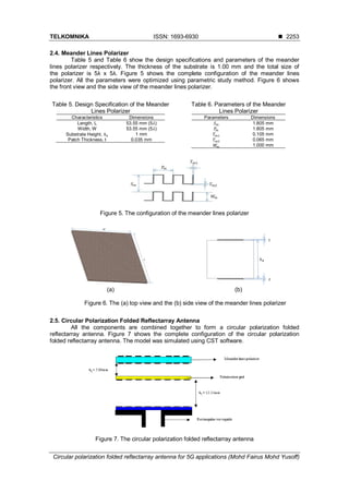
operating frequency of 28 GHz is presented. This project is divided into two parts. In the first part, a linear
polarization folded reflectarray antenna is designed. In this second part, a meander lines polarizer is used
to convert the linear polarization antenna to circular polarization antenna. The antenna is fed by a linear
polarized waveguide. Each radiating element of the antenna is in rectangular shape. The size of
the radiating elements are selected according to obtain required phase delay to form a planar phase front
in the far-field distance. Both of the antennas are simulated by using Computer Simulation Technology
(CST) software. Finally, the results show excellent performances with 16.81 dB directivity and 1.49 dB
axial ratio at 28 GHz. Thus, the antenna is very suitable for 5G applications.
Keywords: 5G wireless communication system, circular polarization, folded reflectarray antenna, meander
lines polarizer
Copyright © 2019 Universitas Ahmad Dahlan. All rights reserved.
1. Introduction
Fifth-generation (5G) wireless communication is expected to release by year 2020. As
compared to the current generation of wireless communication, 5G wireless communication has
significant improvement in term of the system performances [1-3]. According to International
Telecommunication Union (ITU), 5G wireless communication should be able to provide latency
on millisecond level, traffic volume density of 10 Tbps/km2
, connection density of 1 million per
square kilometer and so on [2-7]. Therefore, a suitable antenna with high gain, operating
frequency and bandwidth is required in order to provide these services [8-13].
In this case, a circular polarization folded reflectarray antenna that can offer bigger
bandwidth and higher gain compared to reflector and array antennas is proposed [12, 14-20].
The proposed antenna has reduced block effect and lower profile compared to reflectarray
antenna. On the other hand, circular polarization antenna has some advantages over linear
polarization antenna [21-24]. For instance, the circular polarization antenna is independent of
the direction of wave and it has lower rain attenuation than linear polarization antenna.
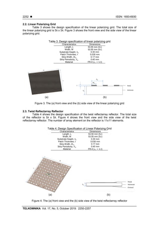
2. Design of Folded Reflectarray Antenna
Figure 1 shows the configuration of a circular polarization folded reflectarray antenna.
The antenna consists of four components, which are a primary source, a twist reflectarray
reflector, a linear polarizing grid and a linear to circular polarizer. In this project, a meander lines
polarizer is used to convert the antenna from linear polarization to circular polarization. Meander
lines polarizer had been used in many antenna designs, thus its performance is
guaranteed [25-32].
In general, a linear polarization incident wave propagates from the primary source to
the linear polarizing grid. Only the wave with E-field perpendicular to the strips of the linear
polarizing grid can passed through the grid, otherwise the wave reflects back to the twist](https://image.slidesharecdn.com/1512812-200813062756/85/Circular-polarization-folded-reflectarray-antenna-for-5G-applications-1-320.jpg)
![TELKOMNIKA ISSN: 1693-6930 ◼
Circular polarization folded reflectarray antenna for 5G applications (Mohd Fairus Mohd Yusoff)
2251
reflectarray reflector. The array elements on the twist reflectarray reflector twist the reflected
wave by 90°. Then, the wave reflects from the reflector to the grid. The wave can pass through
the grid now [17].
Table 1 shows the design specifications of the circular polarization folded reflectarray
antenna. Copper was used to design the waveguide, while FR-4 was used to design linear
polarizing grid, twist reflectarray reflector and meander lines polarizer. The dielectric constant of
FR-4 is 4.3.
Figure 1. The configuration of a circular polarization folded reflectarray antenna
Table 1. Design Specification of Folded Reflectarray Antenna
Parameters Specification
Operating frequency 28 GHz
Return loss < -10 dB
Dimension of reflector 5𝜆 x 5𝜆
Feeding method Rectangular waveguide
Array element Rectangular patch with variable
size
Array element spacing 0.455𝜆
Polarization Circular
Circular polarizer Meander lines polarizer
2.1. Primary Source
In this design, a rectangular open-ended waveguide WR-34 is used as shown
in Figure 2. The simulation of open-ended waveguide was carried out by using CST software.
Table 2 shows the technical specification of WR-34 waveguide.
Figure 2. WR-34 waveguide configuration
Table 2. Technical specification of
WR-34 waveguide
Model WR-34
Operating frequency 22-33 GHz
Length, 𝐿 𝑤𝑔 4.52 mm
Width, 𝑊𝑤𝑔 8.84 mm
Height, 𝐻 𝑤𝑔 32.13 mm (3𝜆)
Material Copper](https://image.slidesharecdn.com/1512812-200813062756/85/Circular-polarization-folded-reflectarray-antenna-for-5G-applications-2-320.jpg)
![◼ ISSN: 1693-6930
TELKOMNIKA Vol. 17, No. 5, October 2019: 2250-2257
2256
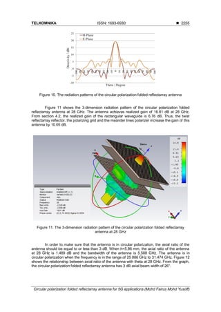
Figure 12. The axial ratio of circular polarization folded reflectarray antenna versus theta with
h=5.855 mm
4. Conclusion
A circular polarization folded reflectarray antenna with operating frequency of 28 GHz
was successfully designed and studied. The realized gain of the rectangular waveguide and
the circular polarization folded reflectarray antenna are 6.76 dB and 16.81 dB respectively.
The realized gain of the antenna is increased by 10.05 dB with present of a twist reflectarray
reflector, a linear polarizing grid and a meander lines polarizer. For the circular polarization,
the axial ratio is 1.489 dB at 28 GHz. This indicates that the antenna is in circular polarization at
this frequency. In addition, the antenna shows excellent performance with side lobe level below
-10 dB in both E-plane and H-plane. Therefore, the circular polarization folded reflectarray
antenna is suitable for 5G applications.
Acknowledgements
The authors would like to thank the Ministry of Higher Education (MOHE), Research
Management Centre (RMC), School of Electrical Engineering, Universiti Teknologi Malaysia
(UTM) for supporting the research work, under grant no. 14J22.
References
[1] Andrews JG, Buzzi S, Choi W, Hanly SV, Lozano A, Soong AC, et al. What will 5G be? IEEE Journal
on selected areas in communications. 2014; 32: 1065-1082.
[2] Wang C-X, Haider F, Gao X, You X-H, Yang Y, Yuan D, et al. Cellular architecture and key
technologies for 5G wireless communication networks. IEEE communications magazine. 2014; 52:
122-130.
[3] Yang N, Wang L, Geraci G, Elkashlan M, Yuan J, Di Renzo M. Safeguarding 5G wireless
communication networks using physical layer security. IEEE Communications Magazine. 2015; 53:
20-27.
[4] Demestichas P, Georgakopoulos A, Karvounas D, Tsagkaris K, Stavroulaki V, Lu J, et al. 5G on the
horizon: Key challenges for the radio-access network. IEEE vehicular technology magazine. 2013; 8:
47-53.
[5] Rappaport TS, Sun S, Mayzus R, Zhao H, Azar Y, Wang K, et al. Millimeter wave mobile
communications for 5G cellular: It will work! IEEE access. 2013; 1: 335-349.
[6] Chen S, Zhao J. The requirements, challenges, and technologies for 5G of terrestrial mobile
telecommunication. IEEE communications magazine. 2014; 52: 36-43.
[7] Roh W, Seol JY, Park J, Lee B, Lee J, Kim Y, et al. Millimeter-wave beamforming as an enabling
technology for 5G cellular communications: Theoretical feasibility and prototype results. IEEE
communications magazine. 2014; 52: 106-113.
[8] Hong W, Baek K-H, Lee Y, Kim Y, Ko S-T. Study and prototyping of practically large-scale mmWave
antenna systems for 5G cellular devices. IEEE Communications Magazine. 2014; 52: 63-69.
[9] Han S, Chih-Lin I, Xu Z, Rowell C. Large-scale antenna systems with hybrid analog and digital
beamforming for millimeter wave 5G. IEEE Communications Magazine. 2015; 53: 186-94.
[10] Ojaroudiparchin N, Shen M, Fr G. Multi-layer 5G mobile phone antenna for multi-user MIMO
communications. 2015 23rd
Telecommunications Forum Telfor (TELFOR): IEEE. 2015: 559-62.
[11] Ban Y-L, Li C, Wu G, Wong K-L. 4G/5G multiple antennas for future multi-mode smartphone
applications. IEEE access. 2016; 4: 2981-2988.](https://image.slidesharecdn.com/1512812-200813062756/85/Circular-polarization-folded-reflectarray-antenna-for-5G-applications-7-320.jpg)
![TELKOMNIKA ISSN: 1693-6930 ◼
Circular polarization folded reflectarray antenna for 5G applications (Mohd Fairus Mohd Yusoff)
2257
[12] Shen Y, Hu S, Dou W. 38 GHz folded reflectarray antenna for point-to-point 5G communications.
2016 IEEE 5th
Asia-Pacific Conference on Antennas and Propagation (APCAP): IEEE. 2016: 369-70.
[13] Hong W, Jiang ZH, Yu C, Zhou J, Chen P, Yu Z, et al. Multibeam antenna technologies for 5G
wireless communications. IEEE Transactions on Antennas and Propagation. 2017; 65: 6231-6249.
[14] Pilz D, Menzel W. Folded reflectarray antenna. Electronics Letters. 1998; 34: 832-833.
[15] Menzel W, Pilz D, Al-Tikriti M. Millimeter-wave folded reflector antennas with high gain, low loss, and
low profile. IEEE Antennas and Propagation magazine. 2002; 44: 24-29.
[16] Zornoza JA, Leberer R, Encinar JA, Menzel W. Folded multilayer microstrip reflectarray with shaped
pattern. IEEE Transactions on Antennas and Propagation. 2006; 54: 510-518.
[17] Yusoff MFM, Sauleau R, Hamid MR, Rahim M, Yusoff M. Beam scanning folded reflectarray antenna
with shifted waveguide positions. 2013 IEEE International RF and Microwave Conference (RFM):
IEEE. 2013: 193-196.
[18] Jiang M, Hong W, Zhang Y, Yu S, Zhou H. A folded reflectarray antenna with a planar SIW slot array
antenna as the primary source. IEEE Transactions on Antennas and Propagation. 2014; 62: 3575-83.
[19] Liu X, Ge Y, Chen X, Chen L. Design of folded reflectarray antennas using pancharatnam-berry
phase reflectors. IEEE Access. 2018; 6: 28818-28824.
[20] Yang J, Shen Y, Wang L, Meng H, Dou W, Hu S. 2-D scannable 40-GHz folded reflectarray fed by
SIW slot antenna in single-layered PCB. IEEE Transactions on Microwave Theory and Techniques.
2018; 66: 3129-3135.
[21] Pett TA, Olson SC, Sreenivas AI. Broadband circular polarization antenna. Google Patents. 1995.
[22] Yang F, Rahmat-Samii Y. A reconfigurable patch antenna using switchable slots for circular
polarization diversity. IEEE Microwave and Wireless Components Letters. 2002; 12: 96-98.
[23] Toh BY, Cahill R, Fusco VF. Understanding and measuring circular polarization. IEEE Transactions
on Education. 2003; 46: 313-318.
[24] Wu F, Luk KM. Circular Polarization and Reconfigurability of Fabry-Perot Resonator Antenna through
Metamaterial-Loaded Cavity. IEEE Transactions on Antennas and Propagation. 2019.
[25] Young L, Robinson L, Hacking C. Meander-line polarizer. IEEE Transactions on Antennas and
Propagation. 1973; 21: 376-378.
[26] Chu R-S, Lee K-M. Analytical method of a multilayered meander-line polarizer plate with normal and
oblique plane-wave incidence. IEEE Transactions on Antennas and Propagation. 1987; 35: 652-661.
[27] Wu T-K. Meander-line polarizer for arbitrary rotation of linear polarization. IEEE microwave and
guided wave letters. 1994; 4: 199-201.
[28] Mazur M, Zieniutycz W. Multi-layer meander line polarizer for Ku band. 13th
International Conference
on Microwaves, Radar and Wireless Communications MIKON-2000 Conference Proceedings (IEEE
Cat No 00EX428): IEEE. 2000: 78-81.
[29] Joyal M-A, Riel M, Demers Y, Laurin J-J. A meander-line circular polarizer optimized for oblique
incidence. IEEE Transactions on Antennas and Propagation. 2015; 63: 5391-5398.
[30] Stankovsky A, Polenga S, Nemshon A, Litinskaya Y, Gafarov E, Salomatov YP. Meander-line
polarizer for omnidirectional antenna. 2016 International Siberian Conference on Control and
Communications (SIBCON): IEEE. 2016: 1-4.
[31] Fei P, Guo W, Wen X. A Low Profile Meander Line Circular Polarizer for Wideband Applications.
2018 International Conference on Microwave and Millimeter Wave Technology (ICMMT): IEEE. 2018:
1-3.
[32] Nakajima H, Tanaka T, Takikawa M, Yoneda N. A Study of Meander Line Polarizer Based on
Equivalent Circuits. 2018 IEEE International Workshop on Electromagnetics: Applications and
Student Innovation Competition (iWEM): IEEE. 2018.](https://image.slidesharecdn.com/1512812-200813062756/85/Circular-polarization-folded-reflectarray-antenna-for-5G-applications-8-320.jpg)