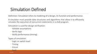
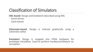
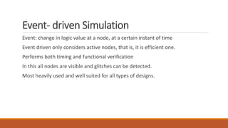
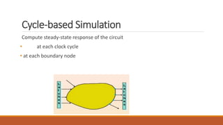
HDL BASED
SIMULATORS
PRACHI PANDEY
Simulation Defined
Definition: Simulation refers to modeling of a design, its function and performance.
A simulator must provide data structures and algorithms that allow it to efficiently
simulate the execution of concurrent statements in a vhdl program.
Simulation is used for design verification:
◦ Validate assumptions
◦ Verify logic
◦ Verify performance (timing)
Types of simulation:
◦ Logic or switch level
◦ Timing
◦ Circuit
◦ Fault
3/17/2017 2
Classification of Simulators
HDL-based: Design and testbench described using HDL
◦ Event-driven
◦ Cycle-based
Schematic-based: Design is entered graphically using a
schematic editor
Emulators: Design is mapped into FPGA hardware for
prototype simulation. Used to perform hardware/software co-
simulation.
Event- driven Simulation
Event: change in logic value at a node, at a certain instant of time
Event driven only considers active nodes, that is, it is efficient one.
Performs both timing and functional verification
In this all nodes are visible and glitches can be detected.
Most heavily used and well suited for all types of designs.
Event-Driven Logic Simulation
Evaluate gate when inputs change
◦ use logic model to compute new output value
◦ use timing model to compute when output will change
Schedule an output change event
◦ store the event on a time-sorted event queue
Process events from the queue
◦ output change evaluated at scheduled time
◦ causes new events to be scheduled
5
5
7
5
5
5
0
0
0
1->0
(0)
0
1
1
1
0->1
(5)
1->0
(12)
1->0
(10)
Steps in an Event Driven Simulation
The LRM(Language Reference Manual) defines how an event-driven
simulator must execute the VHDL.
Simulator vendors implement this concepts.
An event-driven simulator performs three steps to accomplish a
simulation:
Elaboration
Initialization
Repeated execution of simulation cycles
Elaboration
Elaboration is the creation of a simulation model for a design entity
from its VHDL description. This simulation model consists of a net of
simulation process.
During elaboration, all concurrent statements are converted to
equivalent simulation processes.
Initialization
At the beginning of initialization, the current time is 0 ns
The effective value of each explicitly declared signal are computed,
and the current value of the signal is set to the effective value.
Each process is executed until it suspends.
The time of the next simulation cycle is calculated according to the
rules of the simulation cycle
Cycle-based Simulation
Compute steady-state response of the circuit
• at each clock cycle
• at each boundary node
Cycle Simulation
Cycle simulation is a technique for simulating circuits that do not take into
account the detailed circuit timing
Cycle simulation computes the steady state response of the circuit at each clock
cycle boundary
Need for another tool for timing analysis
Cycle Simulation Techniques
Event ordering and delayed evaluation
◦ All scheduled evaluations will take place at active edge of clock
◦ All events are put in an event orderer which eliminate unnecessary
evaluations
Cycle Simulation Techniques
Cycle based oblivious simulation
◦ Logic levelization is applied to the design
◦ Clocked elements are clocked at active edge
◦ Combinational logic is evaluated during the cycle
Cycle Simulation Specifications
Ignore timing and reducing the state set(2 value and sometime 4 value)
• Efficient evaluation and faster simulation
Circuit levelization at compile time
• Each element is evaluated once during clock cycle
Simple data structure for simulator
10 to 100 times performance over event driven simulation
Areas of Applicability
Large synthesizable or logic optimizable designs
Designs that are mostly synchronous
Designs meet the cycle simulation subset
◦ RTL regression
◦ Gate-level verification
THANK YOU

Hdl based simulators

  • 1.
  • 2.
    Simulation Defined Definition: Simulationrefers to modeling of a design, its function and performance. A simulator must provide data structures and algorithms that allow it to efficiently simulate the execution of concurrent statements in a vhdl program. Simulation is used for design verification: ◦ Validate assumptions ◦ Verify logic ◦ Verify performance (timing) Types of simulation: ◦ Logic or switch level ◦ Timing ◦ Circuit ◦ Fault 3/17/2017 2
  • 3.
    Classification of Simulators HDL-based:Design and testbench described using HDL ◦ Event-driven ◦ Cycle-based Schematic-based: Design is entered graphically using a schematic editor Emulators: Design is mapped into FPGA hardware for prototype simulation. Used to perform hardware/software co- simulation.
  • 4.
    Event- driven Simulation Event:change in logic value at a node, at a certain instant of time Event driven only considers active nodes, that is, it is efficient one. Performs both timing and functional verification In this all nodes are visible and glitches can be detected. Most heavily used and well suited for all types of designs.
  • 5.
    Event-Driven Logic Simulation Evaluategate when inputs change ◦ use logic model to compute new output value ◦ use timing model to compute when output will change Schedule an output change event ◦ store the event on a time-sorted event queue Process events from the queue ◦ output change evaluated at scheduled time ◦ causes new events to be scheduled 5 5 7 5 5 5 0 0 0 1->0 (0) 0 1 1 1 0->1 (5) 1->0 (12) 1->0 (10)
  • 7.
    Steps in anEvent Driven Simulation The LRM(Language Reference Manual) defines how an event-driven simulator must execute the VHDL. Simulator vendors implement this concepts. An event-driven simulator performs three steps to accomplish a simulation: Elaboration Initialization Repeated execution of simulation cycles
  • 8.
    Elaboration Elaboration is thecreation of a simulation model for a design entity from its VHDL description. This simulation model consists of a net of simulation process. During elaboration, all concurrent statements are converted to equivalent simulation processes.
  • 9.
    Initialization At the beginningof initialization, the current time is 0 ns The effective value of each explicitly declared signal are computed, and the current value of the signal is set to the effective value. Each process is executed until it suspends. The time of the next simulation cycle is calculated according to the rules of the simulation cycle
  • 10.
    Cycle-based Simulation Compute steady-stateresponse of the circuit • at each clock cycle • at each boundary node
  • 11.
    Cycle Simulation Cycle simulationis a technique for simulating circuits that do not take into account the detailed circuit timing Cycle simulation computes the steady state response of the circuit at each clock cycle boundary Need for another tool for timing analysis
  • 12.
    Cycle Simulation Techniques Eventordering and delayed evaluation ◦ All scheduled evaluations will take place at active edge of clock ◦ All events are put in an event orderer which eliminate unnecessary evaluations
  • 13.
    Cycle Simulation Techniques Cyclebased oblivious simulation ◦ Logic levelization is applied to the design ◦ Clocked elements are clocked at active edge ◦ Combinational logic is evaluated during the cycle
  • 14.
    Cycle Simulation Specifications Ignoretiming and reducing the state set(2 value and sometime 4 value) • Efficient evaluation and faster simulation Circuit levelization at compile time • Each element is evaluated once during clock cycle Simple data structure for simulator 10 to 100 times performance over event driven simulation
  • 15.
    Areas of Applicability Largesynthesizable or logic optimizable designs Designs that are mostly synchronous Designs meet the cycle simulation subset ◦ RTL regression ◦ Gate-level verification
  • 16.