Downloaded 11 times


1. The document discusses modeling and simulation of computer networks. It covers discrete-event simulation, tools for network simulation like ns-3, and modeling different layers and elements of the network. 2. It also discusses simulation frameworks, modeling approaches for hardware simulation using instruction set simulation, and tools for network simulation like openWNS which can simulate WiFi, WiMAX and other protocol stacks. 3. The core algorithms of discrete event simulation involve modeling the system state, clock, future event list, and using event routines to process events and update the state.


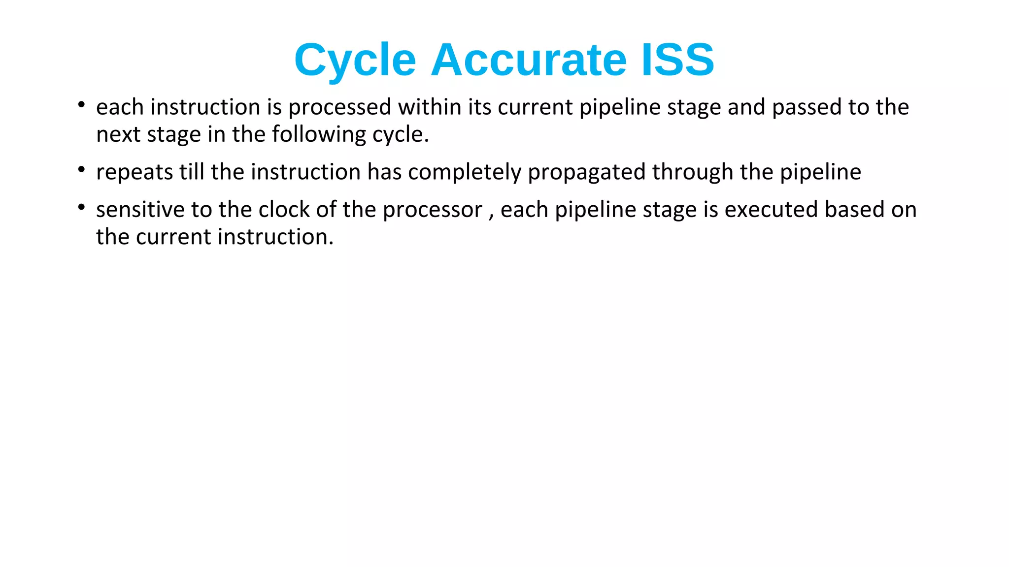
![[EUC2016] FFWD: latency-aware event stream processing via domain-specific loa...](https://cdn.slidesharecdn.com/ss_thumbnails/ffwd-171206183549-thumbnail.jpg?width=640&height=640&fit=bounds)