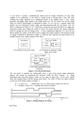
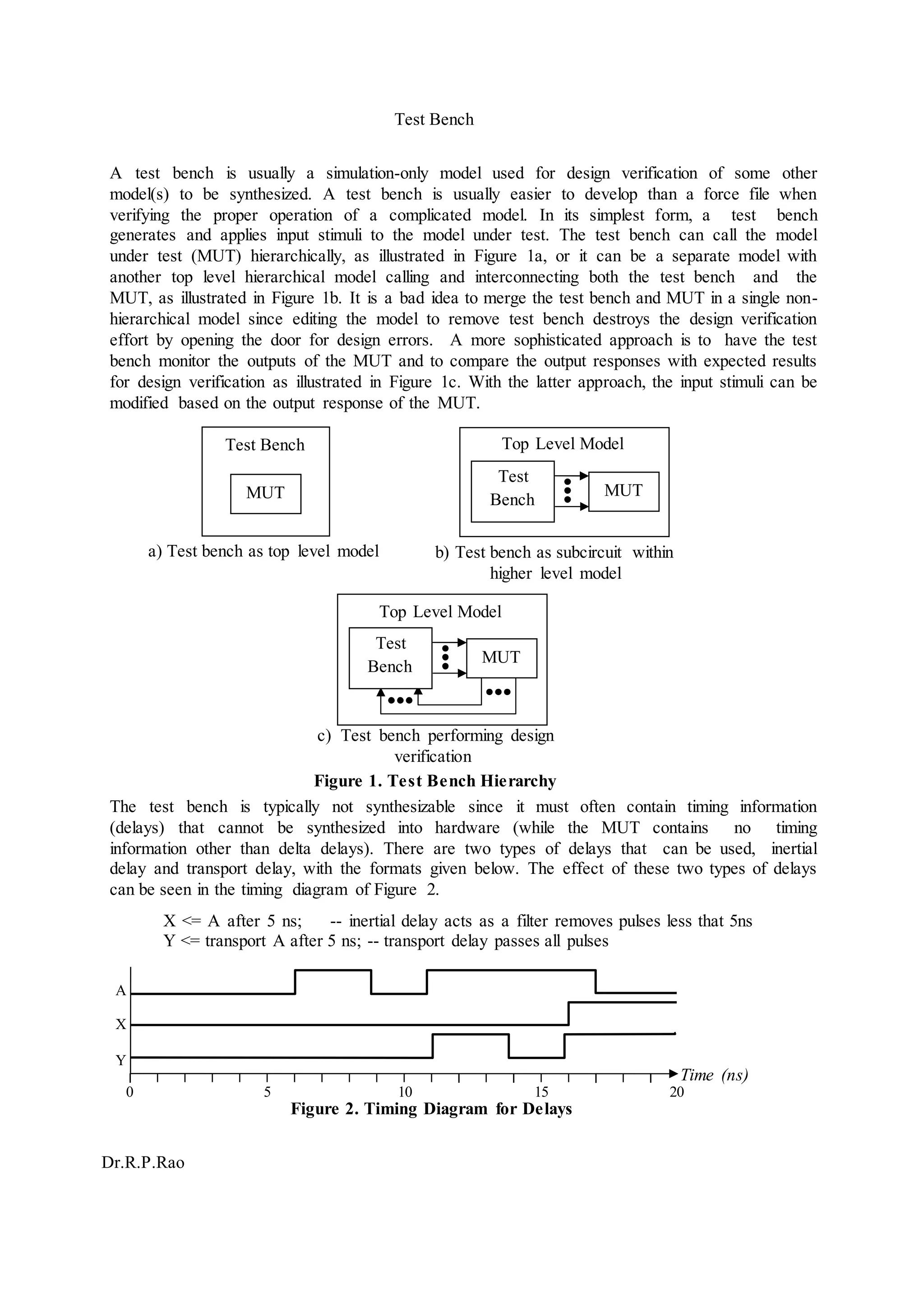
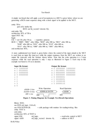
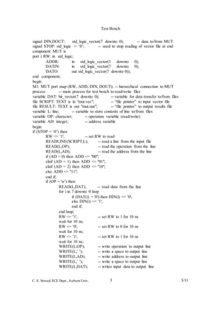
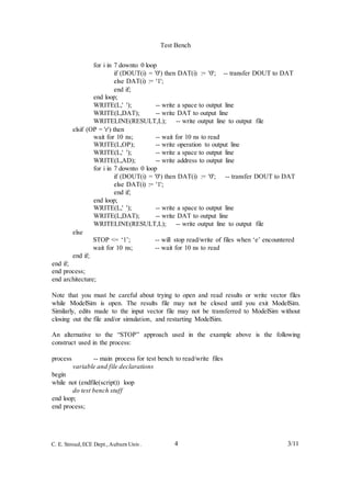
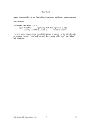
Test Bench
Dr.R.P.Rao
Test Bench Top Level Model
MUT
Test
Bench
Top Level Model
MUT
Test
Bench
A test bench is usually a simulation-only model used for design verification of some other
model(s) to be synthesized. A test bench is usually easier to develop than a force file when
verifying the proper operation of a complicated model. In its simplest form, a test bench
generates and applies input stimuli to the model under test. The test bench can call the model
under test (MUT) hierarchically, as illustrated in Figure 1a, or it can be a separate model with
another top level hierarchical model calling and interconnecting both the test bench and the
MUT, as illustrated in Figure 1b. It is a bad idea to merge the test bench and MUT in a single non-
hierarchical model since editing the model to remove test bench destroys the design verification
effort by opening the door for design errors. A more sophisticated approach is to have the test
bench monitor the outputs of the MUT and to compare the output responses with expected results
for design verification as illustrated in Figure 1c. With the latter approach, the input stimuli can be
modified based on the output response of the MUT.
a) Test bench as top level model b) Test bench as subcircuit within
higher level model
c) Test bench performing design
verification
Figure 1. Test Bench Hierarchy
The test bench is typically not synthesizable since it must often contain timing information
(delays) that cannot be synthesized into hardware (while the MUT contains no timing
information other than delta delays). There are two types of delays that can be used, inertial
delay and transport delay, with the formats given below. The effect of these two types of delays
can be seen in the timing diagram of Figure 2.
X <= A after 5 ns; -- inertial delay acts as a filter removes pulses less that 5ns
Y <= transport A after 5 ns; -- transport delay passes all pulses
A
X
Y
Time (ns)
0 5 10 15 20
Figure 2. Timing Diagram for Delays
MUT
Test Bench
Dr.R.P.Rao
A simple test bench that will apply a set of test patterns to a MUT is given below where we are
generating a BCD count sequence along with a clock signal to be applied to the MUT:
entity TB is
port (CK: buffer bit;
BCD: out bit_vector(3 downto 0));
end entity TB;
architecture RTL of TB is
signal INIT: bit;
begin
CK <= not CK after 50 ns; -- repetitive patterns
BCD <= “0000”, “0001” after 100ns, “0010” after 200 ns, “0011” after 300 ns,
“0100” after 400 ns, “0101” after 500 ns, “0110” after 600 ns,
“0111” after 700 ns, “1000” after 800 ns, “1001” after 900 ns;
end architecture RTL;
A more sophisticated test bench is given below where the control of the input stimuli to the MUT
is read from an input file (mut.vec) while the output responses from the MUT are written to an
output file (mut.out) with the formats shown below. Note that the write operation is a 3-step
sequence while the read operation is only 1 step as illustrated in Figure 3. Each step in this
example test bench is 10 ns in duration.
Input file format:
w 0 10000000
w 1 00100001
w 2 00000000
w 3 00000000
r 0
r 1
r 2
r 3
e 0
Output file format:
w 0 10000000 10000000
w 1 00100001 00100001
w 2 00000000 00000000
w 3 00000000 00000000
r 0 00000001
r 1 00100001
r 2 10100100
r 3 00000110
ADDR=2-bits
DATIN=8-bits
RW=1-bit
Write Operation Read Operation
RW
Figure 3. Timing Diagram for Example Test Bench Operations
library IEEE;
use IEEE.std_logic_1164.all;
use STD.TEXTIO.all; -- calls package with routines for reading/writing files
entity TEST is
end entity;
architecture RTL of TEST is
signal RW: std_logic; -- read/write control to MUT
signal ADD: std_logic_vector(1 downto 0); -- address to MUT
ADDRADDR & DATIN
RW
Test Bench
3 3/11C. E. Stroud,ECE Dept.,Auburn Univ.
signal DIN,DOUT: std_logic_vector(7 downto 0); -- data to/from MUT
signal STOP: std_logic := ‘0’; -- used to stop reading of vector file at end
component MUT is
port ( RW: in std_logic;
ADDR: in std_logic_vector(1 downto 0);
DATIN: in std_logic_vector(7 downto 0);
DATO: out std_logic_vector(7 downto 0));
end component;
begin
M1: MUT port map (RW, ADD, DIN, DOUT); -- hierarchical connection to MUT
process -- main process for test bench to read/write files
variable DAT: bit_vector(7 downto 0); -- variable for data transfer to/from files
file SCRIPT: TEXT is in "mut.vec"; -- “file pointer” to input vector file
file RESULT: TEXT is out "mut.out"; -- “file pointer” to output results file
variable L: line; -- variable to store contents of line to/from files
variable OP: character; -- operation variable (read/write)
variable AD: integer; -- address variable
begin
if (STOP = ‘0’) then
RW <= '1'; -- set RW to read
READLINE(SCRIPT,L); -- read a line from the input file
READ(L,OP); -- read the operation from the line
READ(L,AD); -- read the address from the line
if (AD = 0) then ADD <= "00";
elsif (AD = 1) then ADD <= "01";
elsif (AD = 2) then ADD <= "10";
else ADD <= "11";
end if;
if (OP = 'w') then
READ(L,DAT); -- read data from the line
for i in 7 downto 0 loop
if (DAT(i) = '0') then DIN(i) <= '0';
else DIN(i) <= '1';
end if;
end loop;
RW <= '1'; -- set RW to 1 for 10 ns
wait for 10 ns;
RW <= '0'; -- set RW to 0 for 10 ns
wait for 10 ns;
RW <= '1'; -- set RW to 1 for 10 ns
wait for 10 ns;
WRITE(L,OP); -- write operation to output line
WRITE(L,' '); -- write a space to output line
WRITE(L,AD); -- write address to output line
WRITE(L,' '); -- write a space to output line
WRITE(L,DAT); -- writes input data to output line
Test Bench
4 3/11C. E. Stroud,ECE Dept.,Auburn Univ.
for i in 7 downto 0 loop
if (DOUT(i) = '0') then DAT(i) := '0'; -- transfer DOUT to DAT
else DAT(i) := '1';
end if;
end loop;
WRITE(L,' '); -- write a space to output line
WRITE(L,DAT); -- write DAT to output line
WRITELINE(RESULT,L); -- write output line to output file
elsif (OP = 'r') then
wait for 10 ns; -- wait for 10 ns to read
WRITE(L,OP); -- write operation to output line
WRITE(L,' '); -- write a space to output line
WRITE(L,AD); -- write address to output line
for i in 7 downto 0 loop
if (DOUT(i) = '0') then DAT(i) := '0'; -- transfer DOUT to DAT
else DAT(i) := '1';
end if;
end loop;
WRITE(L,' '); -- write a space to output line
WRITE(L,DAT); -- write DAT to output line
WRITELINE(RESULT,L); -- write output line to output file
end if;
else
end if;
STOP <= ‘1’; -- will stop read/write of files when ‘e’ encountered
wait for 10 ns; -- wait for 10 ns to read
end process;
end architecture;
Note that you must be careful about trying to open and read results or write vector files
while ModelSim is open. The results file may not be closed until you exit ModelSim.
Similarly, edits made to the input vector file may not be transferred to ModelSim without
closing out the file and/or simulation, and restarting ModelSim.
An alternative to the “STOP” approach used in the example above is the following
construct used in the process:
process -- main process for test bench to read/write files
variable and file declarations
begin
while not (endfile(script)) loop
do test bench stuff
end loop;
end process;
Test Bench
5 3/11C. E. Stroud,ECE Dept.,Auburn Univ.
assert statements check to see if a condition is true or not and displays an error message
general format:
assert BOOLEAN-EXPRESSION
report “STRING” -- reports only if Boolean-expression is false
severity SEVERITY-LEVEL ; -- severity is optional
3 severity-levels: note, warning, error, failure (lowest to highest) –action taken depends
on simulator (typically “note” and “warning” keep running while “error” and “failure”
halt simulation)

Hd9

  • 1.
    Test Bench Dr.R.P.Rao Test BenchTop Level Model MUT Test Bench Top Level Model MUT Test Bench A test bench is usually a simulation-only model used for design verification of some other model(s) to be synthesized. A test bench is usually easier to develop than a force file when verifying the proper operation of a complicated model. In its simplest form, a test bench generates and applies input stimuli to the model under test. The test bench can call the model under test (MUT) hierarchically, as illustrated in Figure 1a, or it can be a separate model with another top level hierarchical model calling and interconnecting both the test bench and the MUT, as illustrated in Figure 1b. It is a bad idea to merge the test bench and MUT in a single non- hierarchical model since editing the model to remove test bench destroys the design verification effort by opening the door for design errors. A more sophisticated approach is to have the test bench monitor the outputs of the MUT and to compare the output responses with expected results for design verification as illustrated in Figure 1c. With the latter approach, the input stimuli can be modified based on the output response of the MUT. a) Test bench as top level model b) Test bench as subcircuit within higher level model c) Test bench performing design verification Figure 1. Test Bench Hierarchy The test bench is typically not synthesizable since it must often contain timing information (delays) that cannot be synthesized into hardware (while the MUT contains no timing information other than delta delays). There are two types of delays that can be used, inertial delay and transport delay, with the formats given below. The effect of these two types of delays can be seen in the timing diagram of Figure 2. X <= A after 5 ns; -- inertial delay acts as a filter removes pulses less that 5ns Y <= transport A after 5 ns; -- transport delay passes all pulses A X Y Time (ns) 0 5 10 15 20 Figure 2. Timing Diagram for Delays MUT
  • 2.
    Test Bench Dr.R.P.Rao A simpletest bench that will apply a set of test patterns to a MUT is given below where we are generating a BCD count sequence along with a clock signal to be applied to the MUT: entity TB is port (CK: buffer bit; BCD: out bit_vector(3 downto 0)); end entity TB; architecture RTL of TB is signal INIT: bit; begin CK <= not CK after 50 ns; -- repetitive patterns BCD <= “0000”, “0001” after 100ns, “0010” after 200 ns, “0011” after 300 ns, “0100” after 400 ns, “0101” after 500 ns, “0110” after 600 ns, “0111” after 700 ns, “1000” after 800 ns, “1001” after 900 ns; end architecture RTL; A more sophisticated test bench is given below where the control of the input stimuli to the MUT is read from an input file (mut.vec) while the output responses from the MUT are written to an output file (mut.out) with the formats shown below. Note that the write operation is a 3-step sequence while the read operation is only 1 step as illustrated in Figure 3. Each step in this example test bench is 10 ns in duration. Input file format: w 0 10000000 w 1 00100001 w 2 00000000 w 3 00000000 r 0 r 1 r 2 r 3 e 0 Output file format: w 0 10000000 10000000 w 1 00100001 00100001 w 2 00000000 00000000 w 3 00000000 00000000 r 0 00000001 r 1 00100001 r 2 10100100 r 3 00000110 ADDR=2-bits DATIN=8-bits RW=1-bit Write Operation Read Operation RW Figure 3. Timing Diagram for Example Test Bench Operations library IEEE; use IEEE.std_logic_1164.all; use STD.TEXTIO.all; -- calls package with routines for reading/writing files entity TEST is end entity; architecture RTL of TEST is signal RW: std_logic; -- read/write control to MUT signal ADD: std_logic_vector(1 downto 0); -- address to MUT ADDRADDR & DATIN RW
  • 3.
    Test Bench 3 3/11C.E. Stroud,ECE Dept.,Auburn Univ. signal DIN,DOUT: std_logic_vector(7 downto 0); -- data to/from MUT signal STOP: std_logic := ‘0’; -- used to stop reading of vector file at end component MUT is port ( RW: in std_logic; ADDR: in std_logic_vector(1 downto 0); DATIN: in std_logic_vector(7 downto 0); DATO: out std_logic_vector(7 downto 0)); end component; begin M1: MUT port map (RW, ADD, DIN, DOUT); -- hierarchical connection to MUT process -- main process for test bench to read/write files variable DAT: bit_vector(7 downto 0); -- variable for data transfer to/from files file SCRIPT: TEXT is in "mut.vec"; -- “file pointer” to input vector file file RESULT: TEXT is out "mut.out"; -- “file pointer” to output results file variable L: line; -- variable to store contents of line to/from files variable OP: character; -- operation variable (read/write) variable AD: integer; -- address variable begin if (STOP = ‘0’) then RW <= '1'; -- set RW to read READLINE(SCRIPT,L); -- read a line from the input file READ(L,OP); -- read the operation from the line READ(L,AD); -- read the address from the line if (AD = 0) then ADD <= "00"; elsif (AD = 1) then ADD <= "01"; elsif (AD = 2) then ADD <= "10"; else ADD <= "11"; end if; if (OP = 'w') then READ(L,DAT); -- read data from the line for i in 7 downto 0 loop if (DAT(i) = '0') then DIN(i) <= '0'; else DIN(i) <= '1'; end if; end loop; RW <= '1'; -- set RW to 1 for 10 ns wait for 10 ns; RW <= '0'; -- set RW to 0 for 10 ns wait for 10 ns; RW <= '1'; -- set RW to 1 for 10 ns wait for 10 ns; WRITE(L,OP); -- write operation to output line WRITE(L,' '); -- write a space to output line WRITE(L,AD); -- write address to output line WRITE(L,' '); -- write a space to output line WRITE(L,DAT); -- writes input data to output line
  • 4.
    Test Bench 4 3/11C.E. Stroud,ECE Dept.,Auburn Univ. for i in 7 downto 0 loop if (DOUT(i) = '0') then DAT(i) := '0'; -- transfer DOUT to DAT else DAT(i) := '1'; end if; end loop; WRITE(L,' '); -- write a space to output line WRITE(L,DAT); -- write DAT to output line WRITELINE(RESULT,L); -- write output line to output file elsif (OP = 'r') then wait for 10 ns; -- wait for 10 ns to read WRITE(L,OP); -- write operation to output line WRITE(L,' '); -- write a space to output line WRITE(L,AD); -- write address to output line for i in 7 downto 0 loop if (DOUT(i) = '0') then DAT(i) := '0'; -- transfer DOUT to DAT else DAT(i) := '1'; end if; end loop; WRITE(L,' '); -- write a space to output line WRITE(L,DAT); -- write DAT to output line WRITELINE(RESULT,L); -- write output line to output file end if; else end if; STOP <= ‘1’; -- will stop read/write of files when ‘e’ encountered wait for 10 ns; -- wait for 10 ns to read end process; end architecture; Note that you must be careful about trying to open and read results or write vector files while ModelSim is open. The results file may not be closed until you exit ModelSim. Similarly, edits made to the input vector file may not be transferred to ModelSim without closing out the file and/or simulation, and restarting ModelSim. An alternative to the “STOP” approach used in the example above is the following construct used in the process: process -- main process for test bench to read/write files variable and file declarations begin while not (endfile(script)) loop do test bench stuff end loop; end process;
  • 5.
    Test Bench 5 3/11C.E. Stroud,ECE Dept.,Auburn Univ. assert statements check to see if a condition is true or not and displays an error message general format: assert BOOLEAN-EXPRESSION report “STRING” -- reports only if Boolean-expression is false severity SEVERITY-LEVEL ; -- severity is optional 3 severity-levels: note, warning, error, failure (lowest to highest) –action taken depends on simulator (typically “note” and “warning” keep running while “error” and “failure” halt simulation)