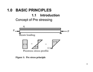
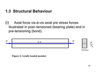
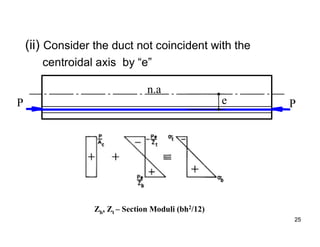
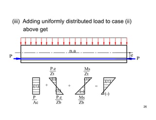
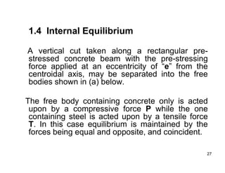
1
1
UNIVERSITY OF DAR ES SALAAM
SC 442
FUNDAMENTALS OF PRE STRESSED CONCRETE
DESIGN
(c) Dr Daudi S. Augustino
2023
References
• Hurst, M.K (1998). Prestressed concrete
design,2nd edition.
• Marshall, V & Robberts J.M. Prestressed
concrete design and practice. Concrete
society of Southern Africa pressed concrete
division Midrand, South Africa.
2
3
3
1.0 BASIC PRINCIPLES
1.1 Introduction
Concept of Pre stressing
(+)
(+)
(-)
+
(+)
(-)
=
P
P
q
Beam loading
Prestress stress profile
Figure 1: Pre stress principle
4
Introduction
The idea of prestressed concrete has been around since the
latter decades of the 19th century, but its use was limited by
the quality of the materials at the time. It took until the 1920s
and ‘30s for its materials development to progress to a level
where prestressed concrete could be used with confidence.
Freyssinet in France, Magnel in Belgium and Hoyer in
Germany were the principle developers
5
5
Essential Features
- High strength steel
- Loss of prestressing force due for concrete
shrinkage and creep and steel relaxation
- Quality (strength) of concrete
- Strong anchorages
6
Uses of Prestressed Concrete
There are a huge number of uses:
•Railway Sleepers;
•Communications poles;
•Pre-tensioned precast “hollow core” slabs;
•Pre-tensioned Precast Double T units - for very
long spans (e.g., 16 m span for car parks);
•Pre-tensioned precast inverted T beam for
short- span bridges;
•Pre-tensioned precast PSC piles;
7
Uses of Prestressed Concrete (ctd)
•Pre-tensioned precast portal frame units;
•Post-tensioned ribbed slab;
•In-situ balanced cantilever construction - post-
tensioned
PSC; This is “glued segmental” construction;
•Precast segments are joined by post-tensioning;
•PSC tank - precast segments post-tensioned
together on
site. Tendons around circumference of tank;
•Barges;
• Silos,
•And many more.
8
8
Examples of Ancient Applications of the
Concept of Prestressing:
◊ Barrels – wooden staves kept in place by
metal hoops
◊ Cartwheels prestressed by pressing heated
iron tyres around a wooden rim.
Application Areas of Prestressed Concrete:
 Floor and roof beams
 Long span concrete bridges
 Slabs
9
9
The idea of prestressing has
also been applied to many
other forms, such as:
• Wagon wheels;
• Riveting;
• Barrels, i.e. the
coopers trade;
In these cases heated metal
is made to just fit an object.
When the metal cools it
contracts inducing prestress
into the object.
10
10
Advantages of Prestressed Concrete Construction
F Facilitates construction of long span members
F Facilitates construction of bridges with restricted
access beneath
F Demands less concrete (smaller dead load)
F Reduced foundation costs
F Structures may be rendered crack free (important
durability consideration)
F Low/controlled deflection
11
11
Disadvantages of Prestressed Concrete
 Long-term creep and relaxation
 High level quality control
 Expensive for developing countries
12
12
13
13
1.2 Methods of Prestressing
There are two methods of prestressing:
Pre-tensioning: Apply prestress to steel strands before casting
concrete;
Post-tensioning: Apply prestress to steel tendons after casting
concrete.
1.2.1 Pre-tensioning
Salient features of the pre-tensioning process:
 Tensioned steel tendons (in form of wires) are held between
end anchorages while concrete is placed/cast around them.
 Anchorages are released when concrete has hardened and pre-
stress force is then transferred to the concrete through bond.
 Protruding tendons at the ends are cut away.
 This method is suitable for factory production because of the
large end anchorages demanded.
 It is important to ensure freedom of members to move along the
pre-stressing bed.
14
14
15
16
16
1.2.2 Post-tensioning
Process: Salient Features of the Post-tensioning
The prestress force is applied by jacking steel
tendons against an already-cast concrete member.
• This is the common practice for nearly all in-situ pre
stressing.
• Tendons are threaded through ducts cast into the
concrete or outside.
• The jacking force is transferred to the concrete
through especially built-in anchorages.
17
17
• The concentrated force applied through the anchorage
sets up a complex state of stress within surrounding
concrete which must be heavily reinforced.
• In most post-tensioned concrete applications the space
between tendon and duct is injected with a cement grout,
for tendon protection and strength improvement.
• Post-tensioning can be done in stages.
• Post-tensioned systems can accommodate curved
tendons while pre-tensioned systems can only
accommodate sharp linear changes of direction.
18
19
19
20
Stresses in Prestressed Members
Background
The codes of practice limit the allowable stresses in
prestressed concrete. Most of the work of PSC design
involves ensuring that the stresses in the concrete are
within the permissible limits.
Since we deal with allowable stresses, only service loading
is used, i.e. the SLS case. For the SLS case, at any section
in a member, there are two checks required:
• At Transfer
This is when the concrete first feels the prestress. The
concrete is less strong but the situation is temporary and
the stresses are only due to prestress and self weight.
21
Stresses in Prestressed Members (ctd)
• At Service
The stresses induced by the SLS loading, in addition to
the prestress and self weight, must be checked. At
service stage, the concrete has its full strength but losses
will have occurred and so the prestress
force is reduced.
The ultimate capacity at ULS of the PSC section (as for
RC) must also be checked. If there is insufficient
capacity, you can add non-prestressed reinforcement.
This often does not govern.
22
Allowable Stresses (to BS 8110)
Stresses Class 1 Class 2 Class 3
At
tra
nsf
er
Tension: ftt 1 N/mm2
0.45 fci for pre-tensioned members
0.36 fci for post-tensioned members
Compression:
ftc
0.5 fci *
In
ser
vic
e
Tension: fst 0 N/mm2
0.45fci (pre)
0.36fci (post)
See code table
Compression:
fsc
0.33 fcu
* there are other requirements for unusual cases – see the code
fci = (2/3) fcu
23
Notations
y
y
t
b
N. A.
e
We have:
Zt Section modulus, top fibre = I/yt ;
Zb Section modulus, bottom fibre = -I /yb
(taken to be negative);
ftt: Allowable tensile stress at transfer;
ftc: Allowable compressive stress at
transfer;
fst: Allowable tensile stress in service;
fsc: Allowable compressive stress in
service;
Mt: The applied moment at transfer;
Ms: The applied moment in service
: The ratio of prestress after losses
(service) to prestress before losses,
(transfer).
24
24
1.3 Structural Behaviour
(i) Axial force vis-à-vis axial pre stress forces
illustrated in post–tensioned (bearing plate) and in
pre-tensioning (bond).
Figure 2: Axially loaded member
25
25
(ii) Consider the duct not coincident with the
centroidal axis by “e”
Zb, Zt – Section Moduli (bh2/12)
n.a
P
e
P
26
26
(iii) Adding uniformly distributed load to case (ii)
above get
n.a
P
e
P
P
Ac
(+)
(-)
(+)
P.e
Zb
P.e
Zt
+
Ms
Zb
Ms
Zt
(+)
(-)
+ =
(-)
(+)
27
27
1.4 Internal Equilibrium
A vertical cut taken along a rectangular pre-
stressed concrete beam with the pre-stressing
force applied at an eccentricity of “e” from the
centroidal axis, may be separated into the free
bodies shown in (a) below.
The free body containing concrete only is acted
upon by a compressive force P while the one
containing steel is acted upon by a tensile force
T. In this case equilibrium is maintained by the
forces being equal and opposite, and coincident.
28
28
1.4 Internal Equilibrium
Fig. Internal equilibrium
29
29
If the beam is on simple supports and acted upon by
uniformly distributed load an external bending moment
Ms is then inflicted at midspan. Thus:
- The resultants of the steel and concrete
stresses at midspan form an internal resisting
moment which balance Ms;
- The force in the tendons being fixed in position, the
force in the concrete moves to provide an internal
resisting couple, as shown in (b);
- The locus of the concrete force along the
member is referred to as the line of pressure.
30
30
But z= e +y
and y varies with x.
• y is thus the line of pressure, viz. the locus of the
concrete force along a member.
• y = -e when there is no external force.
31
31
Example 1
A simply supported beam with section shown
below spans 15 m and carries uniformly
distributed loading (including self weight) of 50
kN/m. If the beam is pre-stressed with a force of
2000 kN acting at an eccentricity of 400 mm
below the centroid, determine the stress
distribution at midspan. Assume Zb = Zt =
70.73x106 mm3 and Ac = 2.9x105 mm2
32
32
33
33
34
34
35
35
36
36
Note that the stress configuration at the simple
supports, viz. with zero bending moments indicates
finite tensile stresses which is most undesirable as it
is dangerous. The solution is either to:
F Reduce ‘e’ at support for post tensioned
members; or
F Destroy bond between concrete and tendon
by greasing or providing sleeves round them,
in form of tubes or an extruded plastic coating.
37
37
38
38
1.5 Deflected Tendon
Consider the pre-stressed concrete member
shown below.
Fig. Member with deflected tendons
39
39
Fig. Free bodies of concrete and steel
40
40
41
41
Consider the beam above sectioned at a third point
from the left end support. The free body of the
concrete is as shown below
Fig. Free body of concrete near support
42
42
Note the following:
□ The force P in the concrete is not horizontal;
□ It has a vertical component, Psinθ, which
counteracts the shear force Vx;
□ The shear stresses at the section are
therefore reduced thus,
Vx=(qx)/2-Psinθ.
43
43
1.6 Integral Behaviour
Consider a vertical concrete member pre-
stressed by a force P through the centroid of its
section and compare it with a similar vertical
member loaded with an external load P applied
through its centroid (Figs (a) and (b) below).
44
44
Fig. Axially loaded and prestressed vertical members
45
45
As the force P is increased:
- For (a) failure by crushing of concrete will eventually occur;
- For (a) there is no possibility of member buckling while for
(b) failure by buckling may occur before crushing of
concrete, depending on dimensions of the member;
- For (a) line of pressure remains coincident with tendon
position while for (b) bending moments are induced if
member is deflected;
- For (a) stress distribution across member remain uniform
while for (b) stress distribution is no longer uniform;
46
46
Fig. Curved prestressed member
47
47
1.7 Forces Exerted by Tendons
• By deflecting a tendon from the straight position a
downward force is required to maintain the
tendon in the deflected position and this force is
transmitted into the concrete as upward force.
48
48
• In the case of a continuously curved tendon,
there must be a distributed force applied to
the concrete to maintain the tendon in
position.
Fig. Free bodies of concrete and curved tendon
49
49
Consider a small but finite section of
tendon. The following can be observed:
• Neglecting friction between the tendon and concrete,
the force in tendon at either end of the element Δs is
T.
• If ω is the uniformly distributed load on the tendon
required to keep it in position;
Then, ω.s = 2T.sin(Δθ/2)
for the small element, ω.s = T.Δθ
ω = T.Δθ/s
50
50
Fig. 1.24: Small Length of tendon
Fig. 1.25: Sharp change of tendon profile
51
51
52
52
• Example 2
• A simply supported beam of length l has a parabolic tendon
profile with maximum eccentricity e as shown below.
Determine the upwards force on the beam exerted by the
tendon and draw the shear force and bending moment
diagrams due to the pre stress force, P.
53
53
54
54
x
x
x
x
e
P
M
x
l
x
M
x
x
l
M
.
)
(
2
2
2
2












55
55
• It will be observed that the prestress moment
diagram has the same shape as the tendon profile
(P times in magnitude e). This is true for all
statically determinate members.
• Consider the tapered beam diagram below (with a
straight tendon)
56
56
• There is no vertical load in this case, since the
tendon is straight, but the pre stress moment
diagram can be drawn simply by considering
the distance between the tendon and location
and the centroid of the member at any section
– as illustrated in (b) above.
57
57
1.8 Loss of Prestress Force
So far it has been assumed that the force in the
tendon is constant. However, during tensioning of
post-tensioned members, there is friction between
tendons and the sides of the duct caused by
changes in curvature and contact with the sides
of the duct.
58
58
Other causes of loss of pre stress are:
 Initial elastic shortening of concrete which results in
shortening of the steel tendon.
 Long–term changes in length due to creep and
shrinkage.
59
59
Effect of friction on behavior of the prestress member is
illustrated in diagram below.
Fig. Loss of pre stress due to friction
60
60
1.9 Degree of Pre stressing
Two scenarios are possible pertaining to pre
stressing of concrete, namely, full pre stressing and
partial pre stressing.
- Full pre stressing is achieved when the
whole section is in a permanent state of
compression.
- Partial pre stressing is achieved when there
exist a small amount of tensioned steel to
control service load cracking and larger amount of
un-tensioned reinforcement or vice verse.
61
61
There are three classes of pre stressed concrete
as per BS 8110, as follows:
 Class 1 members are those in which the
minimum stress under service load is zero, viz.
full pre stressing.
 Class 2 members are those in which some
tension is allowed provided the tensile strength of
concrete is not exceeded, viz.no cracking is allowed.
 Class 3 members are those in which cracking occurs
but the extent is limited by both tensioned and
untensioned steel, viz. may be regarded as normal
reinforced concrete with enough pre stress introduced
to limit service load cracking to 0.1 mm in aggressive
environment and 0.2 mm for all other cases.
62
62
Figure: Classes of pre stressed concrete members
63
63
64
64
1.10 Safety Measures
• Since high stresses exist in pre stressed concrete
members at both maximum and minimum load
conditions, there must be careful quality control of
materials used.
• Since a small change in tendon eccentricity can have
a large effect on the stresses, care must be taken
during construction to ensure that the correct tendon
profile is maintained.
65
65
Safety Measures Contd…..
• Because very large jacking forces are involved,
adequate provision must be made to protect site
personnel against sudden failure of a steel tendon
during tensioning.
• Considering the large amount of energy stored in pre
stressed concrete, demolitions of such structure is
very problematic.

Basic Principles of prestressed concrete

  • 1.
    1 1 UNIVERSITY OF DARES SALAAM SC 442 FUNDAMENTALS OF PRE STRESSED CONCRETE DESIGN (c) Dr Daudi S. Augustino 2023
  • 2.
    References • Hurst, M.K(1998). Prestressed concrete design,2nd edition. • Marshall, V & Robberts J.M. Prestressed concrete design and practice. Concrete society of Southern Africa pressed concrete division Midrand, South Africa. 2
  • 3.
    3 3 1.0 BASIC PRINCIPLES 1.1Introduction Concept of Pre stressing (+) (+) (-) + (+) (-) = P P q Beam loading Prestress stress profile Figure 1: Pre stress principle
  • 4.
    4 Introduction The idea ofprestressed concrete has been around since the latter decades of the 19th century, but its use was limited by the quality of the materials at the time. It took until the 1920s and ‘30s for its materials development to progress to a level where prestressed concrete could be used with confidence. Freyssinet in France, Magnel in Belgium and Hoyer in Germany were the principle developers
  • 5.
    5 5 Essential Features - Highstrength steel - Loss of prestressing force due for concrete shrinkage and creep and steel relaxation - Quality (strength) of concrete - Strong anchorages
  • 6.
    6 Uses of PrestressedConcrete There are a huge number of uses: •Railway Sleepers; •Communications poles; •Pre-tensioned precast “hollow core” slabs; •Pre-tensioned Precast Double T units - for very long spans (e.g., 16 m span for car parks); •Pre-tensioned precast inverted T beam for short- span bridges; •Pre-tensioned precast PSC piles;
  • 7.
    7 Uses of PrestressedConcrete (ctd) •Pre-tensioned precast portal frame units; •Post-tensioned ribbed slab; •In-situ balanced cantilever construction - post- tensioned PSC; This is “glued segmental” construction; •Precast segments are joined by post-tensioning; •PSC tank - precast segments post-tensioned together on site. Tendons around circumference of tank; •Barges; • Silos, •And many more.
  • 8.
    8 8 Examples of AncientApplications of the Concept of Prestressing: ◊ Barrels – wooden staves kept in place by metal hoops ◊ Cartwheels prestressed by pressing heated iron tyres around a wooden rim. Application Areas of Prestressed Concrete:  Floor and roof beams  Long span concrete bridges  Slabs
  • 9.
    9 9 The idea ofprestressing has also been applied to many other forms, such as: • Wagon wheels; • Riveting; • Barrels, i.e. the coopers trade; In these cases heated metal is made to just fit an object. When the metal cools it contracts inducing prestress into the object.
  • 10.
    10 10 Advantages of PrestressedConcrete Construction F Facilitates construction of long span members F Facilitates construction of bridges with restricted access beneath F Demands less concrete (smaller dead load) F Reduced foundation costs F Structures may be rendered crack free (important durability consideration) F Low/controlled deflection
  • 11.
    11 11 Disadvantages of PrestressedConcrete  Long-term creep and relaxation  High level quality control  Expensive for developing countries
  • 12.
  • 13.
    13 13 1.2 Methods ofPrestressing There are two methods of prestressing: Pre-tensioning: Apply prestress to steel strands before casting concrete; Post-tensioning: Apply prestress to steel tendons after casting concrete. 1.2.1 Pre-tensioning Salient features of the pre-tensioning process:  Tensioned steel tendons (in form of wires) are held between end anchorages while concrete is placed/cast around them.  Anchorages are released when concrete has hardened and pre- stress force is then transferred to the concrete through bond.  Protruding tendons at the ends are cut away.  This method is suitable for factory production because of the large end anchorages demanded.  It is important to ensure freedom of members to move along the pre-stressing bed.
  • 14.
  • 15.
  • 16.
    16 16 1.2.2 Post-tensioning Process: SalientFeatures of the Post-tensioning The prestress force is applied by jacking steel tendons against an already-cast concrete member. • This is the common practice for nearly all in-situ pre stressing. • Tendons are threaded through ducts cast into the concrete or outside. • The jacking force is transferred to the concrete through especially built-in anchorages.
  • 17.
    17 17 • The concentratedforce applied through the anchorage sets up a complex state of stress within surrounding concrete which must be heavily reinforced. • In most post-tensioned concrete applications the space between tendon and duct is injected with a cement grout, for tendon protection and strength improvement. • Post-tensioning can be done in stages. • Post-tensioned systems can accommodate curved tendons while pre-tensioned systems can only accommodate sharp linear changes of direction.
  • 18.
  • 19.
  • 20.
    20 Stresses in PrestressedMembers Background The codes of practice limit the allowable stresses in prestressed concrete. Most of the work of PSC design involves ensuring that the stresses in the concrete are within the permissible limits. Since we deal with allowable stresses, only service loading is used, i.e. the SLS case. For the SLS case, at any section in a member, there are two checks required: • At Transfer This is when the concrete first feels the prestress. The concrete is less strong but the situation is temporary and the stresses are only due to prestress and self weight.
  • 21.
    21 Stresses in PrestressedMembers (ctd) • At Service The stresses induced by the SLS loading, in addition to the prestress and self weight, must be checked. At service stage, the concrete has its full strength but losses will have occurred and so the prestress force is reduced. The ultimate capacity at ULS of the PSC section (as for RC) must also be checked. If there is insufficient capacity, you can add non-prestressed reinforcement. This often does not govern.
  • 22.
    22 Allowable Stresses (toBS 8110) Stresses Class 1 Class 2 Class 3 At tra nsf er Tension: ftt 1 N/mm2 0.45 fci for pre-tensioned members 0.36 fci for post-tensioned members Compression: ftc 0.5 fci * In ser vic e Tension: fst 0 N/mm2 0.45fci (pre) 0.36fci (post) See code table Compression: fsc 0.33 fcu * there are other requirements for unusual cases – see the code fci = (2/3) fcu
  • 23.
    23 Notations y y t b N. A. e We have: ZtSection modulus, top fibre = I/yt ; Zb Section modulus, bottom fibre = -I /yb (taken to be negative); ftt: Allowable tensile stress at transfer; ftc: Allowable compressive stress at transfer; fst: Allowable tensile stress in service; fsc: Allowable compressive stress in service; Mt: The applied moment at transfer; Ms: The applied moment in service : The ratio of prestress after losses (service) to prestress before losses, (transfer).
  • 24.
    24 24 1.3 Structural Behaviour (i)Axial force vis-à-vis axial pre stress forces illustrated in post–tensioned (bearing plate) and in pre-tensioning (bond). Figure 2: Axially loaded member
  • 25.
    25 25 (ii) Consider theduct not coincident with the centroidal axis by “e” Zb, Zt – Section Moduli (bh2/12) n.a P e P
  • 26.
    26 26 (iii) Adding uniformlydistributed load to case (ii) above get n.a P e P P Ac (+) (-) (+) P.e Zb P.e Zt + Ms Zb Ms Zt (+) (-) + = (-) (+)
  • 27.
    27 27 1.4 Internal Equilibrium Avertical cut taken along a rectangular pre- stressed concrete beam with the pre-stressing force applied at an eccentricity of “e” from the centroidal axis, may be separated into the free bodies shown in (a) below. The free body containing concrete only is acted upon by a compressive force P while the one containing steel is acted upon by a tensile force T. In this case equilibrium is maintained by the forces being equal and opposite, and coincident.
  • 28.
  • 29.
    29 29 If the beamis on simple supports and acted upon by uniformly distributed load an external bending moment Ms is then inflicted at midspan. Thus: - The resultants of the steel and concrete stresses at midspan form an internal resisting moment which balance Ms; - The force in the tendons being fixed in position, the force in the concrete moves to provide an internal resisting couple, as shown in (b); - The locus of the concrete force along the member is referred to as the line of pressure.
  • 30.
    30 30 But z= e+y and y varies with x. • y is thus the line of pressure, viz. the locus of the concrete force along a member. • y = -e when there is no external force.
  • 31.
    31 31 Example 1 A simplysupported beam with section shown below spans 15 m and carries uniformly distributed loading (including self weight) of 50 kN/m. If the beam is pre-stressed with a force of 2000 kN acting at an eccentricity of 400 mm below the centroid, determine the stress distribution at midspan. Assume Zb = Zt = 70.73x106 mm3 and Ac = 2.9x105 mm2
  • 32.
  • 33.
  • 34.
  • 35.
  • 36.
    36 36 Note that thestress configuration at the simple supports, viz. with zero bending moments indicates finite tensile stresses which is most undesirable as it is dangerous. The solution is either to: F Reduce ‘e’ at support for post tensioned members; or F Destroy bond between concrete and tendon by greasing or providing sleeves round them, in form of tubes or an extruded plastic coating.
  • 37.
  • 38.
    38 38 1.5 Deflected Tendon Considerthe pre-stressed concrete member shown below. Fig. Member with deflected tendons
  • 39.
    39 39 Fig. Free bodiesof concrete and steel
  • 40.
  • 41.
    41 41 Consider the beamabove sectioned at a third point from the left end support. The free body of the concrete is as shown below Fig. Free body of concrete near support
  • 42.
    42 42 Note the following: □The force P in the concrete is not horizontal; □ It has a vertical component, Psinθ, which counteracts the shear force Vx; □ The shear stresses at the section are therefore reduced thus, Vx=(qx)/2-Psinθ.
  • 43.
    43 43 1.6 Integral Behaviour Considera vertical concrete member pre- stressed by a force P through the centroid of its section and compare it with a similar vertical member loaded with an external load P applied through its centroid (Figs (a) and (b) below).
  • 44.
    44 44 Fig. Axially loadedand prestressed vertical members
  • 45.
    45 45 As the forceP is increased: - For (a) failure by crushing of concrete will eventually occur; - For (a) there is no possibility of member buckling while for (b) failure by buckling may occur before crushing of concrete, depending on dimensions of the member; - For (a) line of pressure remains coincident with tendon position while for (b) bending moments are induced if member is deflected; - For (a) stress distribution across member remain uniform while for (b) stress distribution is no longer uniform;
  • 46.
  • 47.
    47 47 1.7 Forces Exertedby Tendons • By deflecting a tendon from the straight position a downward force is required to maintain the tendon in the deflected position and this force is transmitted into the concrete as upward force.
  • 48.
    48 48 • In thecase of a continuously curved tendon, there must be a distributed force applied to the concrete to maintain the tendon in position. Fig. Free bodies of concrete and curved tendon
  • 49.
    49 49 Consider a smallbut finite section of tendon. The following can be observed: • Neglecting friction between the tendon and concrete, the force in tendon at either end of the element Δs is T. • If ω is the uniformly distributed load on the tendon required to keep it in position; Then, ω.s = 2T.sin(Δθ/2) for the small element, ω.s = T.Δθ ω = T.Δθ/s
  • 50.
    50 50 Fig. 1.24: SmallLength of tendon Fig. 1.25: Sharp change of tendon profile
  • 51.
  • 52.
    52 52 • Example 2 •A simply supported beam of length l has a parabolic tendon profile with maximum eccentricity e as shown below. Determine the upwards force on the beam exerted by the tendon and draw the shear force and bending moment diagrams due to the pre stress force, P.
  • 53.
  • 54.
  • 55.
    55 55 • It willbe observed that the prestress moment diagram has the same shape as the tendon profile (P times in magnitude e). This is true for all statically determinate members. • Consider the tapered beam diagram below (with a straight tendon)
  • 56.
    56 56 • There isno vertical load in this case, since the tendon is straight, but the pre stress moment diagram can be drawn simply by considering the distance between the tendon and location and the centroid of the member at any section – as illustrated in (b) above.
  • 57.
    57 57 1.8 Loss ofPrestress Force So far it has been assumed that the force in the tendon is constant. However, during tensioning of post-tensioned members, there is friction between tendons and the sides of the duct caused by changes in curvature and contact with the sides of the duct.
  • 58.
    58 58 Other causes ofloss of pre stress are:  Initial elastic shortening of concrete which results in shortening of the steel tendon.  Long–term changes in length due to creep and shrinkage.
  • 59.
    59 59 Effect of frictionon behavior of the prestress member is illustrated in diagram below. Fig. Loss of pre stress due to friction
  • 60.
    60 60 1.9 Degree ofPre stressing Two scenarios are possible pertaining to pre stressing of concrete, namely, full pre stressing and partial pre stressing. - Full pre stressing is achieved when the whole section is in a permanent state of compression. - Partial pre stressing is achieved when there exist a small amount of tensioned steel to control service load cracking and larger amount of un-tensioned reinforcement or vice verse.
  • 61.
    61 61 There are threeclasses of pre stressed concrete as per BS 8110, as follows:  Class 1 members are those in which the minimum stress under service load is zero, viz. full pre stressing.  Class 2 members are those in which some tension is allowed provided the tensile strength of concrete is not exceeded, viz.no cracking is allowed.  Class 3 members are those in which cracking occurs but the extent is limited by both tensioned and untensioned steel, viz. may be regarded as normal reinforced concrete with enough pre stress introduced to limit service load cracking to 0.1 mm in aggressive environment and 0.2 mm for all other cases.
  • 62.
    62 62 Figure: Classes ofpre stressed concrete members
  • 63.
  • 64.
    64 64 1.10 Safety Measures •Since high stresses exist in pre stressed concrete members at both maximum and minimum load conditions, there must be careful quality control of materials used. • Since a small change in tendon eccentricity can have a large effect on the stresses, care must be taken during construction to ensure that the correct tendon profile is maintained.
  • 65.
    65 65 Safety Measures Contd….. •Because very large jacking forces are involved, adequate provision must be made to protect site personnel against sudden failure of a steel tendon during tensioning. • Considering the large amount of energy stored in pre stressed concrete, demolitions of such structure is very problematic.