This document provides guidelines for performing harmonic analysis studies in industrial electrical power systems. It begins by describing the purpose of harmonic analysis studies, which is to analyze harmonic levels and ensure they comply with standards to avoid equipment issues. It then outlines the main guidelines engineers should follow, including identifying harmonic sources like VFDs and resonance conditions. Finally, it introduces international standards that set limits for harmonic distortions. The guidelines are presented as a comprehensive procedure to help engineers properly conduct harmonic studies.
![ETASR - Engineering, Technology & Applied Science Research Vol. 3, No. 4, 2013, 467-472 467
www.etasr.com Mekhamer et al.: Design Practices in Harmonic Analysis Studies Applied to Industrial Electrical …
Design Practices in Harmonic Analysis Studies
Applied to Industrial Electrical Power Systems
S. F. Mekhamer
Faculty of Engineering,
Ain Shams University
Cairo, Egypt
saidfouadmekhamer@yahoo.com
A. Y. Abdelaziz
Faculty of Engineering,
Ain Shams University
Cairo, Egypt
almoatazabdelaziz@hotmail.com
S. M. Ismael
Electrical Engineering Division,
ENPPI
Cairo, Egypt
shriefmohsen@enppi.com
Abstract—Power system harmonics may cause several problems,
such as malfunctions of electrical equipment, premature
equipment failures and plant shutdowns. Accordingly, mitigation
of these harmonics is considered an important target especially
for industrial applications where any short downtime period may
lead to great economic losses. Harmonic analysis studies are
necessary to analyze the current and voltage harmonic levels and
check if these levels comply with the contractual or international
standard limits. If the studies reveal that the preset limits are
exceeded, then a suitable harmonic mitigation technique should
be installed. Harmonic analysis studies in the industrial electrical
systems are discussed in many references. However, a
comprehensive procedure for the steps required to perform a
harmonic study is rarely found in the literature even though it is
strongly needed for design engineers. This paper provides a
comprehensive procedure for the steps required to perform a
harmonic study in the form of a flowchart, based on industrial
research and experience. Hence, this paper may be considered as
a helpful guide for design engineers and consultants of the
industrial sector.
Keywords-harmonic analysis study; distortion; point of
common coupling (PCC); variable frequency drive (VFD);
resonance
I. INTRODUCTION
Due to the dramatic increase in the usage of nonlinear loads
in industrial applications (mainly regarding Variable Frequency
Drives or VFDs), the power system harmonics problems has
gain in significance, representing a big obstacle against the
wide application of VFDs although they enhance system
efficiency and provide great energy saving. The power system
harmonics cause many harmful effects including:
Overheating of generators, motors, transformers, and
power cables that lead to early equipment failures
Failure of capacitor banks
Nuisance tripping to protection relays
Interference to communication systems and sensitive
electronic devices
Accordingly, the mitigation of the power system harmonics
is of great importance in industrial electrical systems in order to
increase system reliability, enhance operation economics, avoid
unwanted equipment failure and process downtimes [1].
Nowadays, industrial electrical systems contain a valuable
amount of nonlinear loads. Accordingly, power system studies
for industrial plants should contain harmonic analysis studies
beside short circuit, load flow and motor starting studies. The
harmonic analysis studies for the industrial systems are
discussed in [2], but the author did not focus on the guidelines
of the harmonic study. Also the authors did not introduce the
various international standards that set the limits of the
harmonic distortions.
The goals of this paper can be summarized as follow:
1. To highlight the purpose of a harmonic analysis study
2. To highlight some guidelines for harmonic analysis studies
3. To provide a comprehensive description of the procedure
required to perform a harmonic study
4. To introduce the international standards limits for the
harmonic distortions
II. PURPOSE OF A HARMONIC ANALYSIS STUDY
Nowadays, the applications of the nonlinear loads in the
industrial plants grow rapidly and the percentage of these loads
may be in the range of 30% to 50% of the total plant load.
Accordingly, the effects of harmonics within the electrical
system and their impact on the electric utility and neighboring
plants should be examined to avoid equipment damage and
plant shutdowns. The following cases may necessitate
performing a harmonic study [3]:
1. During the design stage of a project, if the amount of the
nonlinear loads exceeds 25% of the total loads on a bus or
a system, a harmonic analysis study is required to check
the compliance with the contractual/ international
harmonic limits
2. To solve harmonic-related problems such as failure of
electrical equipment or malfunction of protective relays
3. If an existing plant is going to be expanded and a
significant amount of nonlinear loads is going to be added,
then a harmonic analysis study is required to verify the
plant performance after the addition of these loads](https://image.slidesharecdn.com/harmonicanalysisprocedure-190603151621/85/Harmonic-analysis-procedure-1-320.jpg)
![ETASR - Engineering, Technology & Applied Science Research Vol. 3, No. 4, 2013, 467-472 467
www.etasr.com Mekhamer et al.: Design Practices in Harmonic Analysis Studies Applied to Industrial Electrical …
Design Practices in Harmonic Analysis Studies
Applied to Industrial Electrical Power Systems
S. F. Mekhamer
Faculty of Engineering,
Ain Shams University
Cairo, Egypt
saidfouadmekhamer@yahoo.com
A. Y. Abdelaziz
Faculty of Engineering,
Ain Shams University
Cairo, Egypt
almoatazabdelaziz@hotmail.com
S. M. Ismael
Electrical Engineering Division,
ENPPI
Cairo, Egypt
shriefmohsen@enppi.com
Abstract—Power system harmonics may cause several problems,
such as malfunctions of electrical equipment, premature
equipment failures and plant shutdowns. Accordingly, mitigation
of these harmonics is considered an important target especially
for industrial applications where any short downtime period may
lead to great economic losses. Harmonic analysis studies are
necessary to analyze the current and voltage harmonic levels and
check if these levels comply with the contractual or international
standard limits. If the studies reveal that the preset limits are
exceeded, then a suitable harmonic mitigation technique should
be installed. Harmonic analysis studies in the industrial electrical
systems are discussed in many references. However, a
comprehensive procedure for the steps required to perform a
harmonic study is rarely found in the literature even though it is
strongly needed for design engineers. This paper provides a
comprehensive procedure for the steps required to perform a
harmonic study in the form of a flowchart, based on industrial
research and experience. Hence, this paper may be considered as
a helpful guide for design engineers and consultants of the
industrial sector.
Keywords-harmonic analysis study; distortion; point of
common coupling (PCC); variable frequency drive (VFD);
resonance
I. INTRODUCTION
Due to the dramatic increase in the usage of nonlinear loads
in industrial applications (mainly regarding Variable Frequency
Drives or VFDs), the power system harmonics problems has
gain in significance, representing a big obstacle against the
wide application of VFDs although they enhance system
efficiency and provide great energy saving. The power system
harmonics cause many harmful effects including:
Overheating of generators, motors, transformers, and
power cables that lead to early equipment failures
Failure of capacitor banks
Nuisance tripping to protection relays
Interference to communication systems and sensitive
electronic devices
Accordingly, the mitigation of the power system harmonics
is of great importance in industrial electrical systems in order to
increase system reliability, enhance operation economics, avoid
unwanted equipment failure and process downtimes [1].
Nowadays, industrial electrical systems contain a valuable
amount of nonlinear loads. Accordingly, power system studies
for industrial plants should contain harmonic analysis studies
beside short circuit, load flow and motor starting studies. The
harmonic analysis studies for the industrial systems are
discussed in [2], but the author did not focus on the guidelines
of the harmonic study. Also the authors did not introduce the
various international standards that set the limits of the
harmonic distortions.
The goals of this paper can be summarized as follow:
1. To highlight the purpose of a harmonic analysis study
2. To highlight some guidelines for harmonic analysis studies
3. To provide a comprehensive description of the procedure
required to perform a harmonic study
4. To introduce the international standards limits for the
harmonic distortions
II. PURPOSE OF A HARMONIC ANALYSIS STUDY
Nowadays, the applications of the nonlinear loads in the
industrial plants grow rapidly and the percentage of these loads
may be in the range of 30% to 50% of the total plant load.
Accordingly, the effects of harmonics within the electrical
system and their impact on the electric utility and neighboring
plants should be examined to avoid equipment damage and
plant shutdowns. The following cases may necessitate
performing a harmonic study [3]:
1. During the design stage of a project, if the amount of the
nonlinear loads exceeds 25% of the total loads on a bus or
a system, a harmonic analysis study is required to check
the compliance with the contractual/ international
harmonic limits
2. To solve harmonic-related problems such as failure of
electrical equipment or malfunction of protective relays
3. If an existing plant is going to be expanded and a
significant amount of nonlinear loads is going to be added,
then a harmonic analysis study is required to verify the
plant performance after the addition of these loads](https://image.slidesharecdn.com/harmonicanalysisprocedure-190603151621/75/Harmonic-analysis-procedure-1-2048.jpg)
![ETASR - Engineering, Technology & Applied Science Research Vol. 3, No. 4, 2013, 467-472 468
www.etasr.com Mekhamer et al.: Design Practices in Harmonic Analysis Studies Applied to Industrial Electrical …
4. If a capacitor bank is installed in any electrical networks
that contain many nonlinear loads, then a harmonic
analysis is required to check the possibility of resonance
occurrence
III. GUIDELINES FOR HARMONIC ANALYSIS STUDIES
A. Harmonic Sources
All nonlinear loads are defined also as harmonic sources, as
clearly shown in Figure 1, because they draw non-sinusoidal
currents when a sinusoidal voltage is applied. The nonlinear
load acts as a source of harmonic currents in power system,
thus causing voltage distortions at the various system buses due
to the harmonic voltage drops across the system impedances.
Fig. 1. Effect of a nonlinear load on the current waveform
To perform a harmonic study, the design engineer must
identify the available harmonic sources and the harmonic
currents generated by these harmonic sources. There are three
options available for the design engineer to determine the
harmonic currents, as described below:
a. To measure the generated harmonics from each harmonic
source (time-consuming option, applicable only in case of
existing plants)
b. To calculate the generated harmonic currents by using
suitable mathematical analysis (may require extensive
manual and time-consuming calculations)
c. To use typical values based on computerized softwares
libraries or based on the available data from the nonlinear
load's manufacturer
Practically, options (a) and (c) are the most used options
and provide reasonable results.
The following are the main sources of harmonics in
industrial applications [4]:
1) Saturable Magnetic equipment:
There are various saturable magnetic equipment that cause
harmonic problems such as:
a. Rotating machines, rotating machines like induction
motors may act as sources of the third harmonic currents
when they are operating in abnormal or overloaded
conditions.
b. Ballasts of discharge lamps, the discharge lamps like
mercury vapor, high-pressure sodium and fluorescent
lamps are dominant sources of the third harmonic
currents.
c. Transformer harmonics, transformers create harmonics
when they are overexcited. In addition, the transformer
inrush currents may contain some even harmonics, but the
duration is rather limited.
d. Generator harmonics, voltage harmonics are created from
the synchronous generators due to the non-sinusoidal
distribution of the flux in the air gap. Selection of suitable
coil-span factor (called also pitch factor) can significantly
reduce the voltage harmonics from the generators.
2) Power Electronic Devices:
There are various power electronic devices that cause harmonic
problems such as:
a. Variable Frequency Drives (VFDs) used in fans and
pumps
b. Switched mode power supplies (SMPS), used in
instruments and personal computers
c. High voltage DC transmission stations (HVDC)
d. Static VAR compensators
e. Uninterruptable power supply systems (UPS)
f. Battery charger systems
g. Flexible AC transmission systems (FACTS)
h. AC and DC arc furnaces in steel manufacturing plants
B. Resonance
The inductive reactance increases as the frequency increases as
follow:
LFXL ...2
where:
XL: Inductive reactance
F : System frequency
L : Inductance
While the capacitive reactance decreases as the frequency
increases as follows:
)...2 CF(/1XC
where:
XC: Capacitive reactance
C : Capacitance
Due to the opposite characteristics of the inductive and
capacitive reactances, there must be a frequency at which XL
equals XC. This condition of equal and opposite reactances is
called “resonance”. Most of the power system elements are
inductive. Accordingly, the presence of shunt capacitors used](https://image.slidesharecdn.com/harmonicanalysisprocedure-190603151621/85/Harmonic-analysis-procedure-2-320.jpg)
![ETASR - Engineering, Technology & Applied Science Research Vol. 3, No. 4, 2013, 467-472 469
www.etasr.com Mekhamer et al.: Design Practices in Harmonic Analysis Studies Applied to Industrial Electrical …
for power factor correction or harmonic filtering can increase
the probability of resonance occurrence. There are two types of
resonance, the series resonance and the parallel resonance. The
harmful effect of the series resonance may be the flow of
excessive harmonic currents through the network elements.
These excessive currents cause nuisance tripping to the
protection relays, overheating of cables, motors, and
transformers and premature failure to the electrical equipment.
The harmful effect of the parallel resonance may be the
presence of excessive harmonic voltages across the network
elements. These excessive harmonic voltages cause dielectric
breakdown of the electrical equipment’s insulation [3].
1) Series Resonance:
The series resonance occurs when an inductor and a
capacitor are connected in series and they resonate together at a
certain resonance frequency. An example of the series resonant
circuit is shown in Fig. 2. This AC circuit is said to be in
resonance when the inductive reactance XL is equal to the
capacitive reactance XC.
Fig. 2. AC circuit representing an example for the series resonance
2) Parallel Resonance:
The parallel resonance occurs when an inductor and a
capacitor are connected in parallel and they resonate together at
a certain resonance frequency. There are many forms of
parallel resonant circuits. A typical parallel resonant circuit is
shown in Figure 3. This circuit is said to be in parallel
resonance when XL=XC similar to the series resonance.
Fig. 3. AC circuit representing an example for the parallel resonance
C. Tools of performing a harmonic analysis study:
The harmonic analysis study can be performed by any of the
following tools:
a. Manual calculations, which are limited to small-size
networks since they are very complicated and susceptible
to errors.
b. Field measurements, which are often used as a
verification of the design, or as a preliminary diagnosis of
a field problem.
c. Digital computer simulations, which nowadays are the
most convenient and economical method for analyzing
system harmonics
D. Power System Modeling:
At the presence of harmonics, the electrical system
elements models must be updated to encounter for the presence
of higher frequencies in the system rather than the power
frequency (50 Hz or 60 Hz). Details for electrical system
elements models under harmonics distortions can be found in
[3].
E. Types of Analyses Performed during the Harmonic
Analysis:
There are two main types of analyses that could be performed
during harmonic analysis [2]:
a. Current and voltage distortion analysis, in which the
individual and total current and voltage harmonic
distortions are calculated at the various buses then the
results are compared with the relevant contractual limits.
b. Impedance versus frequency analysis, in which a plot of
the system impedance at various buses is plotted against
the frequency. This analysis is important in predicting the
system resonances prior to energizing the electrical
system. A peak in the impedance plot indicates a parallel
resonance while a valley in the impedance plot indicates a
series resonance.
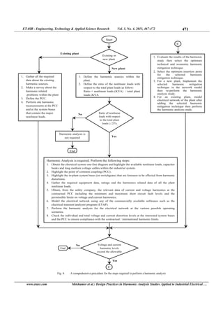
IV. STEPS OF PERFORMING A HARMONIC ANALYSIS STUDY
If a harmonic analysis study is required to be performed
due to any of the cases described in section (II), the following
steps should be followed:
a. Obtain the electrical system one-line diagram and
highlight the available nonlinear loads, capacitor banks
and medium voltage cables of long length within the
industrial system.
b. Highlight the point of common coupling (PCC) which is
the point that connects the industrial network with the
utility or with the neighboring plant.
c. Highlight the in-plant system buses that are expected to be
affected from harmonic distortions.
d. Gather the harmonics-related data of all nonlinear loads
within the plant.
e. Obtain, from the utility company, the relevant data of
current and voltage harmonics at the contractual PCC
including the minimum and maximum short circuit fault
levels and the permissible limits on voltage and current
harmonics because the allowable harmonic limits vary
from country to country.
f. Model the electrical network using any of the
commercially available softwares such as the electrical
transient analyzer program (ETAP).
g. Perform the harmonic analysis for the electrical network
at the various possible operating scenarios.
h. Check the individual and total voltage and current
distortion levels at the interested system buses and at the
PCC.](https://image.slidesharecdn.com/harmonicanalysisprocedure-190603151621/85/Harmonic-analysis-procedure-3-320.jpg)
![ETASR - Engineering, Technology & Applied Science Research Vol. 3, No. 4, 2013, 467-472 470
www.etasr.com Mekhamer et al.: Design Practices in Harmonic Analysis Studies Applied to Industrial Electrical …
i. Check the harmonic frequency spectrum, which is a plot
of each individual harmonic value with respect to the
fundamental value versus frequency.
j. If the harmonic distortion results exceed the allowable
limits, select an appropriate harmonic mitigation solution
and the optimum insertion point for that solution. Further
details about this point are introduced in section (V).
k. Re-perform the harmonic analysis study after adding the
harmonic mitigation technique to ensure compliance with
the contractual / international harmonic limits.
An extensive literature review over the past twenty years
leads to the fact that there is no single article that summarizes
the steps required to perform a harmonic analysis study even
though the importance of this procedure for the design
engineers. The comprehensive flowchart presented in Figure 4
provides this novel helpful approach.
V. SELECTION OF THE HARMONIC FILTER'S INSERTION POINT
Even if the design engineer selects the optimum harmonic
mitigation technique for his plant, among the available
harmonic mitigation solutions in the market [5], then the filter
insertion point should be studied carefully as it greatly affects
system performance [6]. As shown in Figure 5, the possible
filter insertion points can be classified into three categories as
follow:
A. Local Harmonic Mitigation
In this mode of mitigation, the shunt type (passive or
active) harmonic filter is directly connected to the nonlinear
load terminals. This mode is efficient if the number of
nonlinear loads is limited and the power of each nonlinear load
is significant compared to the total plant power. Circulation of
harmonic currents in the electrical network is avoided, thus the
harmonic impact on the upstream network elements is
minimized.
B. Semi-Global Harmonic Mitigation
In this mode of mitigation, the shunt type (passive or
active) harmonic filter is connected to the input of the LV sub-
distribution switchboard. Accordingly, the filter treats several
sets of nonlinear loads. This type of compensation is ideal in
presence of multiple nonlinear loads each having low rated
power. A practical example of this mode is found in
commercial buildings where a harmonic filter may be found on
each floor of the building.
C. Global Harmonic Mitigation
This mode of mitigation is more concerned with meeting
the contractual harmonic limits at the (PCC) than the reduction
of the in-plant harmonics. The major drawback of this
mitigation mode is that the harmonic currents are allowed to
circulate in the electrical network. Thus, the various electrical
elements within the plant will be subjected to harmful
harmonic impact.
VI. INTERNATIONAL HARMONIC STANDARDS
The purpose of imposing strict limits on the harmonics
emissions is to ensure that the current and voltage distortions at
the PCC are kept sufficiently low. Thus, the other customers
connected at the same point are not disturbed. The international
standards related to harmonic distortion limits can be classified
as follows:
A. Standards specifying limits for individual nonlinear
equipment
IEC 61000-3-2 [7], which specifies the current harmonic
limits for low voltage equipment that has an input current
less than 16 A.
IEC 61000-3-12 [8], which specifies the current harmonic
limits for an equipment that has an input current between
16A and 75A
IEC 61800-3 [9],which specifies the electro-magnetic
compatibility (EMC) requirements of the adjustable speed
drive systems
As noticed, the above standards are for small rating and low
voltage harmonic loads only. In addition, the above standards
do not set limits on the overall distribution network.
B. Standards specifying limits for electrical networks
IEEE 519-1992 [10], this document introduces many
useful recommended practices for harmonics control in
electrical networks. This document is widely used in the
industrial sector and many consultants/clients use the
limits indicated in it as contractual limits within their
specifications.
IEC 61000-3-6 [11], this specification performs an
assessment of the harmonic emission limits for distorting
loads in medium voltage and high voltage power systems.
Up till now, this specification is not widely used in the
industrial sector because it is rather new (punlished in
2008).
British engineering recommendation G5/4-1 [12], this
document provides some helpful engineering
recommendations for establishing the allowable harmonic
limits of the voltage distortions in the United Kingdom.
VII. IEEE 519-1992 HARMONIC LIMITS
A. Harmonic current distortion limits
Harmonic current distortion limits are introduced in the
IEEE 519-1992. A summary of these current harmonic limits is
shown in Table I. Setting limits for the current harmonic levels
protects the utility company and the other utility consumers
connected on the same feeder.
where:
ISC : maximum short circuit current at PCC
I1 or IL: maximum demand load current (fundamental
frequency component) at PCC](https://image.slidesharecdn.com/harmonicanalysisprocedure-190603151621/85/Harmonic-analysis-procedure-4-320.jpg)
![ETASR - Engineering, Technology & Applied Science Research Vol. 3, No. 4, 2013, 467-472 472
www.etasr.com Mekhamer et al.: Design Practices in Harmonic Analysis Studies Applied to Industrial Electrical …
Fig. 5. Various insertion points for the harmonic filters
It should be noted that all the power generation equipment
are limited to these values of current distortion, regardless of
the actual ISC/I1 ratio. The ratio ISC/IL is the ratio of the short
circuit current available at the (PCC) to the maximum
fundamental load current. It is recommended that the load
current (IL) be calculated over any (15) or (30) min period and
then averaged over the next (12) month period.
TABLE I. HARMONIC CURRENT DISTORTION LIMITS FOR GENERAL
DISTRIBUTION SYSTEMS (SYSTEM VOLTAGES: FROM 120V TO 69 KV)
Odd harmonic order h (%)
Individual current harmonic distortion (%)ISC / I1
h < 11 11 ≤ h < 17 17 ≤ h < 23 23 ≤ h <35 h ≥ 35
Total
harmonic
distortion
THDI %
< 20 * 4 2 1.5 0.6 0.3 5
20-50 7 3.5 2.5 1 0.5 8
50-
100
10 4.5 4 1.5 0.7 12
100-
1000
12 5.5 5 2 1 15
>1000 15 7 6 2.5 1.4 20
B. Harmonic voltage distortion limits:
The IEEE 519-1992 defines the allowable voltage harmonic
limits at the PCC. Table II summarizes the limits for the low
voltage systems and Table III summarizes the limits for the
medium and high voltage systems.
Where:
Special systems: critical applications like hospitals and
airports
Dedicated systems: systems that contain only nonlinear
loads
It is important to highlight that the limits listed in Table III
should be used as system design values for normal operation
conditions (lasting more than one hour). For shorter operation
periods, during start-ups or unusual transient conditions, these
harmonic limits may be allowed to exceed by 50%.
TABLE II. HARMONIC VOLTAGE DISTORTION LIMITS FOR LOW VOLTAGE
DISTRIBUTION SYSTEMS (SYSTEM VOLTAGES: BELOW 1 KV)
Allowable voltage
THD
Special
systems
General
distribution
systems
Dedicated
systems
Voltage THD (%) 3% 5% 10%
TABLE III. HARMONIC VOLTAGE DISTORTION LIMITS FOR MEDIUM AND
HIGH VOLTAGE DISTRIBUTION SYSTEMS
Bus voltage
Individual voltage
harmonic distortion
(%)
Total voltage
harmonic
distortion (%)
69 kV and below 3 % 5 %
From 69 kV to 161 kV 1.5 % 2.5 %
161 kV and above 1 % 1.5 %
VIII. CONCLUSIONS
Harmonic analysis studies are necessary to analyze the
current and voltage harmonic levels within any industrial
electrical system and to check if these levels comply with the
contractual or international standard limits. This paper provides
a comprehensive approach for performing a harmonic study,
presented in the form of a flowchart. In addition, this paper
presents the current and voltage harmonic limits used in
industrial systems.
REFERENCES
[1] M. Z. El-Sadek, Power system harmonics, 2nd edition, Mukhtar Press,
Egypt, 2007
[2] R. G. Ellis, “Harmonic analysis of industrial power systems”, IEEE
Transactions on Industry Applications, Vol. 32, No. 2, pp. 417-421,
1996
[3] IEEE Std 399-1997, Recommended practice for industrial and
commercial power systems analysis, ANSI/IEEE, 1997
[4] J. P. Nelson, “A Better understanding of harmonics distortions in the
petrochemical industry”, IEEE Transactions on Industry Applications,
Vol. 40, No. 1, pp. 220-231, 2004
[5] S. F. Mekhamer, A. Y. Abdelaziz, S. M. Ismael, “Technical comparison
of harmonic mitigation techniques for industrial electrical power
systems”, MEPCON 2012, Fifteenth International Middle East Power
Systems Conference, Paper ID: 214, Alexandria, Egypt, 2012
[6] E. Bettega, J. N. Fiorina, Cahier Technique no. 183: Active harmonic
conditioners and unity power factor rectifiers, Schneider Electric, 1st
edition, 1999
[7] IEC Std 61000-3-2, Electromagnetic compatibility (EMC)-Part 3-2:
Limits for harmonic current emissions (equipment input current ≤16 A
per phase, IEC, 2009
[8] IEC Std 61000-3-12, Electromagnetic compatibility (EMC)-Part 3-12:
Limits for harmonic currents produced by equipment connected to
public low-voltage systems with input current >16 a and ≤ 75 a per
phase, IEC, 2011
[9] IEC Std 61800-3, Adjustable speed electrical power drive systems-Part
3: EMC requirements and specific test methods, IEC, 2004
[10] IEEE Std 519, Recommended practice and requirements for harmonics
control in electrical power systems, ANSI/ IEEE, 1992
[11] IEC Std 61000-3-6, Electromagnetic compatibility (EMC)-Part 3-6:
Assessment of emission limits for the connection of distorting
installations to MV, HV and EHV power systems, IEC, 2008
[12] British Engineering Recommendation, Planning levels for harmonic
voltage distortion and the connection of nonlinear equipment to
transmission systems and distribution networks in the United Kingdom,
G5/4-1, 2001](https://image.slidesharecdn.com/harmonicanalysisprocedure-190603151621/85/Harmonic-analysis-procedure-6-320.jpg)


![protection of transmission lines[distance relay protection scheme]](https://cdn.slidesharecdn.com/ss_thumbnails/os-exe3-23-may2011-sr-i-776s21tr-lineprotection-120425095503-phpapp02-thumbnail.jpg?width=640&height=640&fit=bounds)