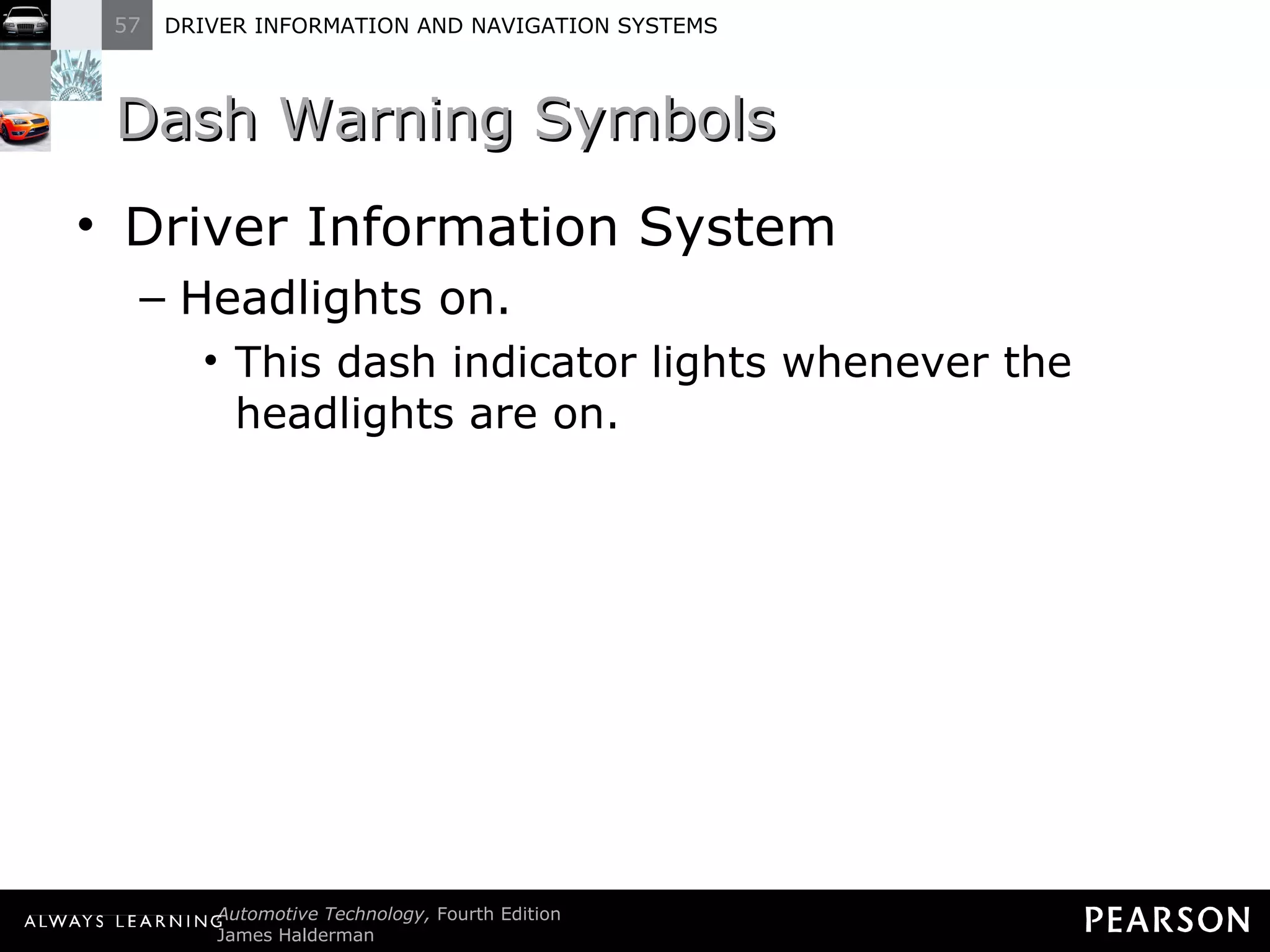
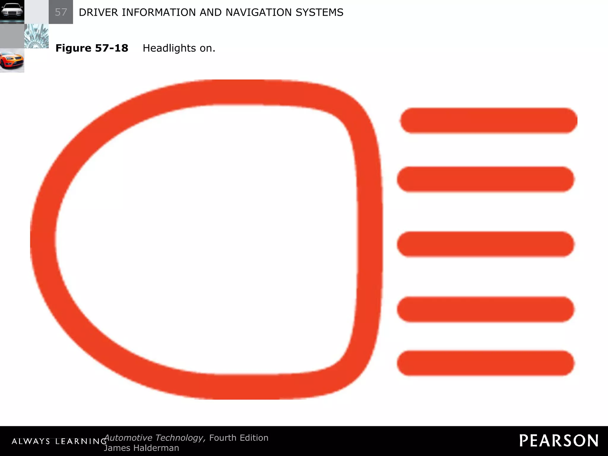
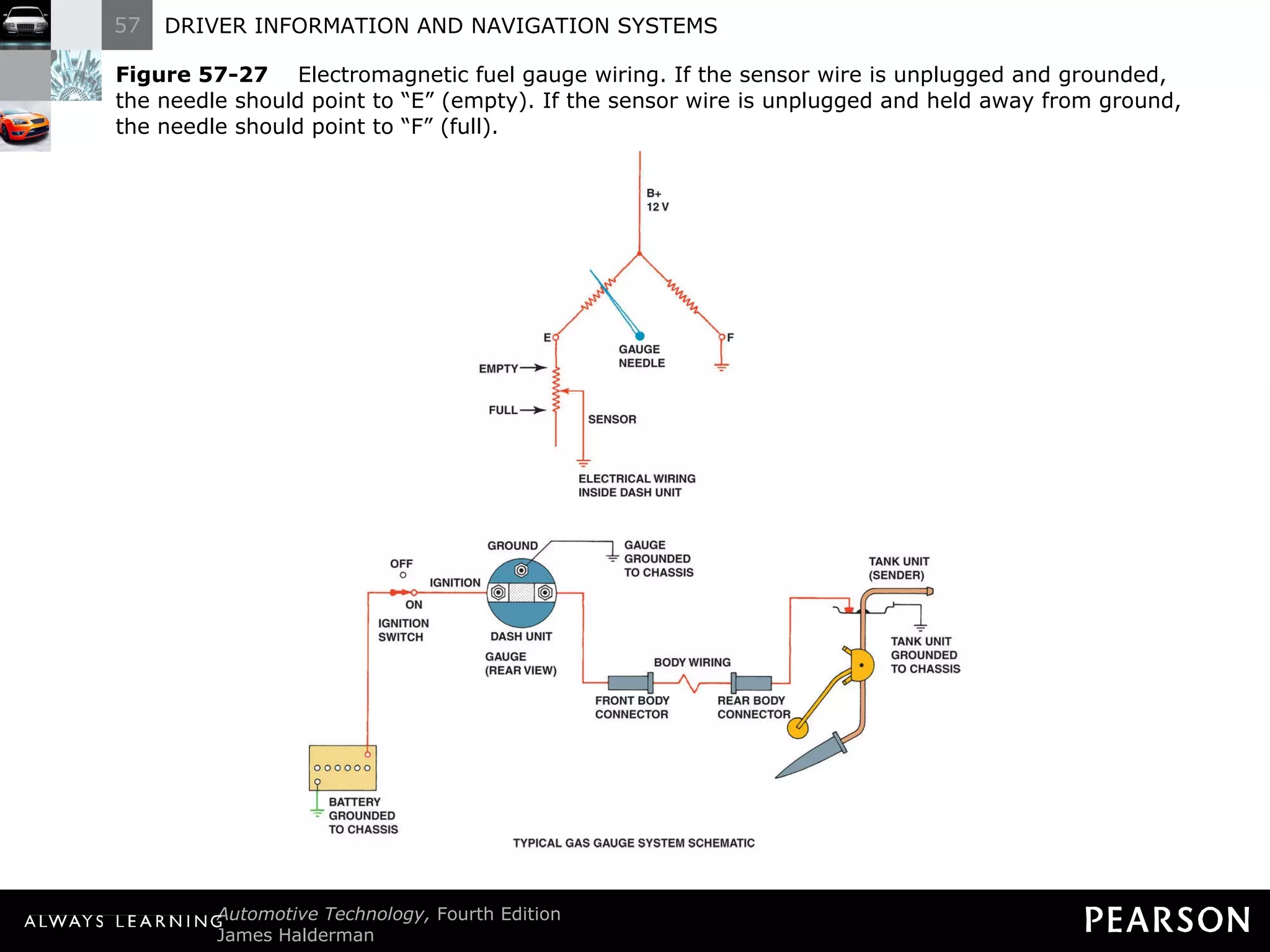
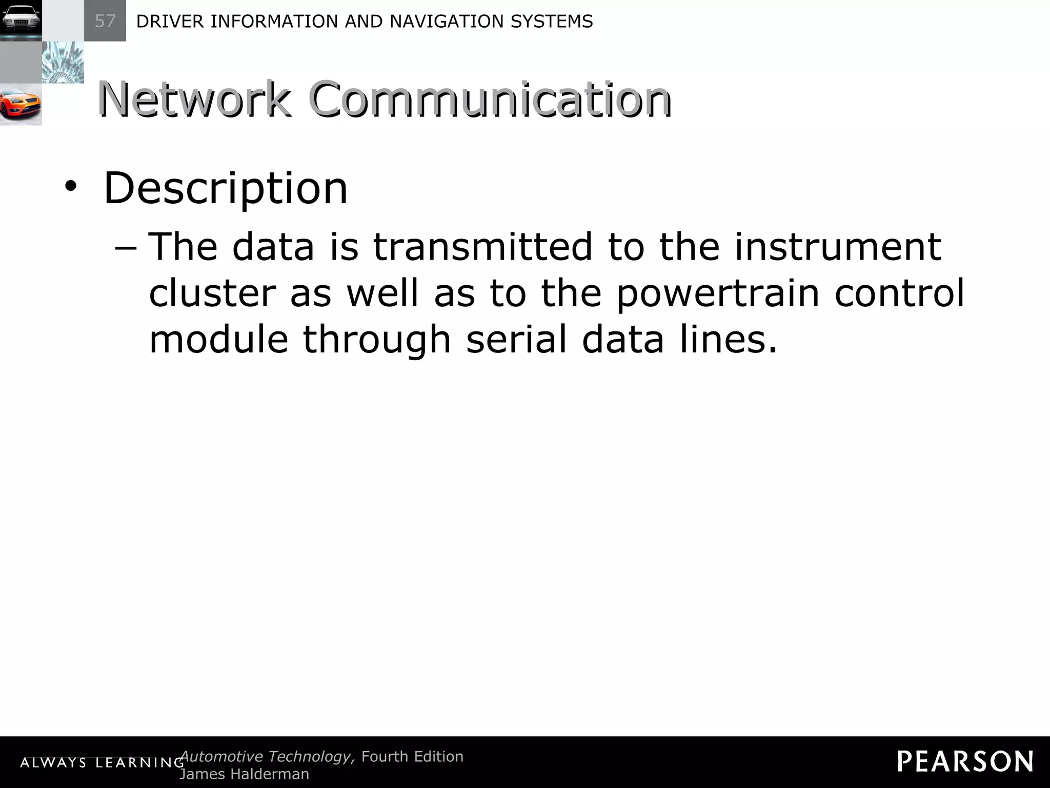
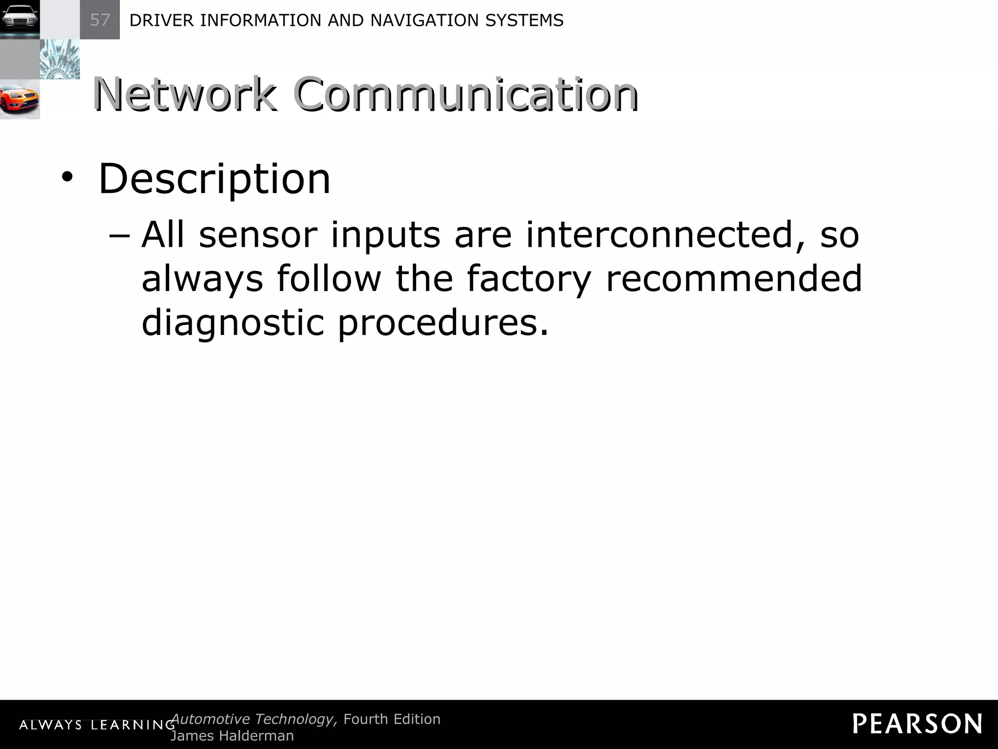
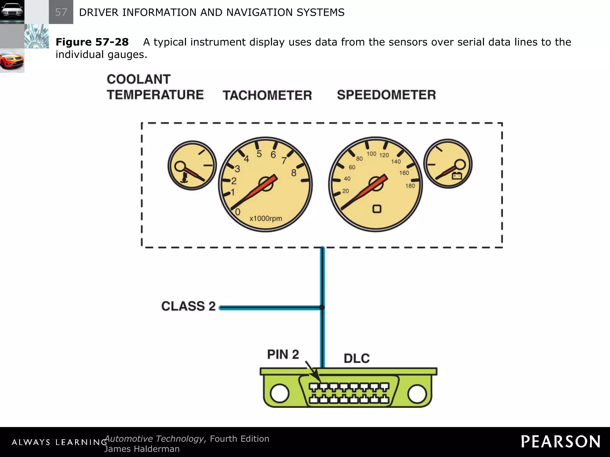
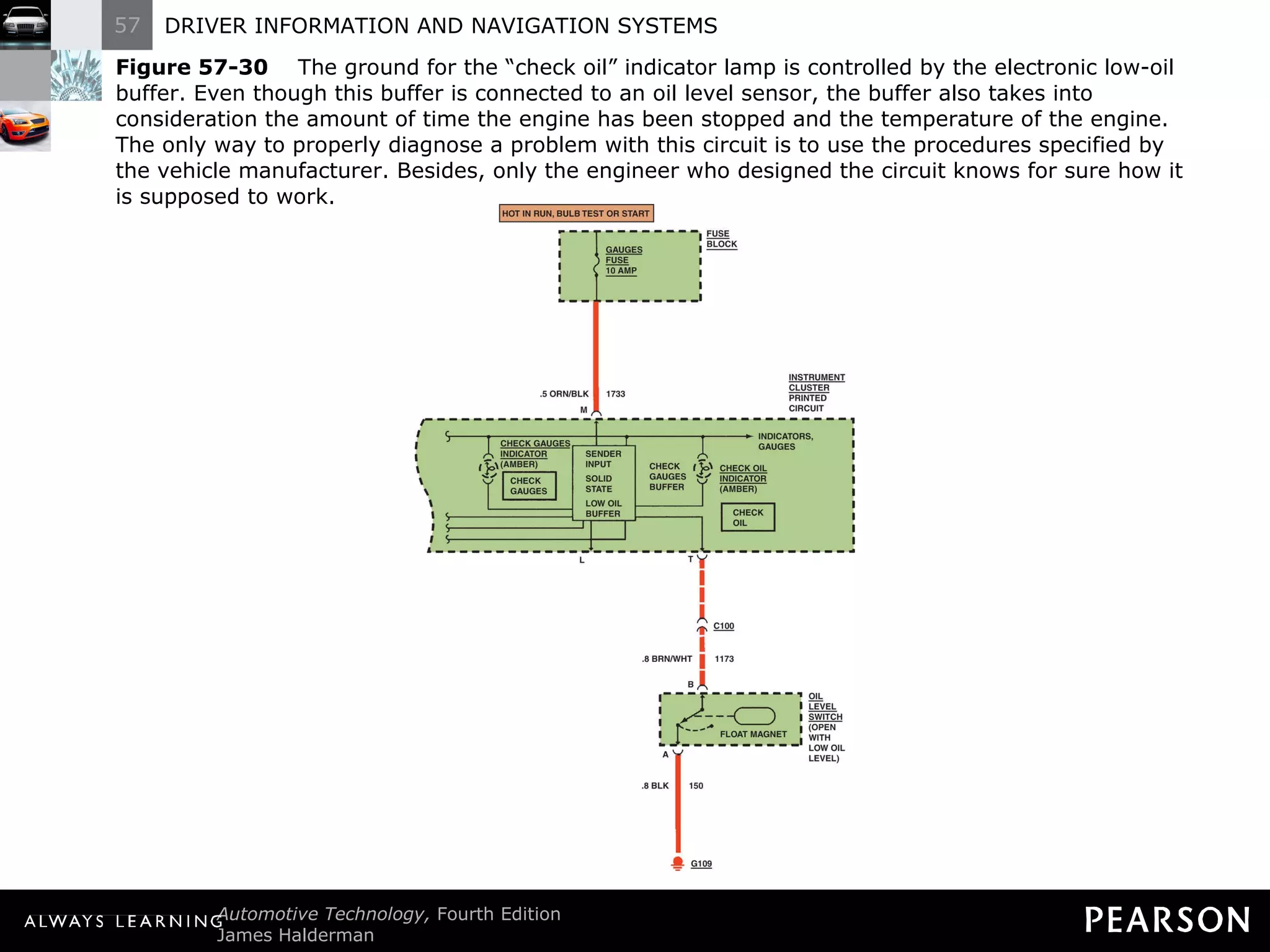
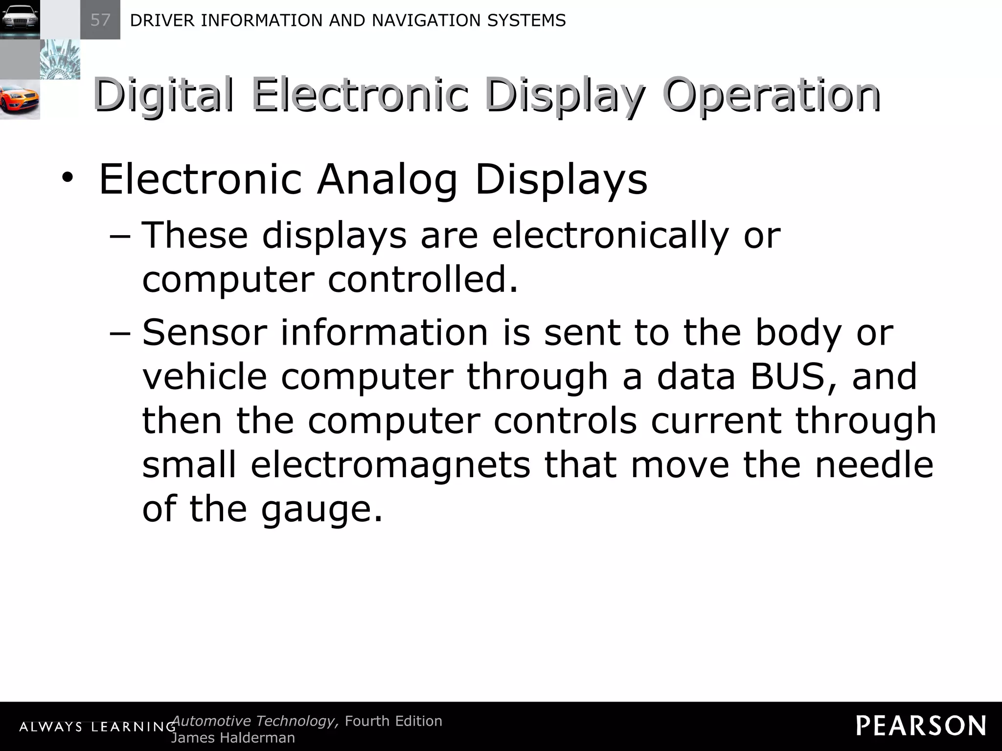
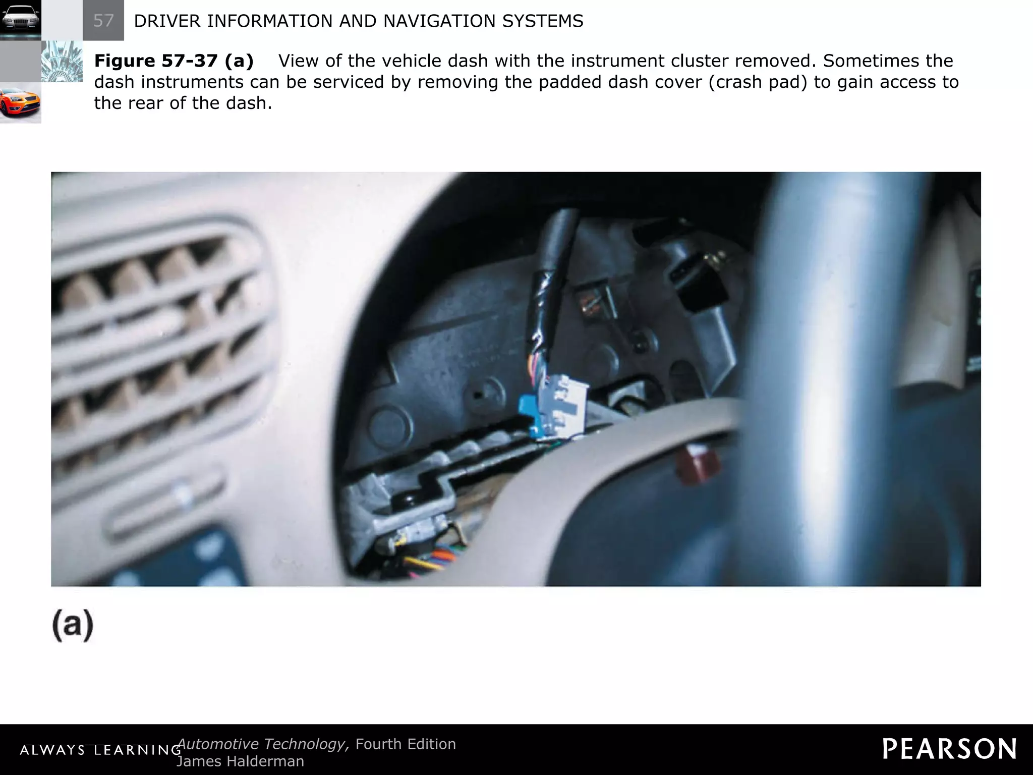
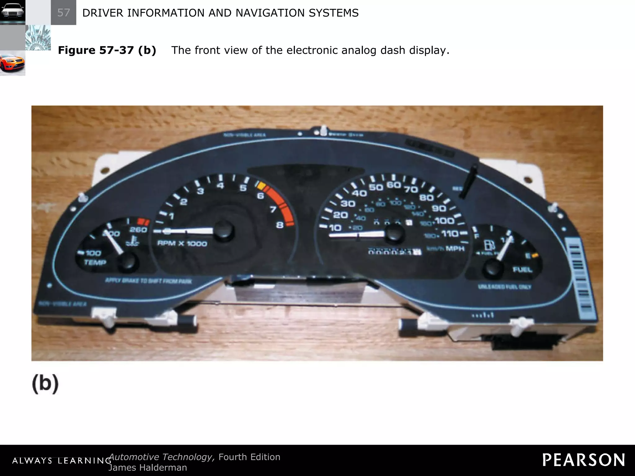
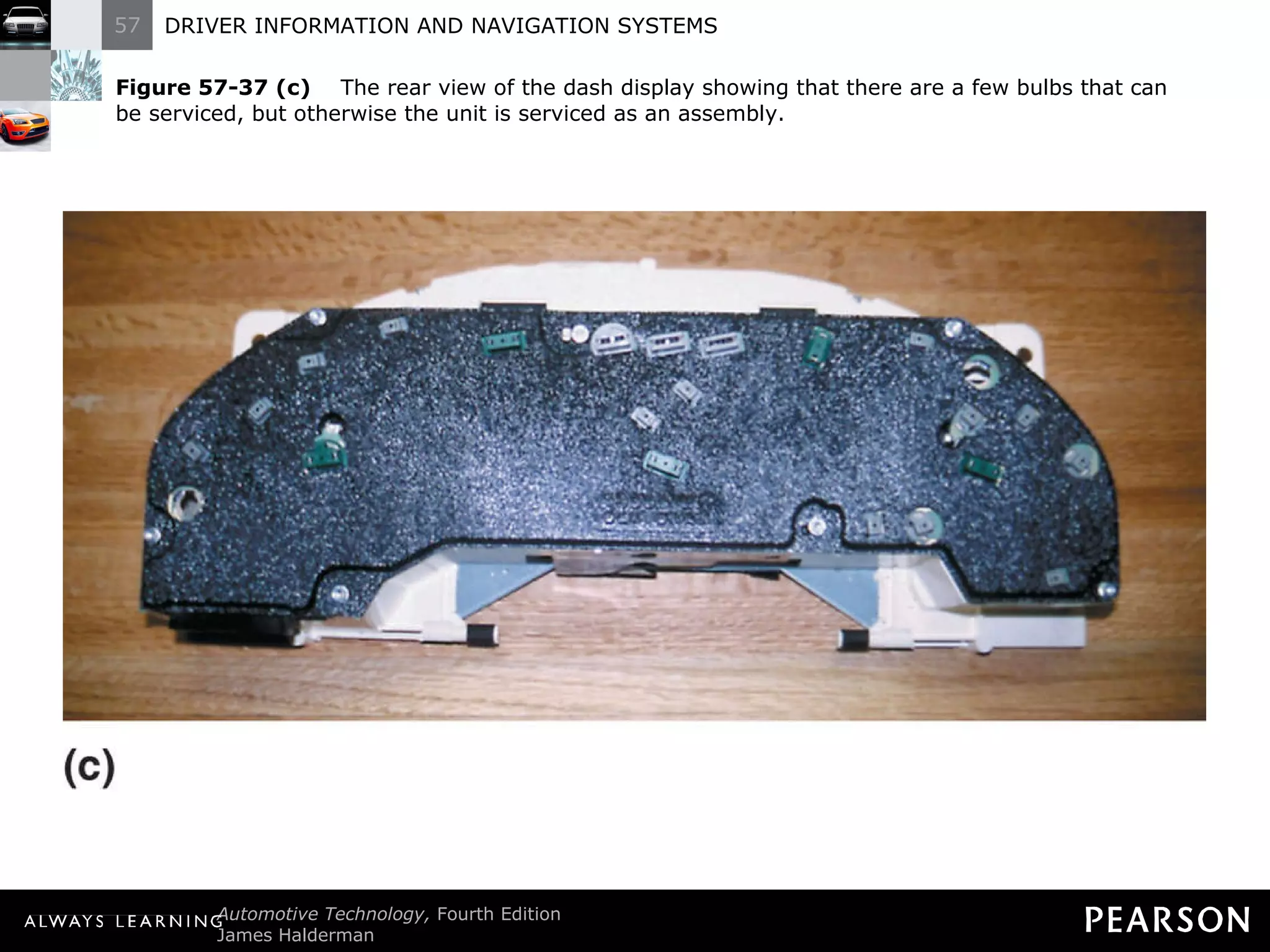
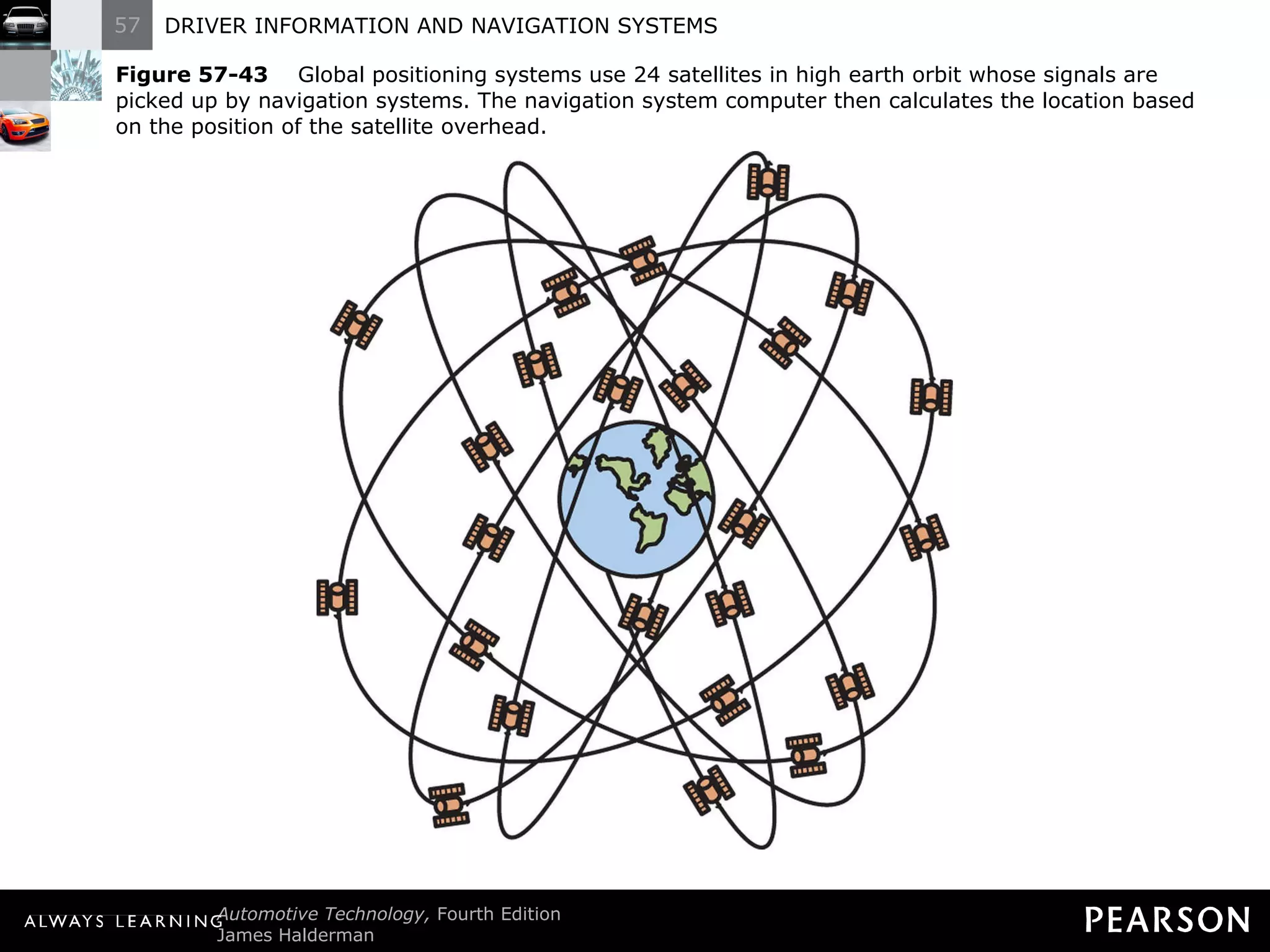
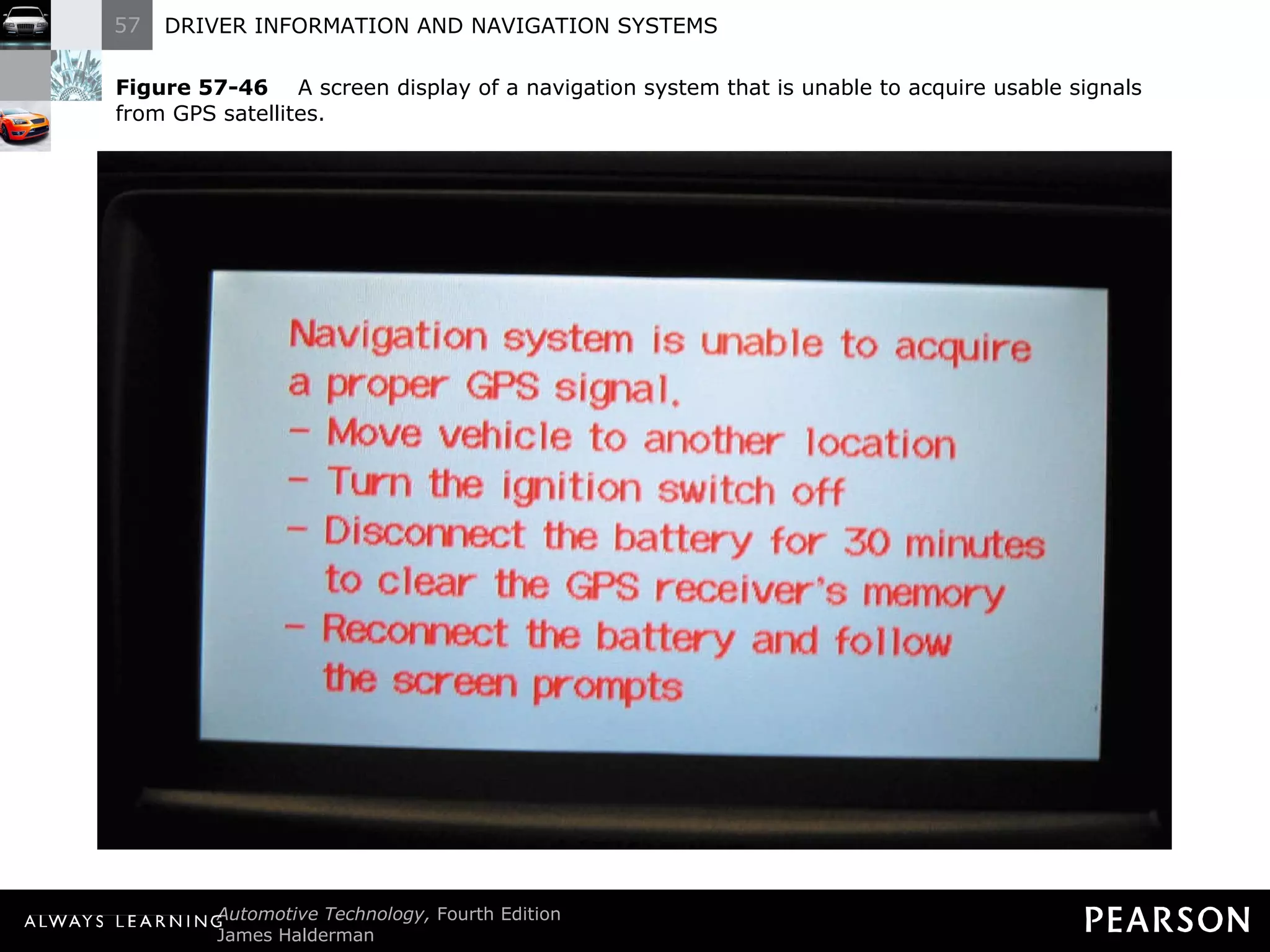
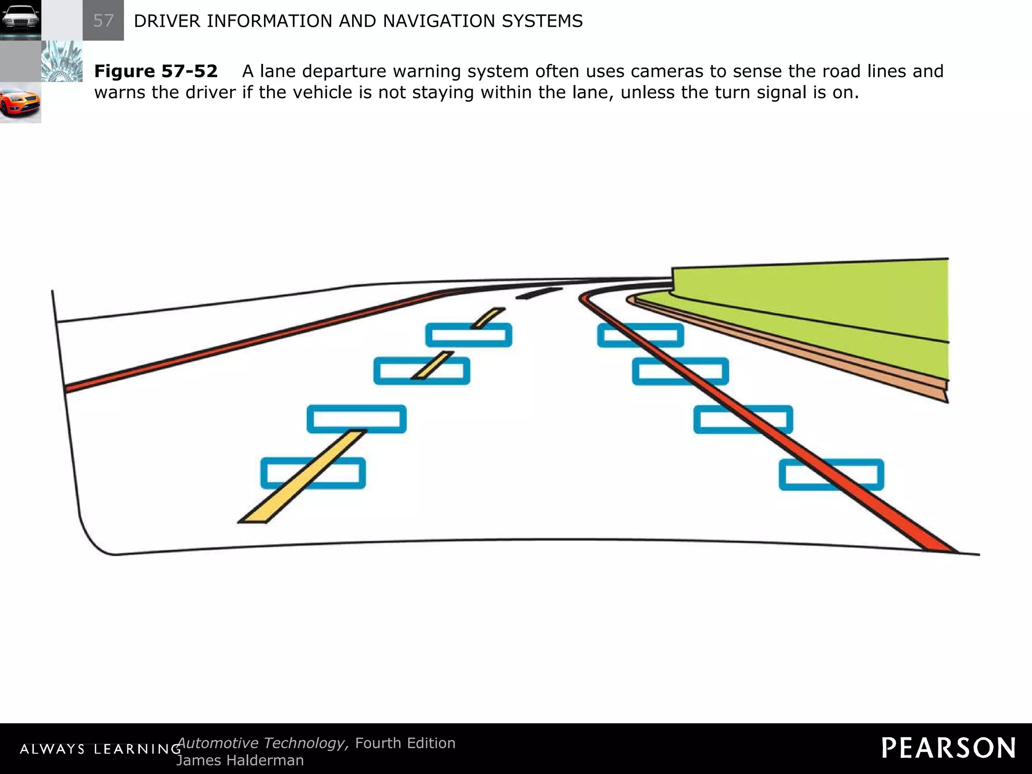
The document discusses driver information and navigation systems, specifically dash warning symbols and their meanings. It describes how various gauges and warning lights function, including oil pressure, temperature, brake, and other systems. It covers analog and digital dash displays, and how they receive sensor data via wiring or network communication to provide vehicle information to the driver.


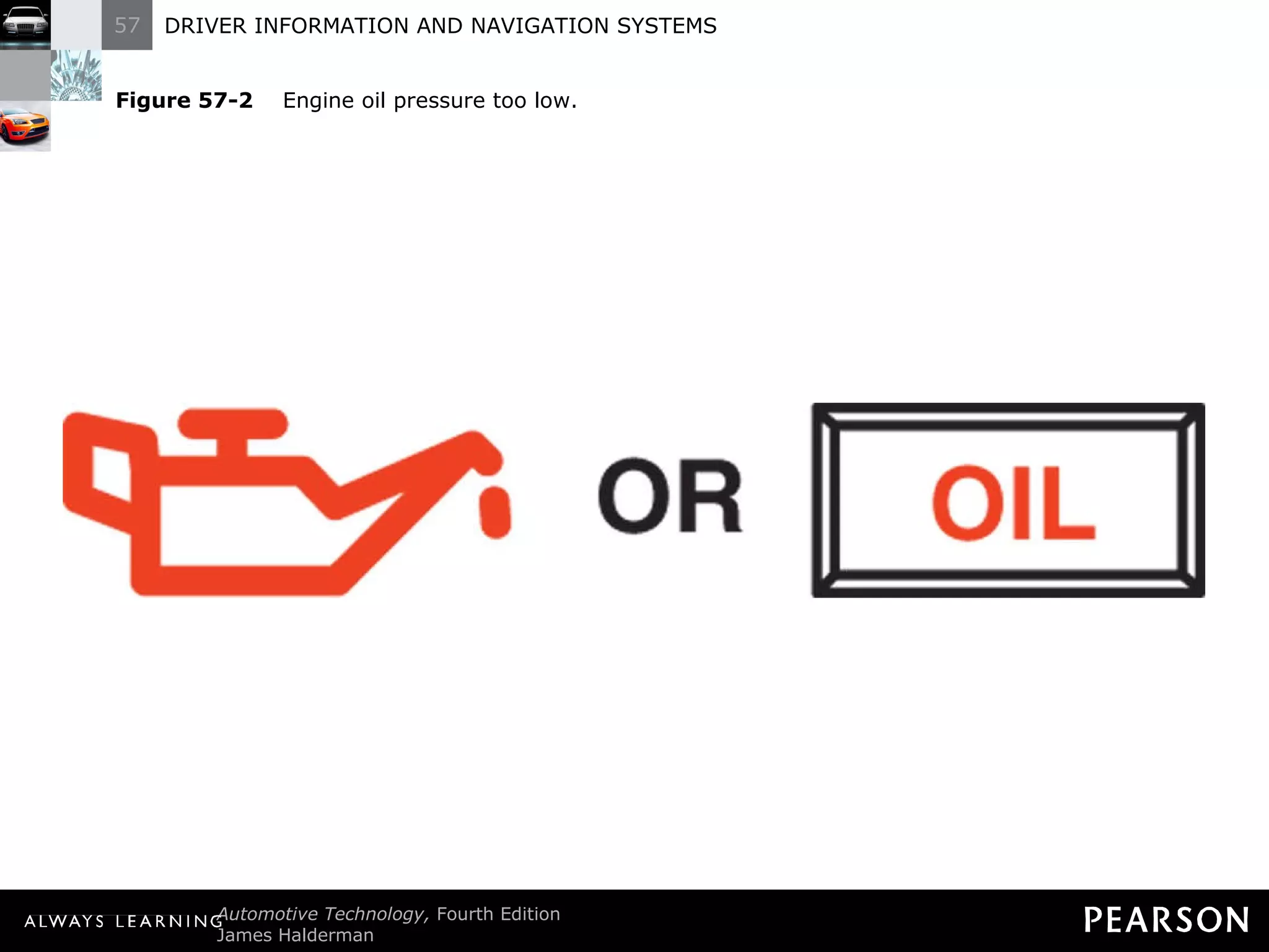


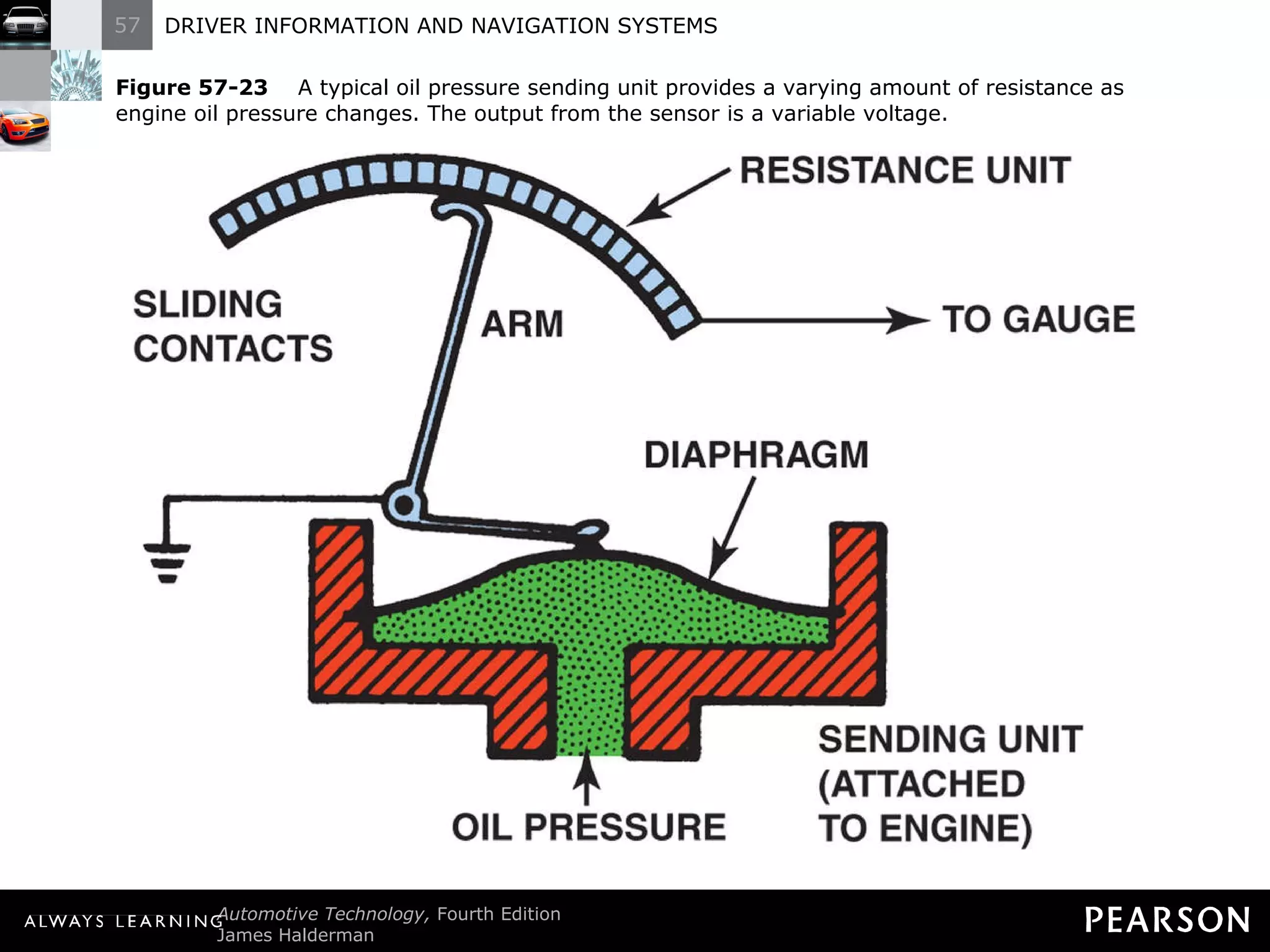
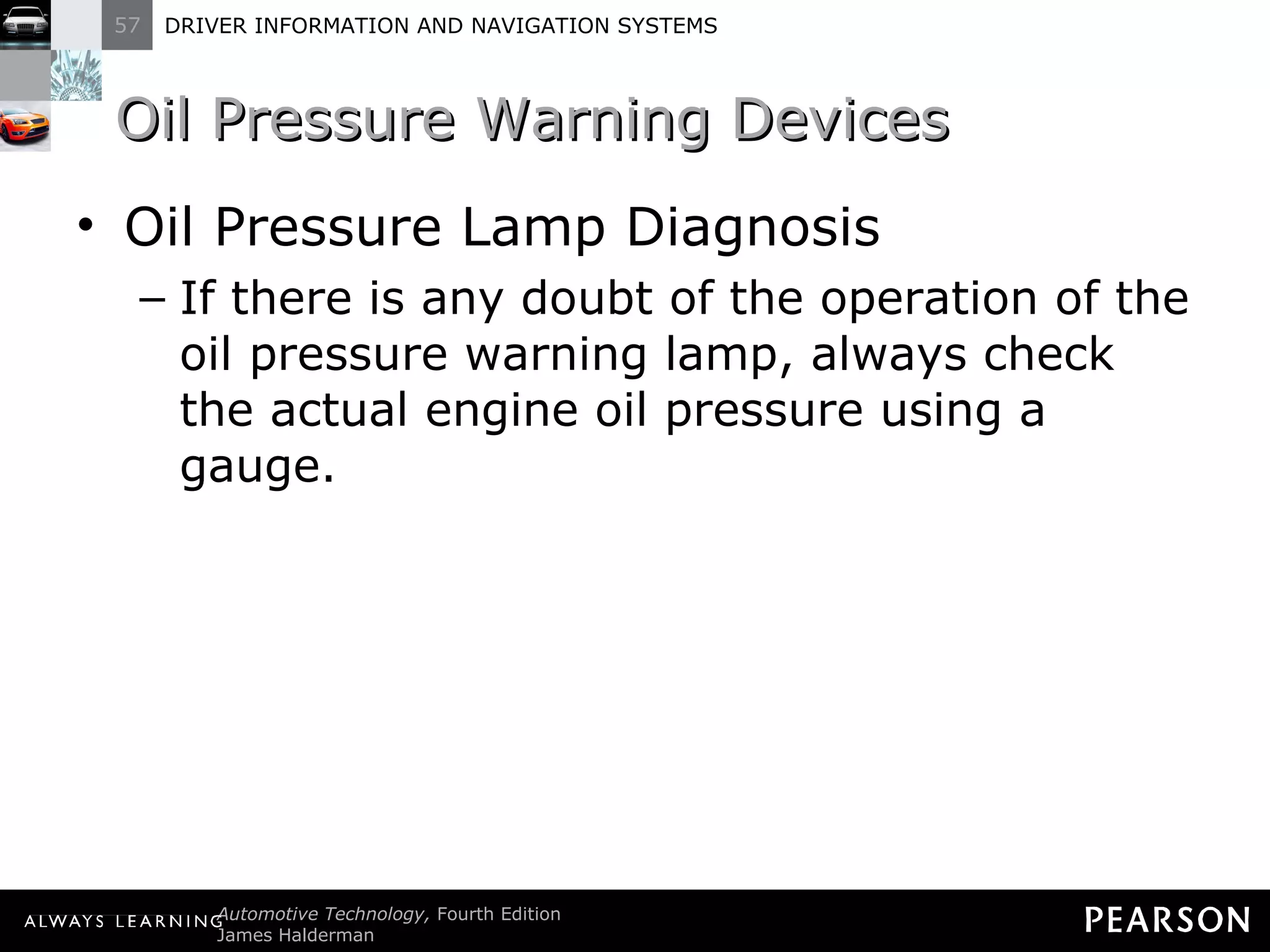
![Oil Pressure Warning Devices Operation The oil pressure lamp operates through use of an oil pressure sensor unit which lights the dash warning lamp when oil pressure is low - 3 to 7 psi (20 to 50 kilopascals [kPa]).](https://image.slidesharecdn.com/haldermanch057lecture-111001170056-phpapp02/75/Halderman-ch057-lecture-82-2048.jpg)


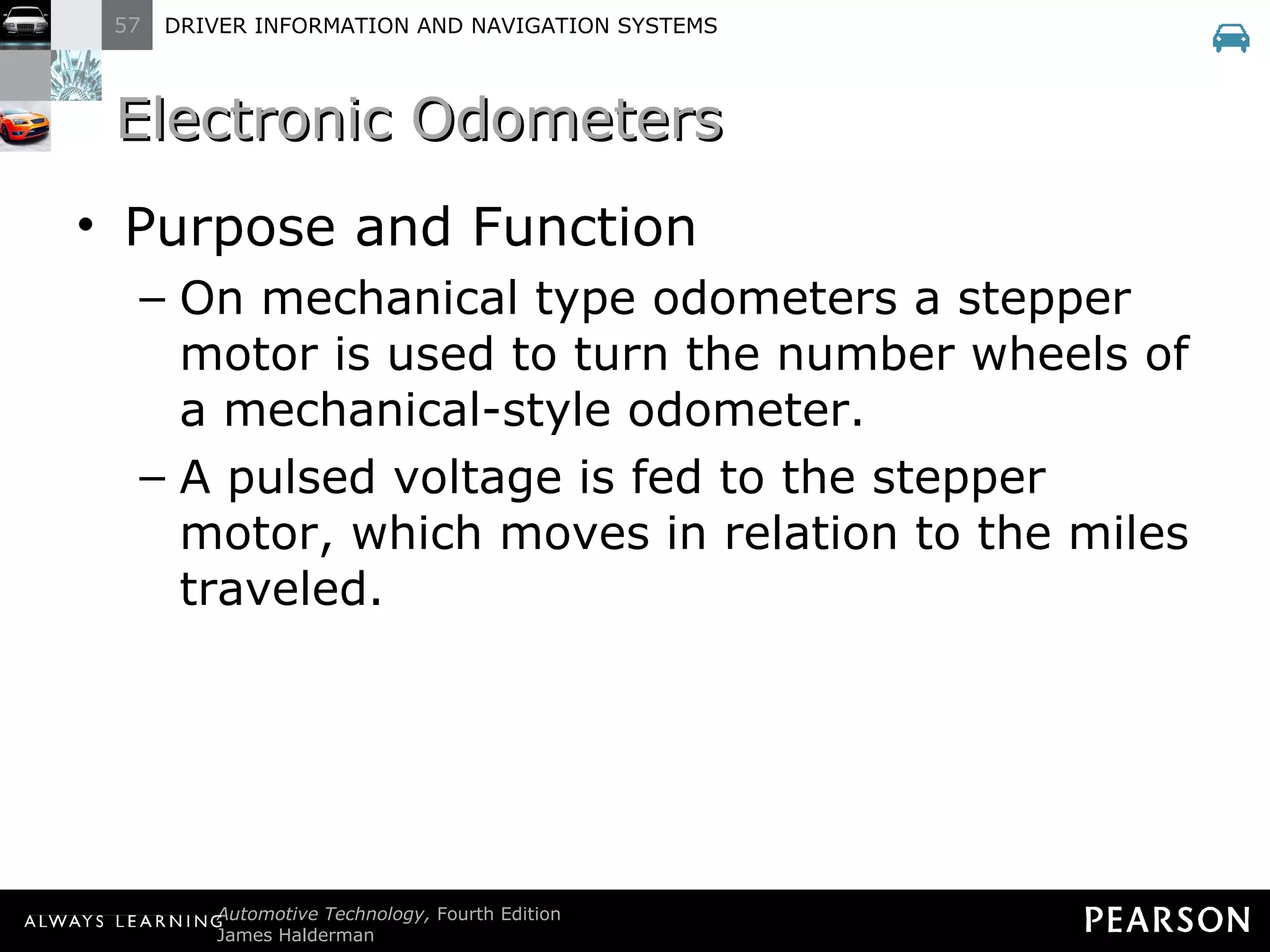
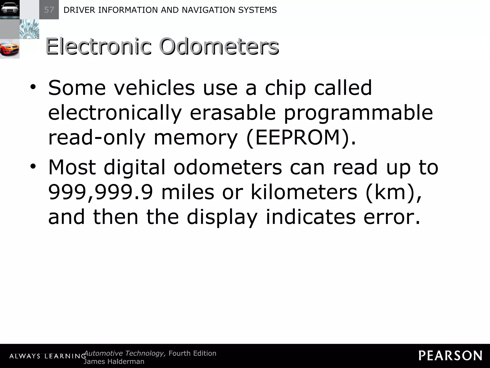
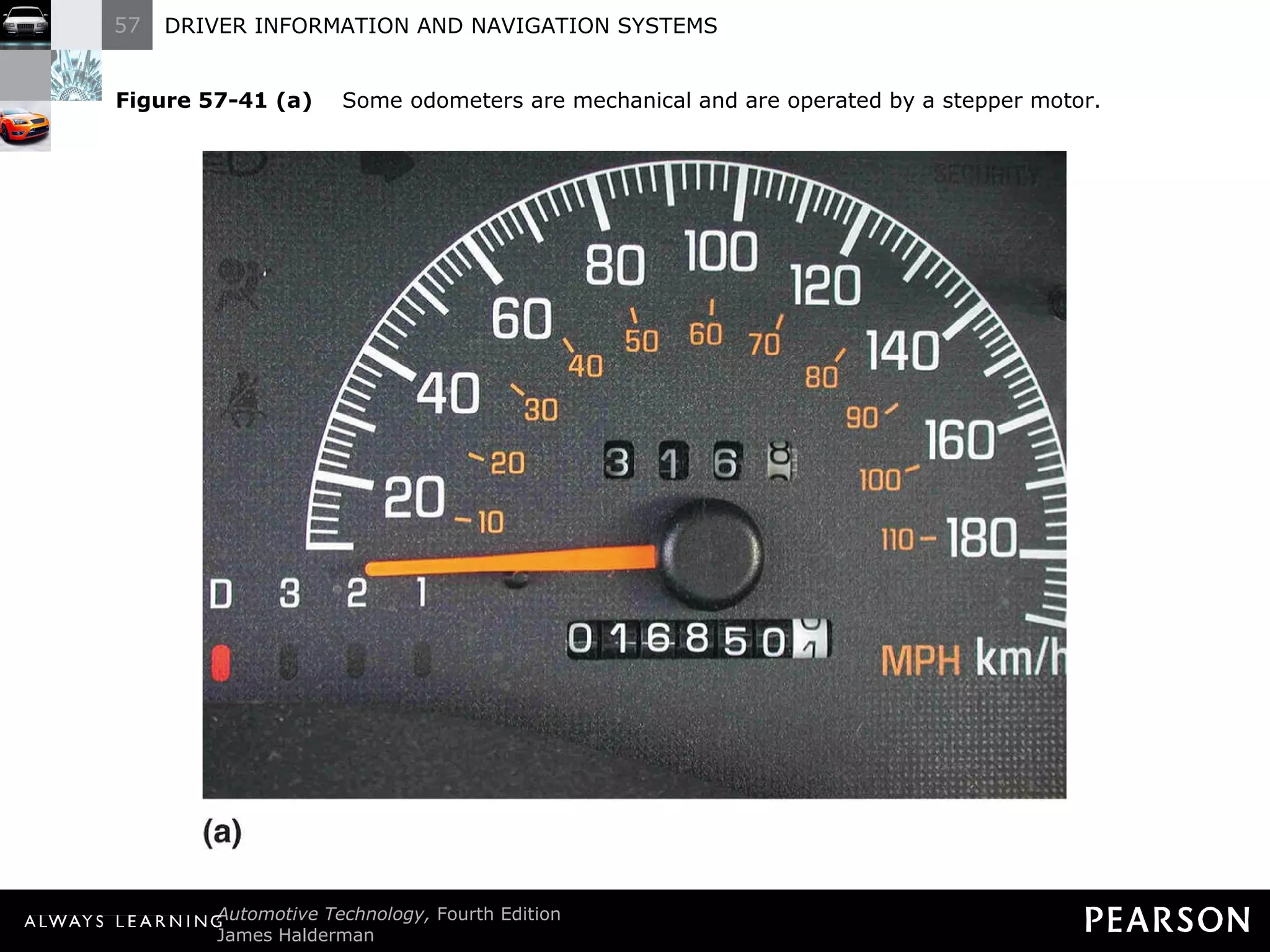
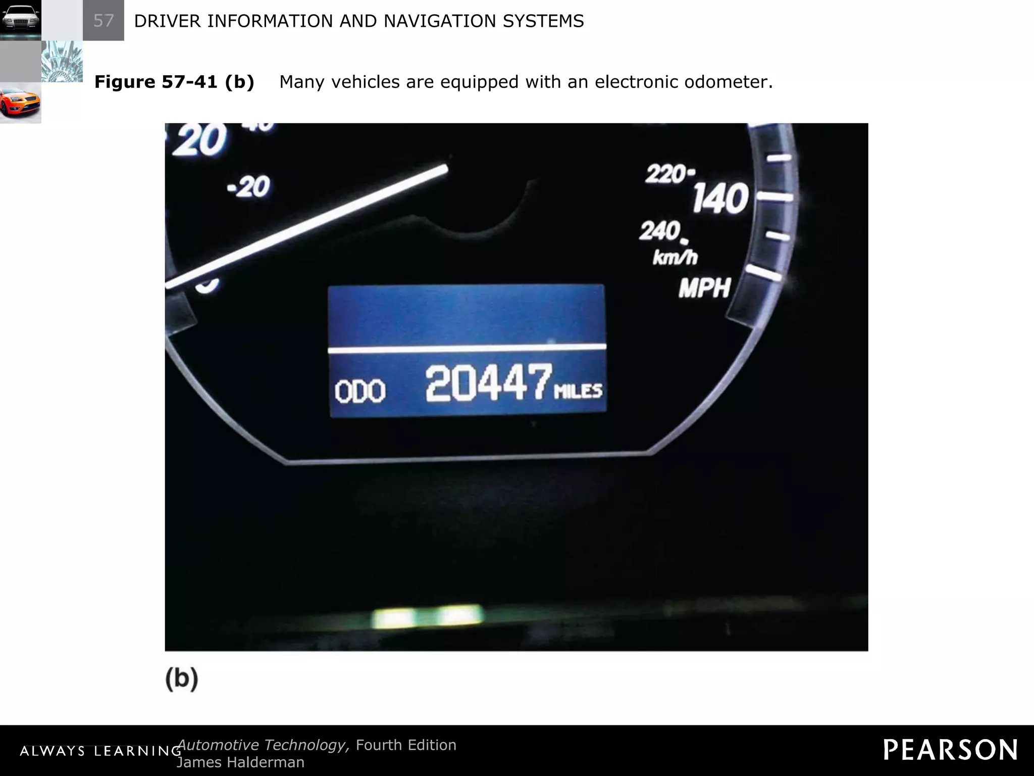
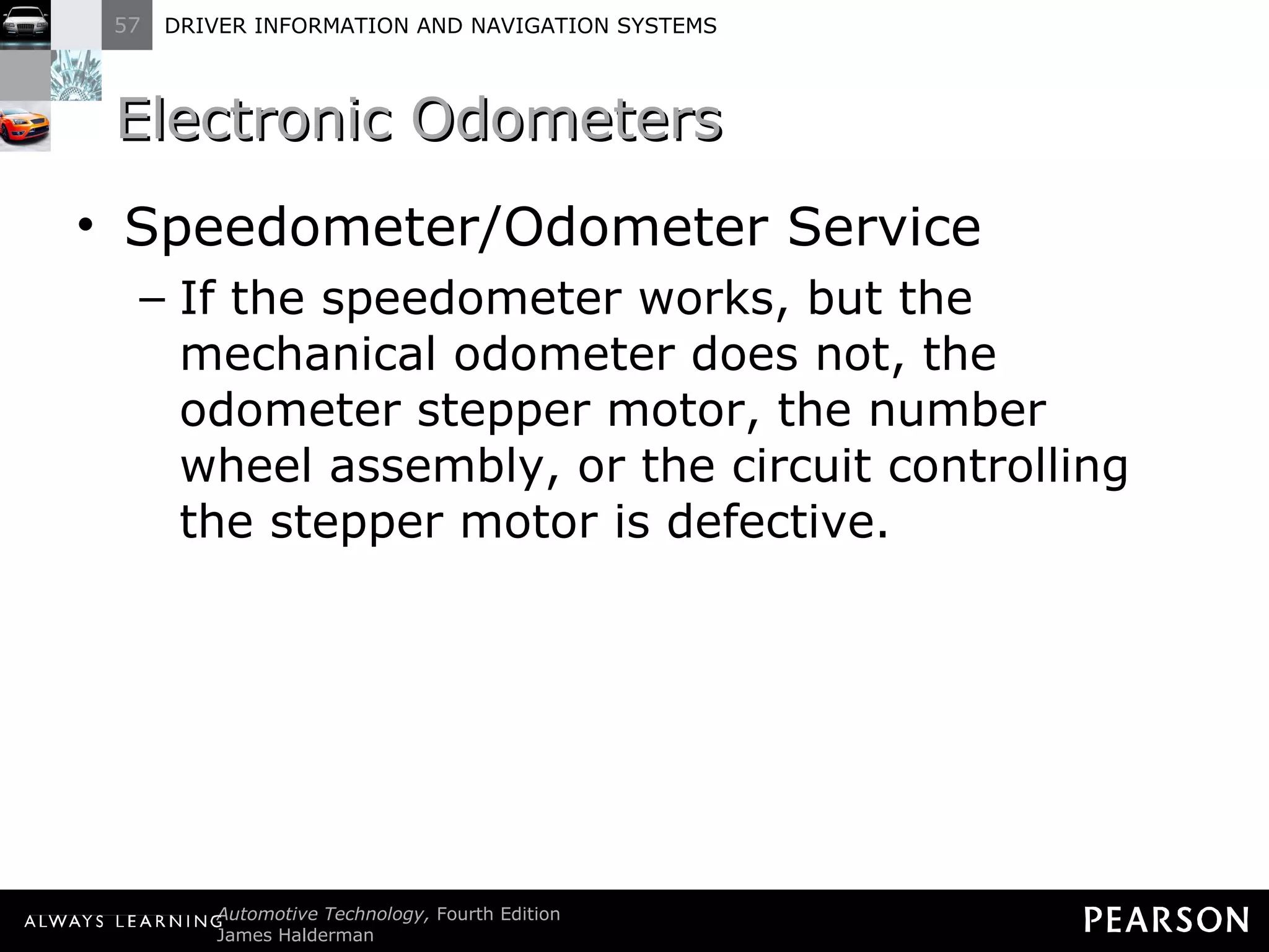
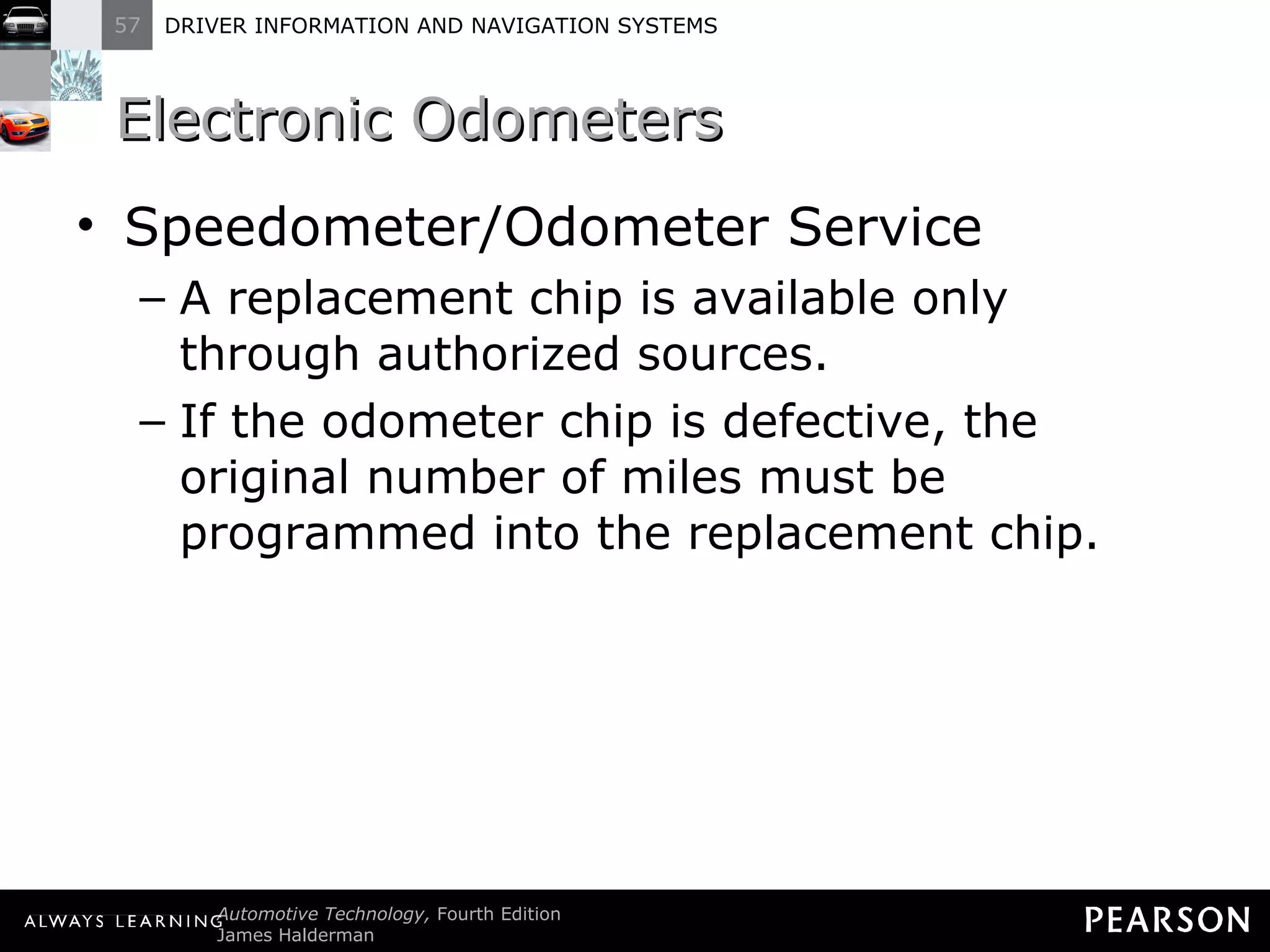
![Electronic Odometers Digital odometers use LED, LCD, or VTF displays. A special electronic chip [nonvolatile random-access memory (NVRAM)] is used to retain the miles traveled when the car is turned off.](https://image.slidesharecdn.com/haldermanch057lecture-111001170056-phpapp02/75/Halderman-ch057-lecture-170-2048.jpg)


![Toyota Dashboard Warning Lights [FULL]](https://cdn.slidesharecdn.com/ss_thumbnails/toyota-warning-lights-211126044903-thumbnail.jpg?width=640&height=640&fit=bounds)