The document provides an overview of vehicle controls and instrumentation for a Ford vehicle. It describes features such as the headlamp control, climate control system, instrument panel gauges, and warning lights. It also provides warnings about proper vehicle operation and maintenance.


![Important supplemental restraint system (SRS)
precautions
The supplemental
restraint system is
designed to work with
the safety belt to help
protect the driver and
right front passenger
from certain upper
body injuries.
Air bags DO NOT
inflate slowly or gently
and the risk of injury
from a deploying air bag is greatest close to the trim
covering the air bag module.
All occupants of the vehicle including the
driver should always properly wear their
safety belts even when air bag SRS is provided.
Always transport children 12 years old and
under in the back seat and always use
appropriate child restraints.
NHTSA recommends a minimum distance of
at least 25.4 cm (ten [10] inches) between
an occupant’s chest and the air bag module.
Seating and safety restraints
67](https://image.slidesharecdn.com/98sable-140905151950-phpapp02/85/98-sable-67-320.jpg)


![ride in your vehicle (generally children who are four
years old or younger and who weigh 18 kg [40 lbs]
or less), you must put them in safety seats made
especially for children. Check your local and state or
provincial laws for specific requirements regarding
the safety of children in your vehicle.
Never let a passenger hold a child on his or
her lap while the vehicle is moving. The
passenger cannot protect the child from injury in a
collision.
Always follow the instructions and warnings that
come with any infant or child restraint you might
use.
When possible, place children in the rear seat of
your vehicle. Accident statistics suggest that
children are safer when properly restrained in the
rear seating positions than in the front seating
position.
Children and safety belts
If the child is the proper size, restrain the child in a
safety seat.
Children who are too large for child safety seats (as
specified by your child safety seat manufacturer)
should always wear safety belts.
Follow all the important safety restraint and air bag
precautions that apply to adult passengers in your
vehicle.
If the shoulder belt portion of a combination lap and
shoulder belt can be positioned so it does not cross
or rest in front of the child’s face or neck, the child
should wear the lap and shoulder belt. Moving the
child closer to the center of the vehicle may help
provide a good shoulder belt fit.
Seating and safety restraints
73](https://image.slidesharecdn.com/98sable-140905151950-phpapp02/85/98-sable-73-320.jpg)


![Severe winter climate
If you drive in extremely cold climates (less than
–36°C [–34°F]), it may be necessary to increase the
coolant concentration above 50%. Refer to the chart
on the coolant container to ensure the coolant
concentration in your vehicle is such that the
coolant will not freeze at the temperature level in
which you drive during winter months. Never
increase the engine coolant concentration above
60%. Leave a 50/50 mixture of engine coolant and
water in your vehicle year-round in non-extreme
climates.
CHECKING AND ADDING POWER STEERING
FLUID
Check the power
steering fluid. Refer to
the “Service Guide” for
the service interval
schedules. If adding
fluid is necessary, use
only MERCON ATF.
1. Start the engine and let it run until it reaches
normal operating temperature (the engine coolant
temperature gauge indicator will be near the center
of the normal area between H and C).
2. While the engine idles, turn the steering wheel
left and right several times.
3. Turn the engine off.
Perform steps 4 and 5 following the procedure for
your engine.
Maintenance and care
138](https://image.slidesharecdn.com/98sable-140905151950-phpapp02/85/98-sable-138-320.jpg)

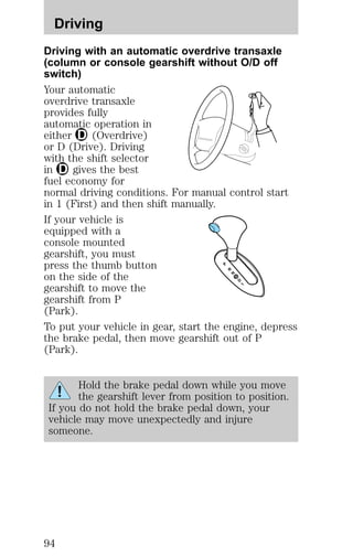
![TRANSMISSION FLUID
Checking automatic transmission fluid
Refer to your “Service Guide” for scheduled intervals
for fluid checks and changes. Your transaxle does
not consume fluid. However, the fluid level should
be checked if the transaxle is not working properly,
i.e., if the transaxle slips or shifts slowly or if you
notice some sign of fluid leakage.
Automatic transmission fluid expands when
warmed. To obtain an accurate fluid check,
drive the vehicle until it is warmed up
(approximately 30 km [20 miles]). If your
vehicle has been operated for an extended
period at high speeds, in city traffic during hot
weather or pulling a trailer, the vehicle should
be turned off for about 30 minutes to allow
fluid to cool before checking.
1. Drive the vehicle 30 km (20 miles) or until it
reaches normal operating temperature.
2. Park the vehicle on a level surface and engage the
parking brake.
3. With the parking brake engaged and your foot on
the brake pedal, start the engine and move the
gearshift lever through all of the gear ranges. Allow
sufficient time for each gear to engage.
4. Latch the gearshift lever in P (Park) and leave the
engine running.
5. Remove the dipstick, wiping it clean with a clean,
dry lint free rag.
6. Install the dipstick making sure it is fully seated in
the filler tube.
7. Remove the dipstick and inspect the fluid level.
The fluid should be in the designated areas for
normal and room temperature.
Maintenance and care
140](https://image.slidesharecdn.com/98sable-140905151950-phpapp02/85/98-sable-140-320.jpg)
![Low fluid level
Do not drive the
vehicle if the fluid level
is at the bottom of the
dipstick and the outside temperatures are above
10°C (50°F).
Correct fluid level
The transmission fluid should be checked at normal
operating temperatures 66°C-77°C (150°F-170°F) on
a level surface. The normal operating temperature
can be reached after approximately 30 km (20
miles) of driving.
The transmission fluid
should be in this range
if at normal operating
temperature (66°C-77°C [150°F-170°F]).
High fluid level
Fluid levels above the
safe range may result
in transaxle failure. An
overfill condition of transmission fluid may cause
shift and/or engagement concerns and/or possible
damage.
High fluid levels can be caused by an overheating
condition.
Adjusting automatic transmission fluid levels
Before adding any fluid, make sure the correct type
is used. The type of fluid used is normally indicated
on the dipstick and/or dipstick handle and also in
the Lubricant specifications section in the
Capacities and specifications chapter.
Use of a non-approved automatic transmission
fluid may cause internal transmission
component damage.
If necessary, add fluid in 250 mL (1/2 pint)
increments through the filler tube until the level is
correct.
DON’T ADD IF IN CROSSHATCH AREA--CHECH WHEN HOT-IDLING
DON’T ADD IF IN CROSSHATCH AREA--CHECH WHEN HOT-IDLING
DON’T ADD IF IN CROSSHATCH AREA--CHECH WHEN HOT-IDLING
Maintenance and care
141](https://image.slidesharecdn.com/98sable-140905151950-phpapp02/85/98-sable-141-320.jpg)