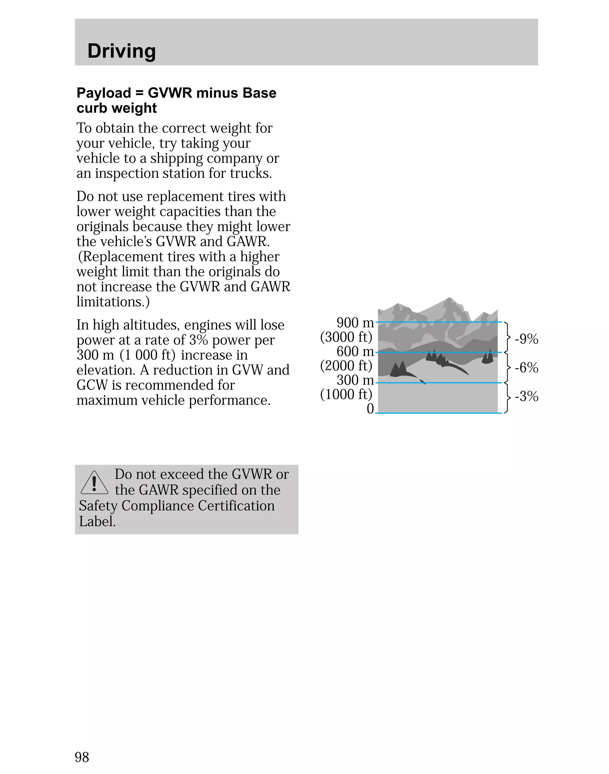
This document provides an overview of instrumentation and controls for a vehicle. It describes the function of various dashboard controls and indicators, including those for headlights, turn signals, windshield wipers, climate control, audio system, and more. Safety features such as airbags and seatbelts are also briefly covered. The document also includes information on starting and driving the vehicle, as well as basic maintenance.


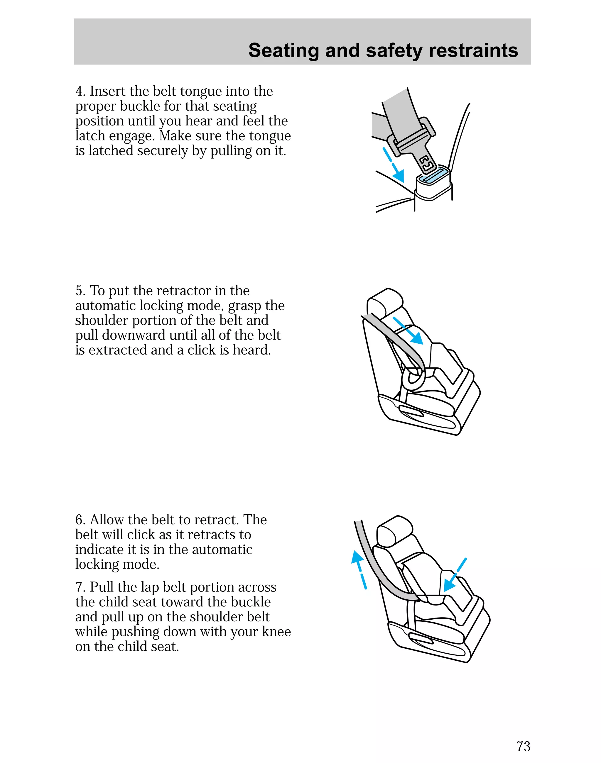
![Seating and safety restraints
Important child restraint
precautions
You are required by law to use
safety restraints for children in the
U.S. and Canada. If small children
ride in your vehicle (generally
children who are four years old or
younger and who weigh 18 kg
[40 lbs] or less), you must put them
in safety seats made especially for
children. Check your local and
state or provincial laws for specific
requirements regarding the safety
of children in your vehicle.
62
Never let a passenger hold a
child on his or her lap while
the vehicle is moving. The
passenger cannot protect the child
from injury in a collision.
Always follow the instructions and
warnings that come with any infant
or child restraint you might use.
When possible, place children in
the rear seat of your vehicle.
Accident statistics suggest that
children are safer when properly
restrained in the rear seating
positions than in the front seating
position.](https://image.slidesharecdn.com/98mystique-140905151947-phpapp01/75/98-mystique-62-2048.jpg)


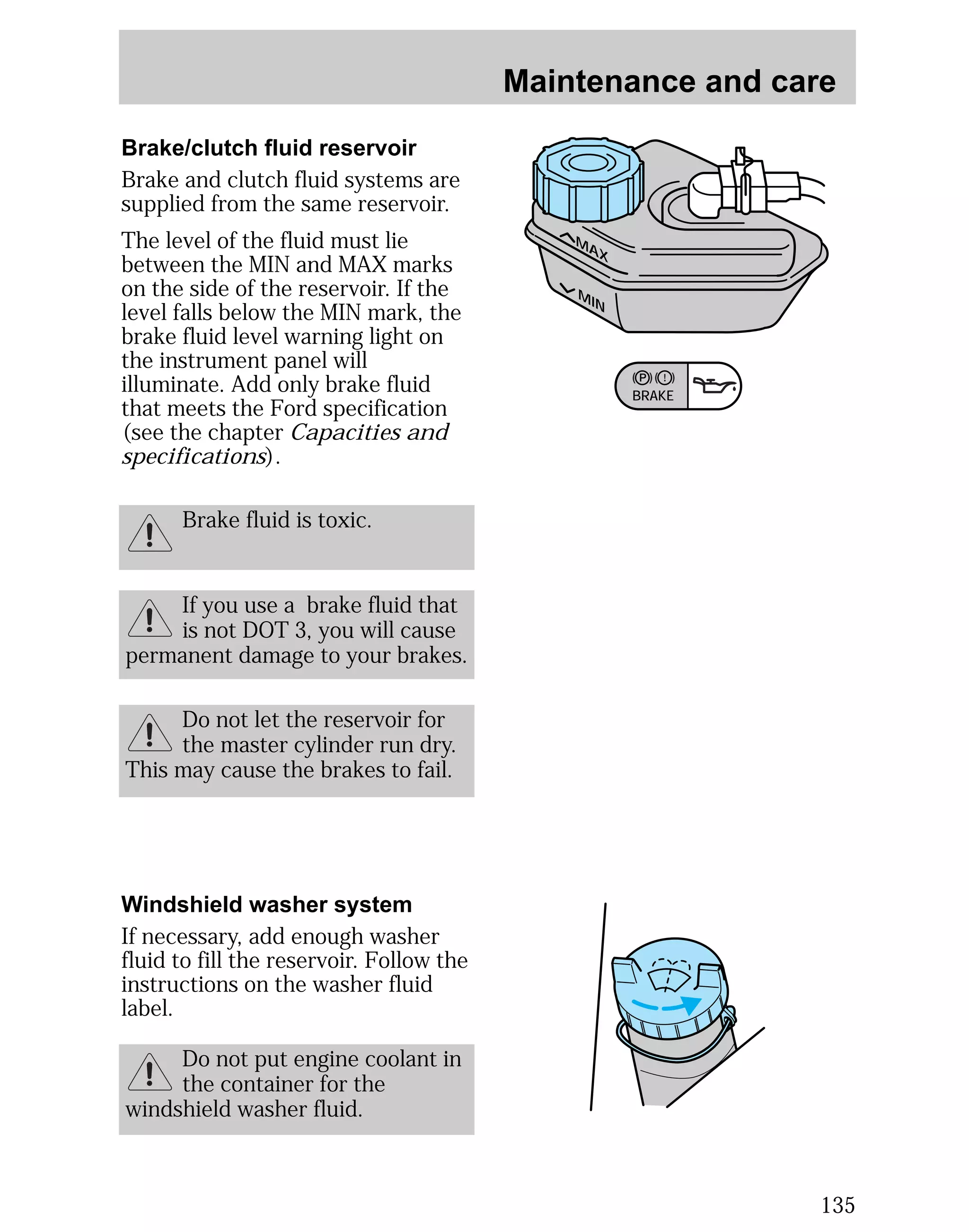
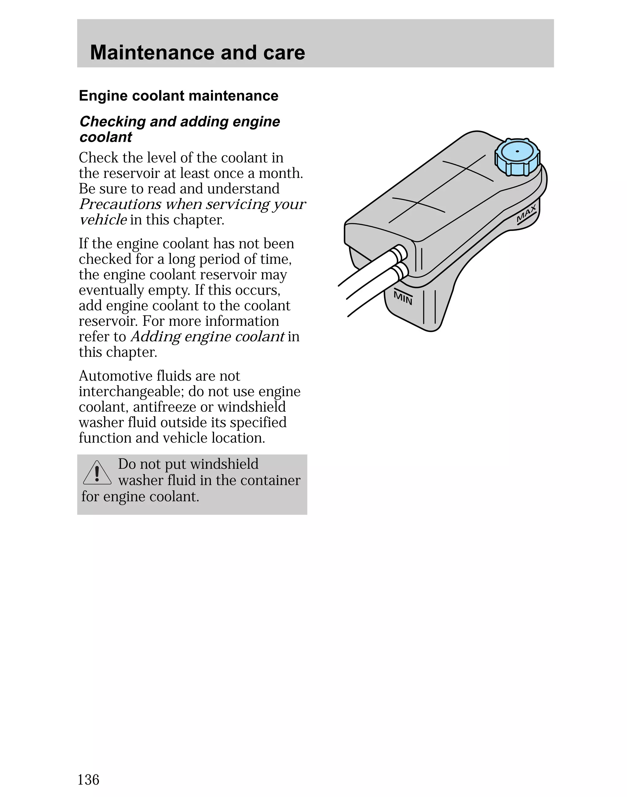
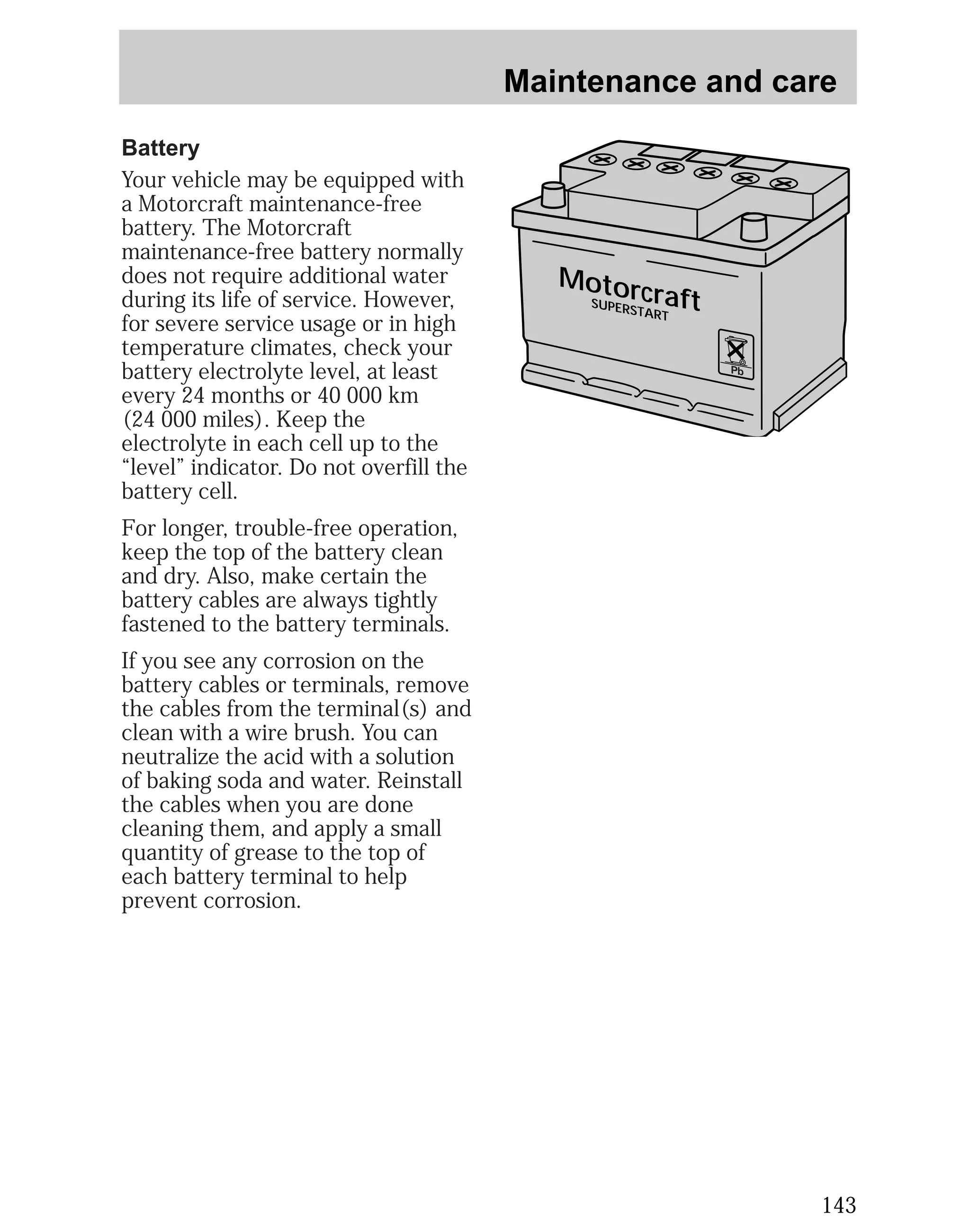
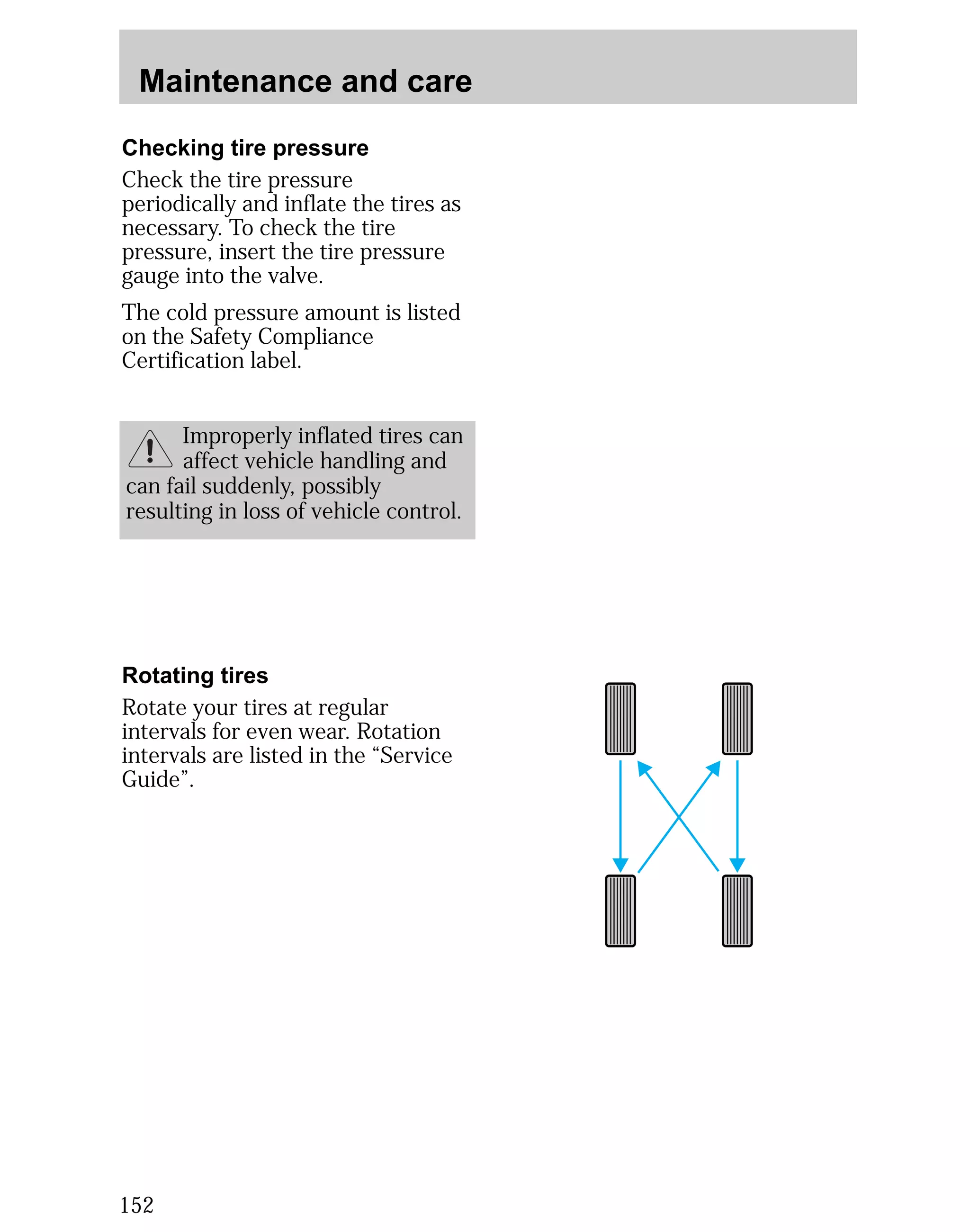
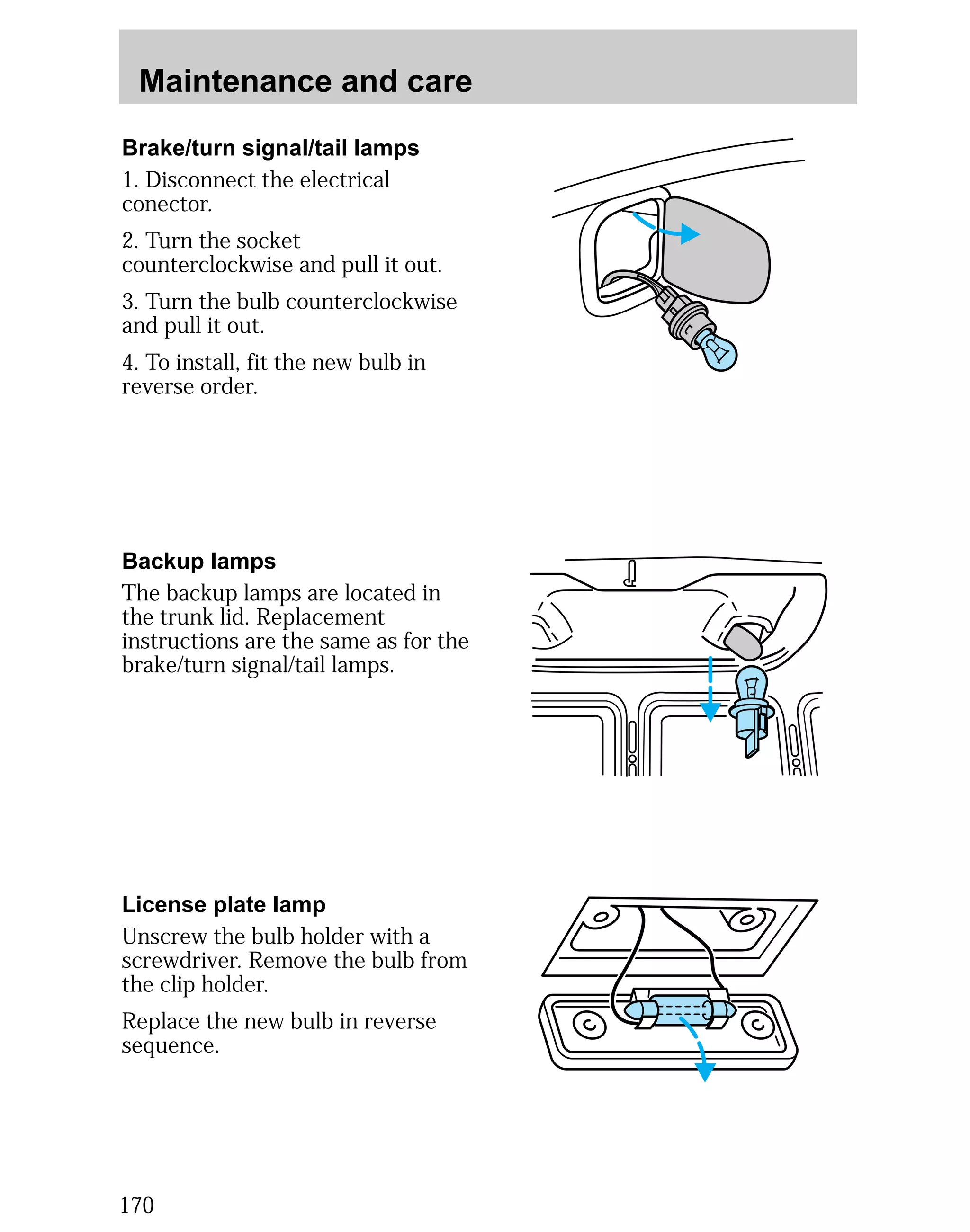
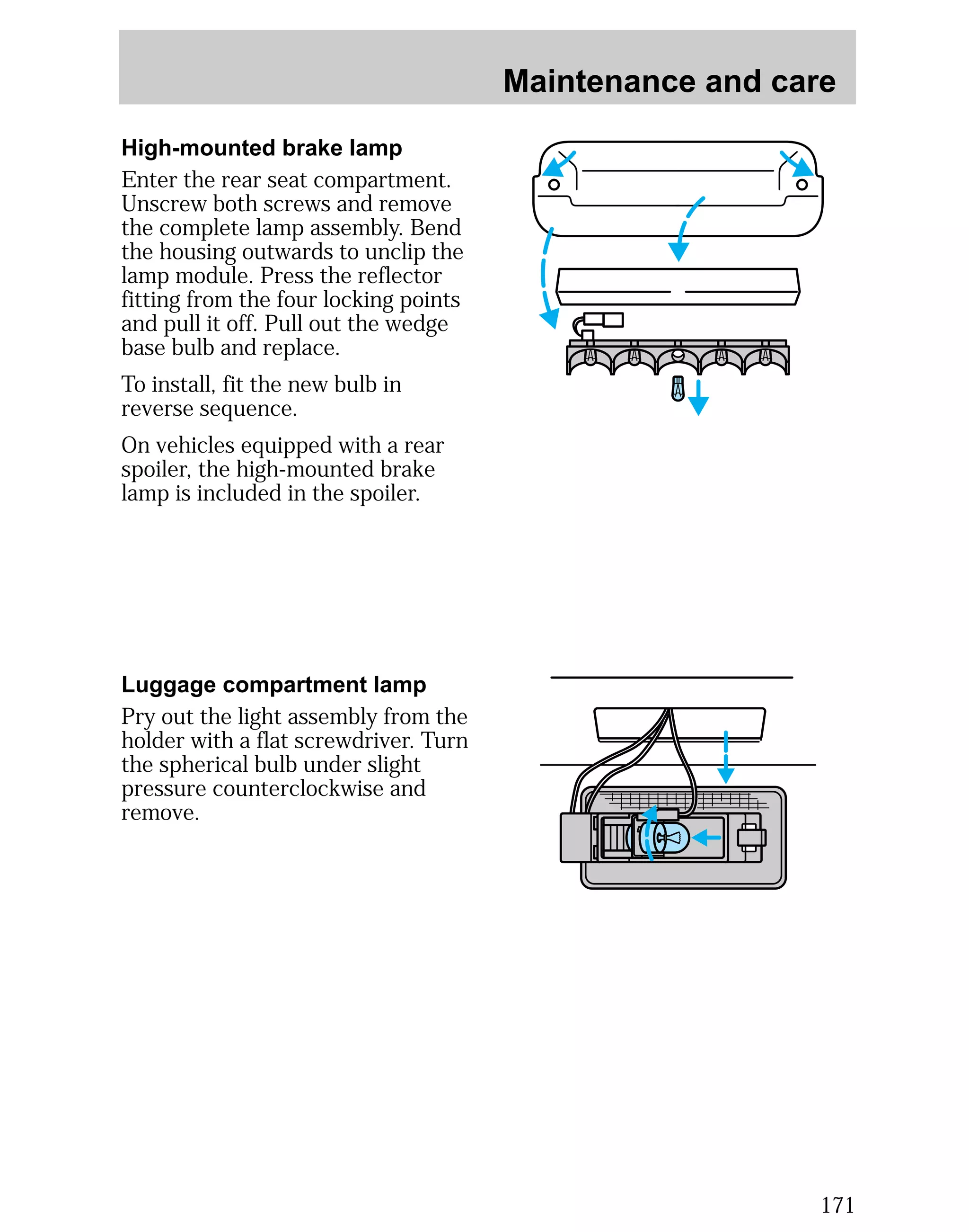
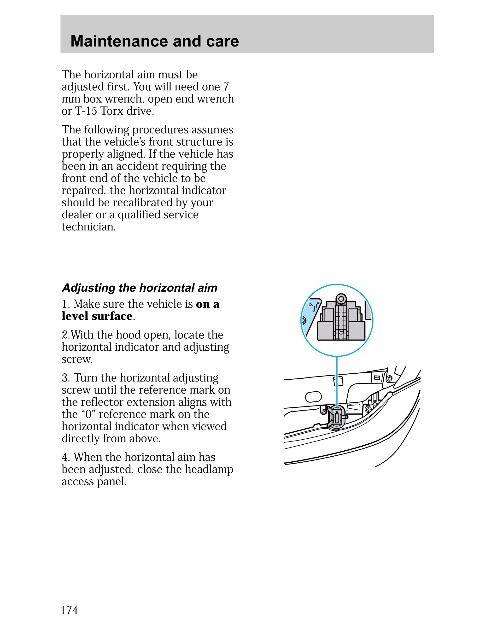
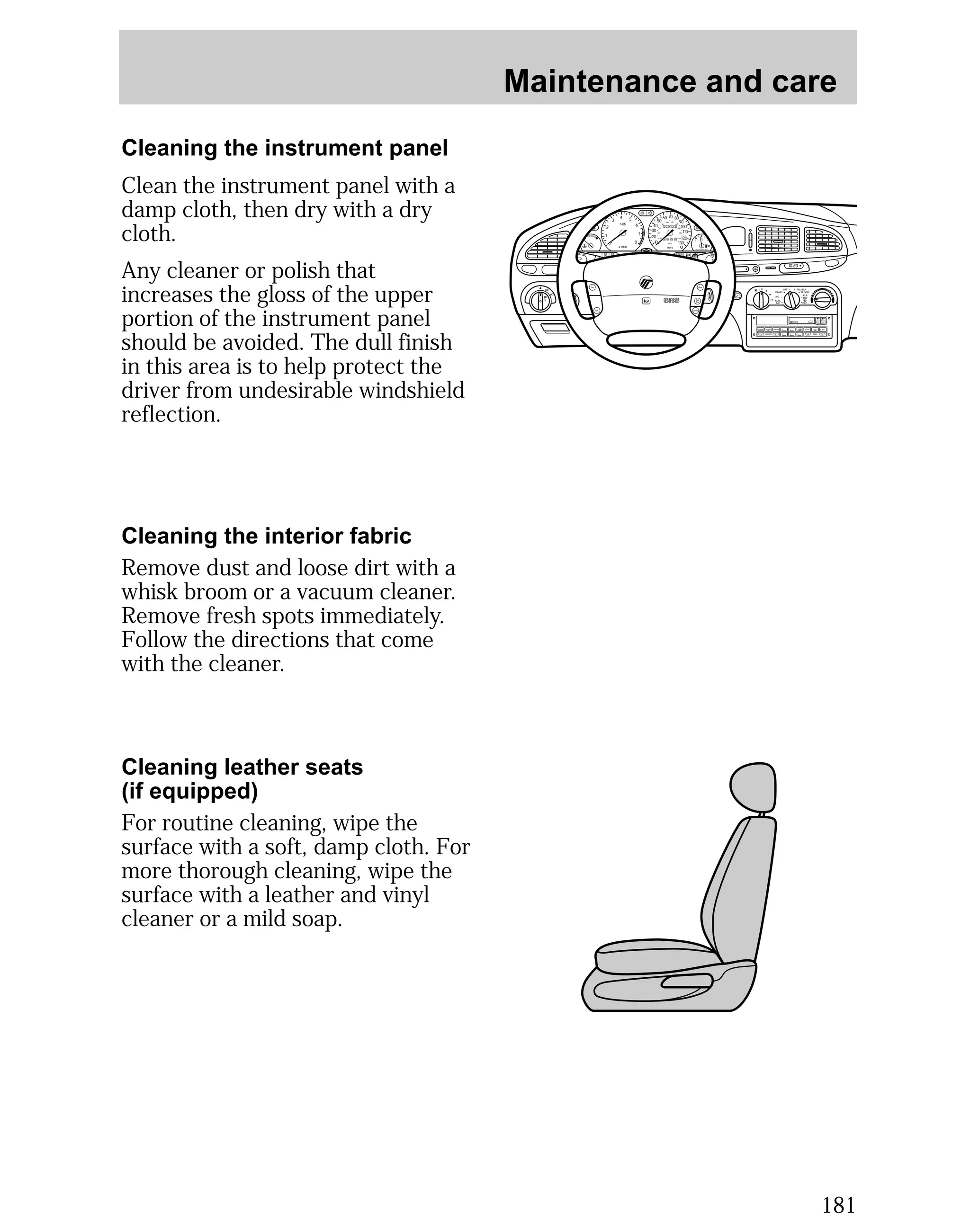
![Maintenance and care
137
When adding engine coolant
Ford recommends Ford Premium
Cooling System Fluid, which is an
optimized formula that will protect
all metals and rubber elastomers
used in Ford engines for four years
or 80 000 km (50 000 miles).
It is neither necessary nor
recommended to use supplemental
coolant additives in your gasoline-powered
vehicle. These additives
may harm your engine coolant
system.
When you change or add engine
coolant, it is important to maintain
engine coolant concentration
between 40% (-24°C [-11°F]) and
60% (-52°C [-62°F]), depending on
your local climate conditions.
A coolant concentration below 40%
will result in a loss of freeze
protection. A concentration above
60% may cause the engine to
overheat on a warm day.
Refer to Lubricant specifications
in the Capacities and
specifications chapter. Use only a
premium nationally-recognized
brand name engine coolant or
equivalent.](https://image.slidesharecdn.com/98mystique-140905151947-phpapp01/75/98-mystique-137-2048.jpg)

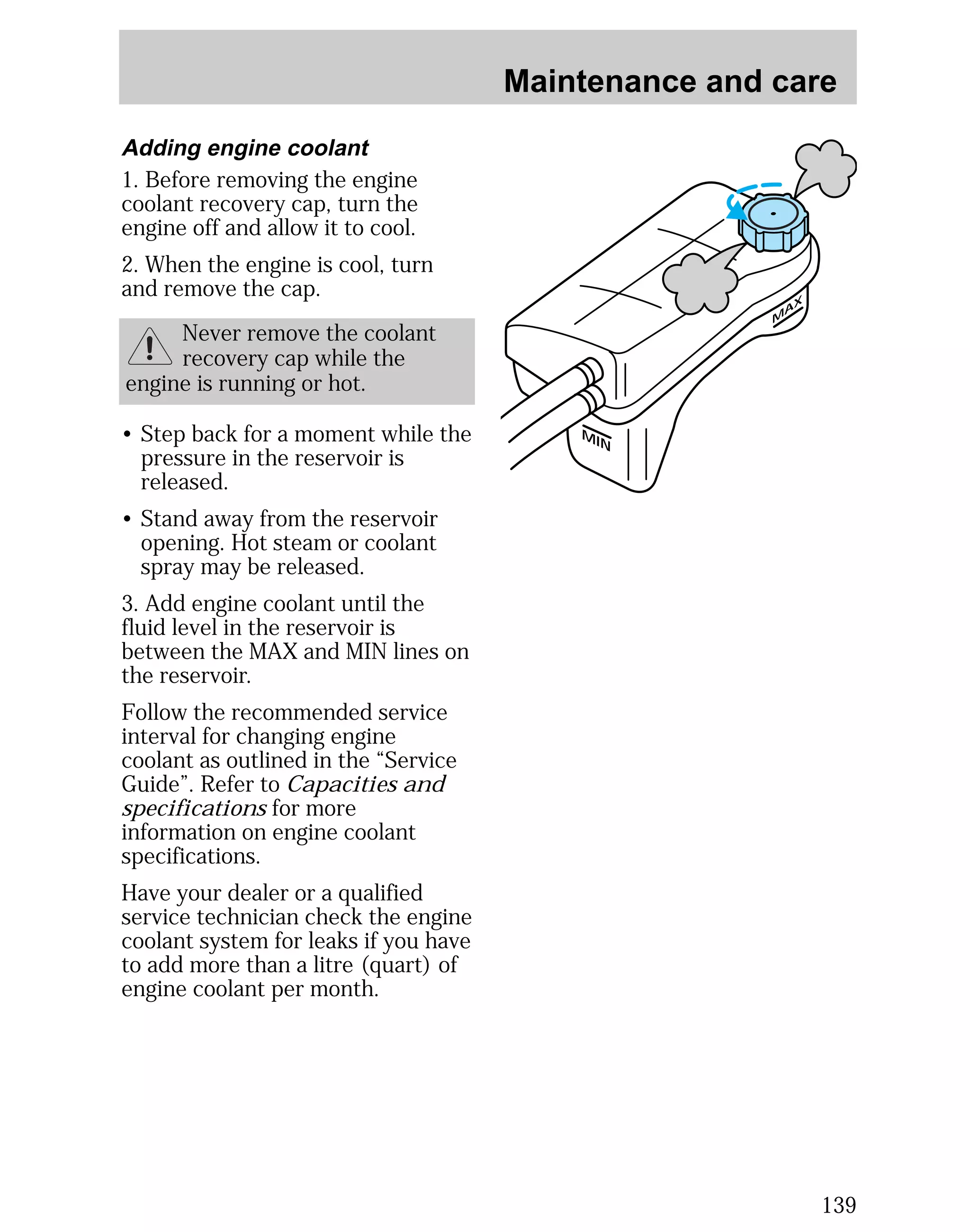
![Maintenance and care
Severe winter climate
If you drive in extremely cold
climates (less than -36°C [-34°F]),
it may be necessary to increase the
coolant concentration above 50%.
Refer to the chart on the coolant
container to ensure the coolant
concentration in your vehicle is
such that the coolant will not
freeze at the temperature level in
which you drive during the winter
months. Never increase the engine
coolant concentration above 60%.
Leave a 50/50 mixture of engine
coolant and water in your vehicle
year-round in non-extreme
climates.
Checking and adding power
steering fluid
Switch off the engine. With the
steering system at normal
operating temperature, the fluid
level should come up to the MAX
mark.
If the fluid level drops below the
MIN mark, add the specified fluid.
Refer to the Capacities and
specifications chapter.
140
MAX
MIN](https://image.slidesharecdn.com/98mystique-140905151947-phpapp01/75/98-mystique-140-2048.jpg)