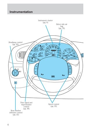
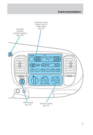
This document provides an overview of the instrumentation, controls, and features of a vehicle. It begins with introductory information and warnings before detailing each button, knob, and display found in the vehicle's interior. The remainder describes the function of each gauge and light on the instrument cluster. It also explains how to use the trip computer to view vehicle status information.
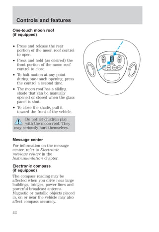
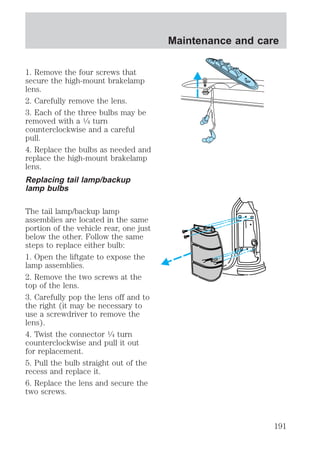
![2. Locate the compass module
mounted on the base of the mirror.
3. Insert an appropriate diameter
rod (paperclip) into the switch
access hole underneath the
compass module.
4. Gently press the switch for 2 to
4 seconds until CAL and a
direction are displayed on the trip
computer. (To exit CAL mode
before performing a compass
adjustment, turn the ignition OFF.)
5. Release pressure from the
switch.
6. Slowly drive the vehicle in a
circle (less than 5 km/h [3 mph])
until the CAL indicator turns off.
This will take up to five circles to
complete calibration.
7. The compass is now calibrated.
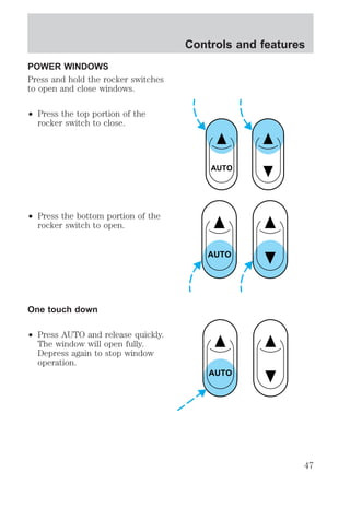
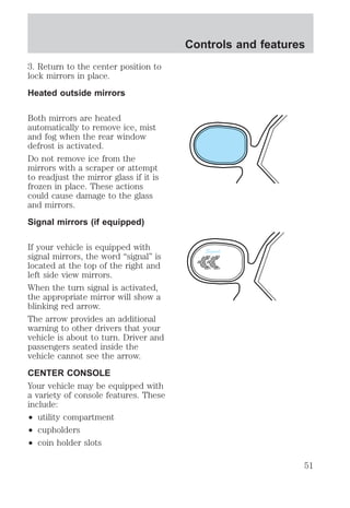
Power quarter rear windows
(if equipped)
Controls and features
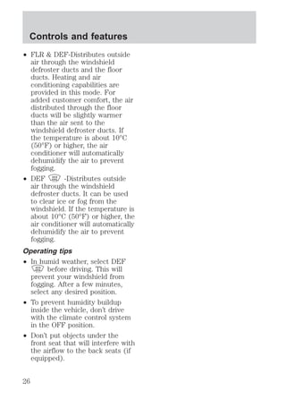
Press the portion of the VENT
control to open the power rear
quarter windows.
Press the portion of the VENT
control to close the power rear
quarter windows. RESET
VENT VENT
MODE E/M
45](https://image.slidesharecdn.com/98expedition-140905151937-phpapp01/85/98-expedition-45-320.jpg)
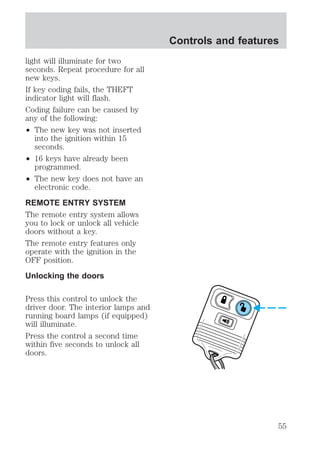
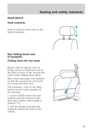
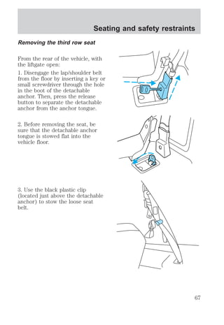
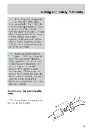
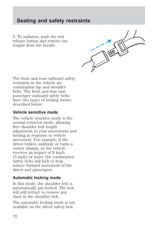
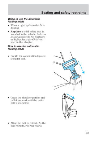
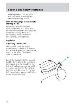
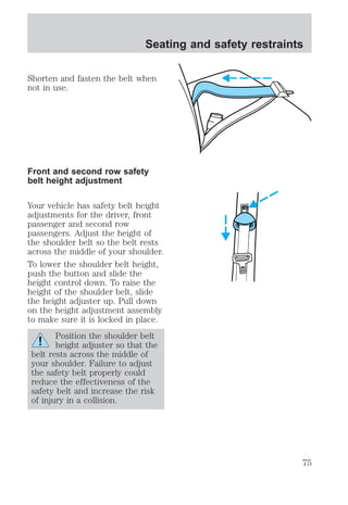
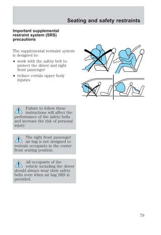
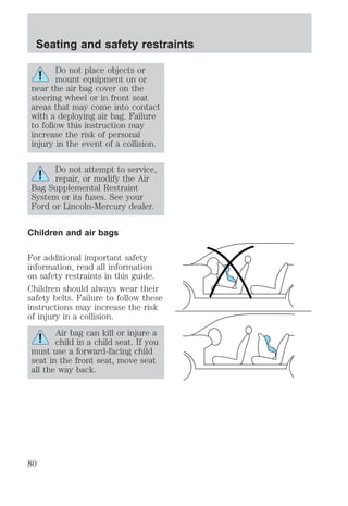
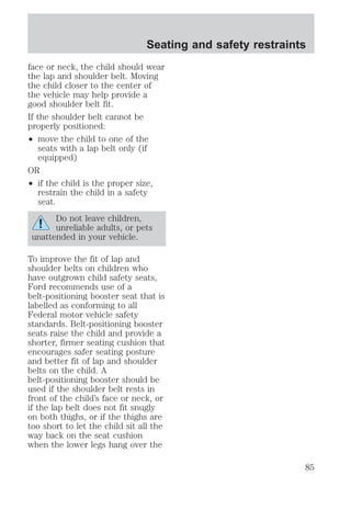
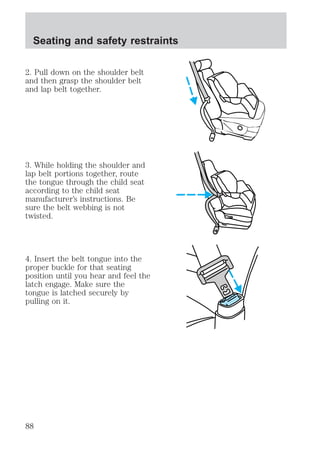
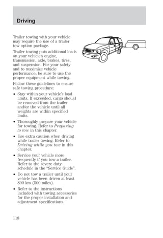
![Seating and safety restraints
younger and who weigh 18 kg
[40 lbs] or less), you must put
them in safety seats made
especially for children. Check your
local and state or provincial laws
for specific requirements regarding
the safety of children in your
vehicle.
Never let a passenger hold
a child on his or her lap
while the vehicle is moving. The
passenger cannot protect the
child from injury in a collision.
Always follow the instructions and
warnings that come with any infant
or child restraint you might use.
When possible, place children in
the rear seat of your vehicle.
Accident statistics suggest that
children are safer when properly
restrained in the rear seating
positions than in the front seating
position.
Children and safety belts
Children who are too large for
child safety seats (as specified by
your child safety seat
manufacturer) should always wear
safety belts.
Follow all the important safety
restraint and air bag precautions
that apply to adult passengers in
your vehicle.
If the shoulder belt portion of a
combination lap and shoulder belt
can be positioned so it does not
cross or rest in front of the child’s
84](https://image.slidesharecdn.com/98expedition-140905151937-phpapp01/85/98-expedition-84-320.jpg)
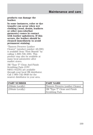
![may void your warranty of your
vehicle’s engine cooling system.
Recycled engine coolant
Ford Motor Company recommends
that Ford and Lincoln-Mercury
dealers use recycled engine
coolant produced by
Ford-approved processes. Not all
coolant recycling processes
produce coolant which meets Ford
specification ESE-M97B44–A, and
use of such coolant may harm
engine and cooling system
components.
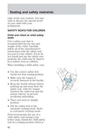
Always dispose of used
automotive fluids in a responsible
manner. Follow your community’s
regulations and standards for
recycling and disposing of
automotive fluids.
Coolant refill capacity
To find out how much fluid your
vehicle’s cooling system can hold,
refer to Refill capacities in the
Capacities and specifications
chapter.
Have your dealer check the engine
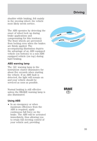
cooling system for leaks if you
have to add more than a liter
(quart) of engine coolant per
month.
Severe winter climate
If you drive in extremely cold
climates (less than –36°C [–34°F]),
it may be necessary to increase the
coolant concentration above 50%.
Refer to the chart on the coolant
Maintenance and care
161](https://image.slidesharecdn.com/98expedition-140905151937-phpapp01/85/98-expedition-161-320.jpg)
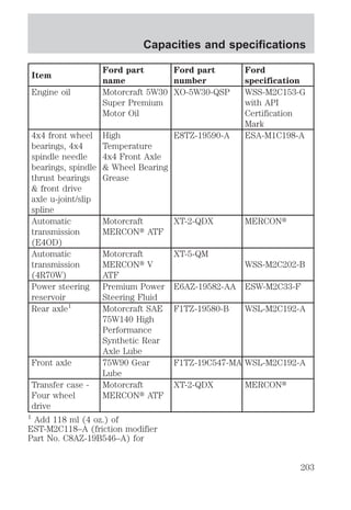
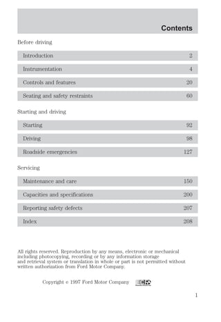
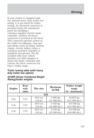
![Capacities and specifications
chapter.
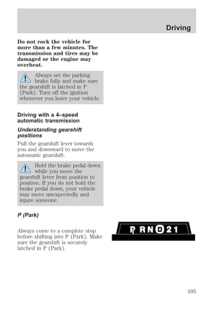
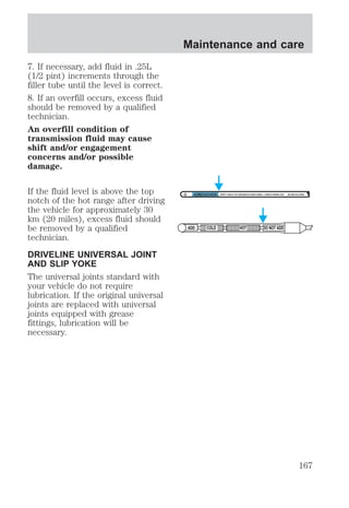
An overfill condition of
transmission fluid may cause
shift and/or engagement
concerns and/or possible
damage.
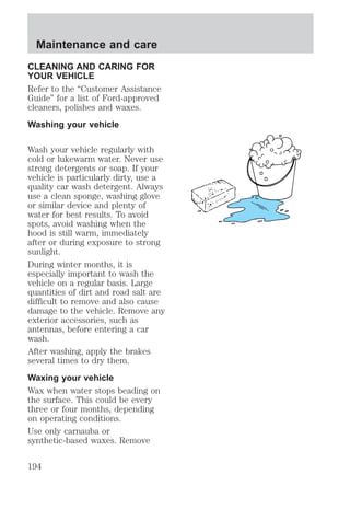
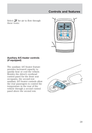
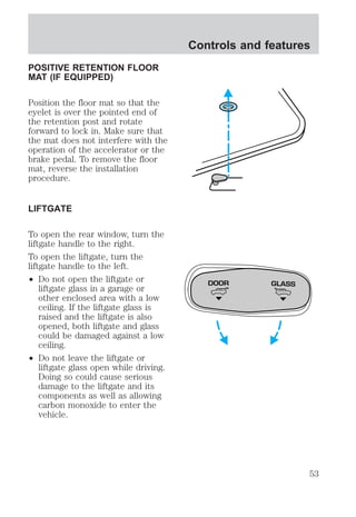
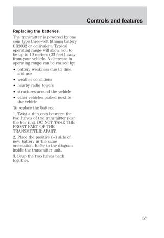
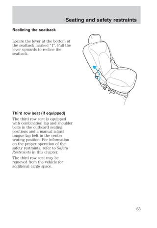
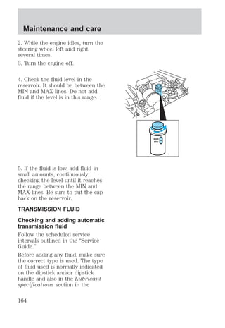
Do not drive the vehicle if the fluid
level is below the hole at the
bottom of the blade type dipstick
(4R70W transmission) or below
the COLD area on the bullet type
dipstick (E4OD transmission) and
outside temperatures are above
10°C (50°F) (see figure to the
right).
Your transmission does not use up
fluid. However, it is recommended
that you check the transmission
fluid at least twice a year. The
fluid level should be checked if the
transmission is not working
properly, i.e., if the transmission
slips or shifts slowly or if you
notice some sign of fluid leakage.
Transmission fluid should be
checked at normal operating
temperatures 66°C-77°C
(150°F-170°F) on a level surface.
The normal operating temperature
can be reached after approximately
32 km (20 miles) of driving.
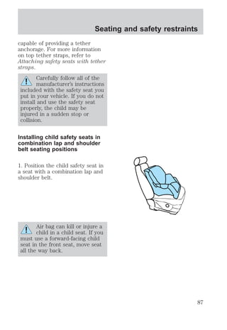
The transmission fluid should be in
this range if at normal operating
temperature (66°C-77°C
[150°F-170°F]) (see figure to the
right).
Maintenance and care
DON'T ADD IF IN CROSSHATCHED AREA • CHECK WHEN HOT IDLING IN PARK
ADD COLD HOT DO NOT ADD
DON'T ADD IF IN CROSSHATCHED AREA • CHECK WHEN HOT IDLING IN PARK
ADD COLD HOT DO NOT ADD
165](https://image.slidesharecdn.com/98expedition-140905151937-phpapp01/85/98-expedition-165-320.jpg)
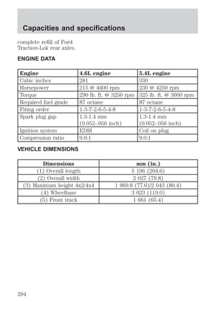
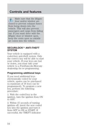
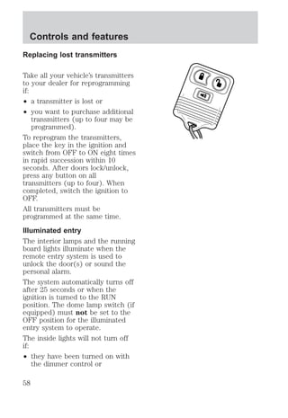
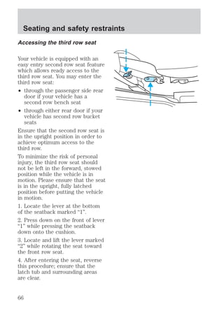
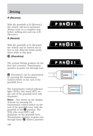
![The transmission fluid should be in
this range if at room temperature
(10°C-35°C [50°F-95°F]) (see
figure to the right).
If your vehicle has been operated
for an extended period at high
speeds, in city traffic during hot
weather or pulling a trailer, the
vehicle should be turned off for
about 30 minutes to allow the fluid
to cool before checking.
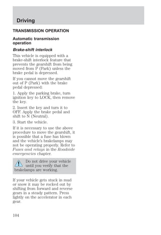
1. Park the vehicle on a level
surface and engage the parking
brake.
2. With the parking brake engaged
and your foot on the brake pedal,
start the engine and move the
gearshift lever through all of the
gear ranges. Allow sufficient time
for each gear to engage.
3. Latch the gearshift lever in P
(Park) and leave the engine
running.
4. Remove the dipstick, wiping it
clean with a clean, dry lint free
rag.
5. Install the dipstick making sure
it is fully seated in the filler tube.
6. Remove the dipstick and inspect
the fluid level. The fluid level
should be in the crosshatched area
on the dipstick.
DON'T ADD IF IN CROSSHATCHED AREA • CHECK WHEN HOT IDLING IN PARK
ADD COLD HOT DO NOT ADD
P R N D 2 1
Maintenance and care
166](https://image.slidesharecdn.com/98expedition-140905151937-phpapp01/85/98-expedition-166-320.jpg)
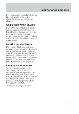
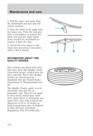
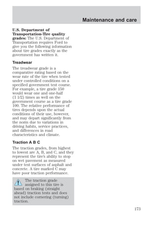
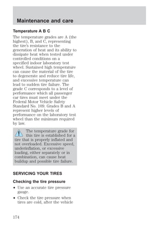
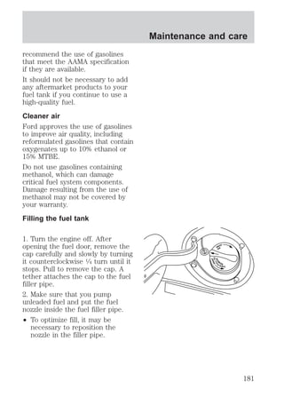
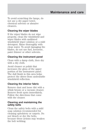
![Maintenance and care
² To help reduce early nozzle shut
off and fuel spillage, park your
vehicle so the fuel filler door is
level.
² Avoid excessively fast fuel
dispensing rates (over 38 L
[10 gallons] per minute).
² If you spill fuel on the body of
your vehicle, clean it off
immediately. The fuel may dull
or soften the paint if it is not
washed off promptly.
² To replace the fuel cap, align
the tabs on the cap with the
notches on the fuel filler pipe.
Turn it clockwise until it stops.
² Push the fuel door closed.
If the check engine warning light
illuminates and remains illuminated
while the engine is started, the
fuel cap may not be properly
seated. Turn off the engine,
remove the fuel cap and replace it,
being sure to align the cap
properly.
If the cap is lost, replace it with an
authorized Motorcraft or equivalent
part.
Calculating fuel economy
To accurately calculate your
vehicle’s fuel economy:
1. Fill the tank completely and
record the initial odometer
reading.
2. Each time you fill the tank,
record the amount of fuel added
(in liters or gallons).
182](https://image.slidesharecdn.com/98expedition-140905151937-phpapp01/85/98-expedition-182-320.jpg)