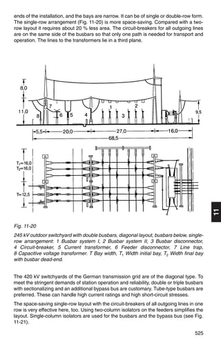
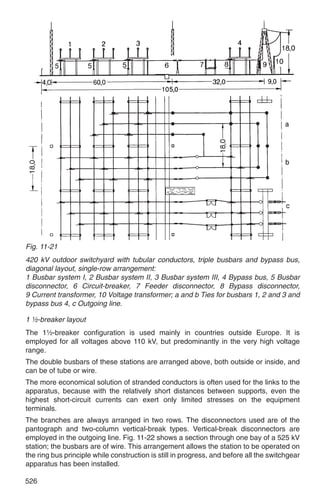
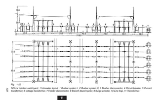
This document discusses requirements and guidelines for outdoor switchgear installations, including:
1) Minimum clearances and safety distances between live parts must follow standards like DIN VDE 0101. Clearances may need to increase based on conditions like high altitudes.
2) Equipment is selected based on the maximum operating voltage and environmental conditions, including air pollution which can lead to flashovers on insulators.
3) Cable trenches are used to lay cables underground and follow access roads. They have cable supports, drainage, and openings to equipment. Perimeter fencing and protective screens are also required.
Industrial Training at Howrah 220 kV Substation.Avirup Ghosh
The document describes a presentation by four electrical engineering students on their vocational training at the Howrah 220 kV substation. It provides an overview of the substation, including its main components such as transformers, transmission lines, and protective equipment. It also discusses the roles and specifications of key elements within the substation, such as circuit breakers, insulators, and instrument transformers.
This document provides an overview of substations, including their classification, components, and grounding practices. It defines a substation as a place where voltage is transformed from high to low levels using transformers. Substations are classified by voltage level (e.g. EHV, HV, MV, LV), configuration (outdoor vs indoor), and type (conventional vs gas insulated). The document outlines the typical components of a substation and best practices for proper grounding to ensure reliability, safety, and trouble-free operation.
This document provides an outline and overview of a presentation on the 220kV GSS substation in Renwal, Jaipur. It discusses the key equipment used in substations including transformers, circuit breakers, isolators, instrument transformers, bus bars, protective relays, lightning arrestors, and capacitive voltage transformers. It also describes the layout of the 220kV GSS substation which has a panel section containing control and relay panels, and a switchyard section containing the 220kV, 132kV and 33kV equipment.
This document provides an overview of the components and equipment found at a 220 KV substation in Sanganer, Rajasthan, India. It discusses the purpose and basic functions of key items such as the yard, bus bar system, lightning arrestors, wave traps, isolators, instrument transformers including current and potential transformers, and power transformers. The document also provides brief descriptions of the incoming and outgoing feeders at this particular 220 KV substation and includes diagrams of some of the major equipment.
1. Substations are facilities that link power generation stations to transmission systems and distribution systems by increasing or decreasing voltage levels through transformers.
2. Key components of substations include power transformers, current and potential transformers, circuit breakers, isolators, earth switches, lightning arrestors, and wave traps.
3. Power transformers increase or decrease voltage to allow for efficient transmission of power over long distances and distribution to customers, while current and potential transformers adapt measurements to instrumentation.
A private company is building a new factory requiring 1150 kVA of power. The company will connect to a 36 kV distribution network with a short circuit current of 15.3 kA and rated operational current of 525 A at 31.5 kV. A new indoor transformer substation will include a load break switch incoming feeder, circuit breaker outgoing feeder, circuit breaker for customer isolation and protection, metering cubicle, and transformer protection cubicle with circuit breaker. The transformer will be selected as 1600 kVA, 31.5/0.4 kV based on the power requirements. A single line diagram of the substation will be drawn showing all equipment ratings.
The document provides information about:
[1] Training conducted at the 220 KV Grid Sub Station in Sanganer, Jaipur, Rajasthan by Kumar Mayur Sinha for his B.Tech in Electrical Engineering.
[2] Details about the Rajasthan Rajya Vidyut Prasaran Nigam Limited (RRVPNL), the company that owns and operates the substation.
[3] An overview of the 220 KV Sanganer substation, including its installation of 7 transformers with a total capacity of 312.5 MVA to step down electricity from 220KV to 132KV and lower voltages.
This document provides an overview of a 220kV grid substation in Kishangarh Bas, Rajasthan, India. It contains two incoming 220kV feeders and seven outgoing 132kV and 33kV feeders. The substation consists of a yard and administration room. The yard contains two 100MVA power transformers, circuit breakers, isolators, current and potential transformers, lightning arrestors, and bus bars. The administration room houses equipment like batteries to provide backup DC power. The document describes the various equipment and their functions.
This document provides an overview of a 220/66kV substation in Punjab, India. It discusses the key components and functions of the substation, including transformers, circuit breakers, busbars, insulators, overhead lines, and protection equipment. The substation steps down electricity from 220kV to 66kV for distribution. It also discusses the roles and specifications of important equipment like current transformers, potential transformers, conductors, and capacitor banks.
This document provides an overview of grid substations. It discusses how substations receive power from generating stations and transmission lines and transform voltages to suitable levels for distribution. It also describes the key components of substations, including transformers, circuit breakers, and earthing systems. Classification of substations by voltage level and indoor/outdoor design is covered. The purpose and components of transmission lines, including conductors, insulators, towers, and earth wires, are summarized as well.
The document discusses the functions and types of equipment used in electrical distribution substations. It provides descriptions of common substation equipment such as power transformers, circuit breakers, disconnecting switches, bus bars, current and potential transformers, capacitors, reactors, protective relays and batteries. It also provides examples of how to calculate primary and secondary currents in transformers of different ratings and briefly discusses some common bus schemes used in Pakistan.
This document provides a summary of a presentation on summer training at the 220kV GSS in Hinduan City. The substation steps down incoming power transmission voltages of 220kV to 132kV and 132kV to 33kV to supply consumers. It has 3 incoming 220kV lines and supplies power to various 132kV and 33kV feeders. The presentation describes the various equipment used at the substation like transformers, circuit breakers, isolators, protective relays, conductors, and insulators. It also discusses maintenance procedures and fault operations.
A pole mounted substation is an outdoor electrical equipment that steps down high voltage power for distribution to residential and commercial customers. It connects to an 11kV line through a gang isolator and horn gap fuses. A transformer then steps down the voltage to 415V for customers. An oil circuit breaker automatically isolates the transformer from customers in the event of a fault. Pole mounted substations are generally used for transformer capacities up to 200kVA and provide power for applications like private homes, agriculture, wind farms, and rural electrification.
The document provides information on substation planning criteria and design, including:
1. The maximum fault level on any new substation bus should not exceed 80% of the rated rupturing capacity of circuit breakers.
2. Studies such as load flow, short circuit, and transient stability are performed to establish design criteria.
3. Key factors in substation arrangement and layout include system security, operational flexibility, simplicity of protection, ability to limit short circuits, maintenance facilities, and ease of expansion.
WBSETCL Subhash Gram 220KV Substation Training ReportArijit Basu
The document summarizes the Subhash Gram 220 KV substation operated by WBSETCL. It receives power at 220 KV from a nearby PGCIL substation, steps it down through transformers, and distributes it to nearby substations and customers. Key components include two 160 MVA 220/132/33 KV transformers, various circuit breakers, isolators, buses, and protection/metering equipment like CTs and CVTs. The substation layout includes separate switchyards for the 220 KV, 132 KV and 33 KV voltage levels.
This document summarizes a 220kV substation in Kanpur, India. It has three main sections: a panel section containing control panels and relay panels, a switchyard containing components like circuit breakers and transformers, and a battery room. The substation receives 220kV power from two incoming lines and steps it down to 132kV and 33kV for outgoing distribution lines. It uses transformers to convert between voltages and buses to distribute power. Key terms like tripping, shutdown, and breakdown are also defined relating to power disruptions and maintenance.
This document provides an index and overview of the layout of a substation.
1. The index lists 14 topics that will be covered, ranging from bus bars and isolators to transformers and circuit breakers.
2. The introduction explains that electric power is transmitted through a network of substations, which change characteristics of the electric supply like voltage.
3. Outdoor substations like the 220KV GSS Sanganer are described, which have one and half breaker schemes and feed power to locations like KTPS and Sakatpura.
The document is a presentation on the Liluah 132/33/25 KV substation in West Bengal. It includes acknowledgments, a single line diagram of the substation, and sections covering various equipment found at the substation like electrical busbars, protective relay schemes, lightning protection, isolators, capacitor banks, powerline carrier communication, batteries, earth transformers, traction transformers, station service transformers, and power transformers. Technical specifications are provided for some of the major equipment.
It is Multimedia presentation made by Abdul Samad, An Electrical Engineer From UET Lahore Pakistan. For queries contact Abdulsamad.pisces@hotmail.com
Hope u find it useful
1. An electric power substation is a facility used to transform electricity from high to low voltage or vice versa for transmission or distribution. It contains equipment like transformers, circuit breakers, and switches.
2. Substations are used to connect generators and transmission lines, transform power between voltage levels, interconnect power sources, switch connections, control voltage and power flow, and detect and respond to faults on the system.
3. They are classified by their main function as transmission substations for high voltages or distribution substations for low voltages. Transformer substations contain transformers while switching substations focus on connections.
The document provides an overview of a power substation (switchyard) including:
- Typical components including busbars, circuit breakers, current transformers, and surge arrestors.
- Explanations of switchyard equipment such as circuit breakers, isolators, earth switches, and their functions.
- Descriptions of different types of substations based on voltage levels and mounting structures.
- Brief explanations of additional equipment such as capacitive voltage transformers, wave traps, and post insulators.
This document summarizes a seminar presented by an electrical engineering student on their practical training at a 220KV substation. It includes an introduction to substations and their components like transformers, circuit breakers, bus bars, and protective relays. It also provides details on the specific 220KV substation visited, including its outgoing feeders and a single line diagram. The control room and conclusion of the seminar are also briefly mentioned.
this ppt gives u a clear idea about substations ..there are two types of substation
1) air insulated substations
2) gas insulated substations
this ppt is about air insulated substations and gas insulated substations
This document summarizes a seminar presented on practical training at a 220kV substation. It includes an introduction to the substation and descriptions of its key components like transformers, circuit breakers, current transformers, lightning arrestors, capacitors and the control room. Diagrams of the substation's single line diagram are also included. The conclusion states that the training provided insight into real instrumentation used at substations and how they are operated and managed.
This document provides a report on the 400/220 KV Nelamangala power station near Bangalore, India. It includes a single line diagram of the substation, details of the bus bar scheme, and descriptions of the main equipment including capacitive voltage transformers, current transformers, circuit breakers, isolators, transformers, and reactors. It also covers substation auxiliaries, control rooms, earthing systems, and provides specifications for the main transformers. The power station was established to integrate new power sources into the southern grid and reduce grid failures in the region.
This document provides an overview of the author's summer training at the 132kV GSS Chambal power house in Jaipur, Rajasthan. It discusses the introduction of RVPN, site selection criteria for GSS, equipment used including transformers, CVTs, isolators, circuit breakers, and protection relays. Diagrams of the single line diagram, control room, transformer, and relay working are also included. The training improved the author's understanding of electrical power transmission and the practical differences compared to theoretical knowledge.
The document discusses the installation of metering systems at distribution transformer centers (DTCs) to monitor energy usage. Key details include:
- DTC metering provides insight into transformer health and helps analyze issues like load imbalance, voltage imbalance, and transformer utilization.
- Meters being installed are 3-phase 4-wire types with 0.5 accuracy class that measure voltage, active power, apparent power and power duration on each phase.
- The installation process involves selecting sites, installing meters and current transformers (CTs), connecting potential transformers (PTs), and laying control cabling with proper demarcation.
- Testing and data collection is done to verify installations, with data analysis to check for
The document discusses the design of power substations. It defines a substation as an assembly of apparatus used to change characteristics of electrical supply like voltage, frequency, and power factor. It notes substations receive high voltage energy from generating stations and reduce the voltage for local distribution while providing switching facilities. The document covers classification of substations by service requirement and constructional features. It also describes common substation equipment, auxiliaries, and considerations for designing substations.
The following topics will be covered: the definition of a substation, an overview of the different type of substations and the functions of substations
This document provides details about a practical training report submitted by Srijan Tripathi at the 220KV Grid Substation in Allahabad, Uttar Pradesh, India. It includes an introduction to the Uttar Pradesh Power Transmission Corporation Limited, which is responsible for electricity transmission and distribution across Uttar Pradesh. It also describes the key equipment housed at the 220KV grid substation, including transformers, circuit breakers, insulators, control panels, and more. The report contains chapters on each major component, diagrams, tables, and serves to document Srijan Tripathi's work and training completed at the substation.
This document provides information about the construction, components, testing, operation, protection and maintenance of a 132kV switchyard. It includes details about the bus bars, circuit breakers, current transformers, potential transformers, wave traps, isolators, control and protection schemes. The key components of the switchyard are described along with their ratings and testing procedures. The operational modes and protection philosophy are also summarized.
Training from 220kv GSS Sanganer, which is located on Muhana Road, JaipurR-One Power
The technology all about GSS System and their operating system.
In the presentation all about the GSS and their instrument which has used in GSS for operation and controlling the whole system.
I hope this presentation helpfull to all those students, who had their training from Sanganer 220kv GSS.
This document discusses various busbar arrangements used in substations including:
- Single busbar system
- Single bus with sectionaliser system
- Double busbar system
- One and half breaker system
It provides diagrams and explanations of how each system works, their advantages and disadvantages. It also discusses the different busbar configurations adopted by the Andhra Pradesh Transmission Corporation (APTRANSCO) at various voltage levels.
This document discusses high voltage substation design, applications, and considerations. It provides an overview of substation basics, electrical configurations, physical design, protection and controls, and coordination of design and construction. The presentation covers typical substation voltage levels, configurations such as ring bus and breaker-and-a-half, factors to consider in the design process such as service conditions and studies required, and reliability comparisons of different configurations. Design guidelines for spacing and clearances are also presented.
This document is a project report on relays by Sheshadri Shekhar Rauth for his Bachelor of Technology degree in Electrical Engineering. It discusses the history and holding capacity of Diesel Loco Shed in Kharagpur, the basic design and operation of relays, and the types of relays used in the shed including wheel slip relays, general purpose relays, and contactor relays. It also provides references and concludes that the training opportunities at the shed were helpful for gaining knowledge about machinery and instruments.
Relays sense abnormal voltage and current conditions and send signals to circuit breakers to isolate faulty parts of a power system. Electromagnetic induction relays use eddy currents produced in a disc to generate torque. There are different types of overcurrent and directional relays. Distance relays use impedance, reactance, or mho principles. Transformer and feeder protection uses overcurrent, distance, or pilot wire schemes. Circuit breakers use oil, air, sulfur hexafluoride, or vacuum to extinguish arcs and open faulty circuits. Instrument transformers reduce high voltages and currents to safer, measurable levels for meters and relays.
This document discusses power system protection settings and provides information on calculating protection settings. It covers the functions of protective relays and equipment protection, the required information for setting calculations such as line parameters and fault studies, and the process of calculating, checking, and implementing protection settings. The goal is to set protections to operate dependably, securely, and selectively during faults while meeting clearance time requirements.
A substation is an important part of an electrical power system where voltage is transformed from high to low levels or vice versa. Electric power may pass through multiple substations between generation and consumption. Main components of a substation include transformers to step up or down voltages, circuit breakers, switches, protective relays, surge arrestors, and other equipment. Substations can be indoor, outdoor, underground or pole-mounted depending on construction, and serve purposes like transmission, distribution, power factor correction or frequency changing. Careful consideration is given to site selection, environmental factors and layout of a substation.
The document discusses various components of power distribution systems including substations, transmission lines, and distribution lines. It provides details on:
1) The components of a pole mounted substation, including the pole structure, transformer, insulators, switches, and earthing equipment.
2) The components of lattice steel transmission towers, including the peak, cross arms, body, and foundation.
3) Types of insulators used in distribution systems, including pin, post, disc, and suspension string insulators.
Overhead ground wires (OHGWs) are wires installed above power lines to protect them from lightning and distribute ground potential. They are grounded at every transmission structure. OHGWs use high-strength galvanized steel wire and must have the same sag as the power line conductors. Insulators are used to support power lines and provide clearance between lines and structures. Common insulator types include pin, suspension, and strain insulators made of porcelain, glass or fiberglass. Suspension insulators consist of interlinking disks used in strings, with more disks needed at higher voltages.
The document discusses busbars, which are the backbone of low voltage switchgear assemblies. It covers topics such as busbar material selection criteria, sizing calculations, installation practices, and good practices for bending, punching holes, making connections, and applying anti-corrosion treatments. Key factors in busbar selection include rated current, short circuit withstand capability, ambient temperature, and enclosure protection level. Proper sizing ensures correct operation without overheating.
This document provides an overview of domestic wiring concepts including electrical supply systems, distribution systems, cable types and ratings, load types, protection devices like fuses and circuit breakers, earthing, and general installation requirements. The three-phase four-wire distribution system is described along with voltage tolerances and cable sizing factors like voltage drop. Resistive, inductive, and capacitive load characteristics are summarized. Protection devices like fuses, MCBs, RCCBs, and ELCBs are explained with their working principles and advantages.
This document discusses transmission line parameters and components. It covers:
- The major components of transmission lines including conductors, towers, earth wires, and insulators.
- Types of transmission lines such as overhead lines, underground cables, and their classifications.
- The four parameters that characterize transmission lines: resistance, inductance, capacitance, and conductance.
- Factors that influence resistance like skin effect, temperature, conductor material, and bundling.
This document provides a list of materials and specifications for an electrical installation project. It includes 14 items with descriptions of materials like service entrance caps, feeder conduit, conductors, emergency circuit breakers, distribution panels, switches and more. Specifications are provided for proper installation and sizing according to standards like the Philippine Electrical Code (PEC) 2017. Total estimated cost is provided for each item and annexes provide additional details for specifications referenced.
This document provides information on electrical wiring systems. It discusses single phase and three phase wiring systems used for domestic and industrial applications. It describes the components of wiring including switches, wires, cables and different types. Factors affecting choice of wiring and specifications of wires are explained. Common wiring methods like cleat wiring, wooden casing and capping wiring, CTS wiring are described along with their advantages and disadvantages.
Transmission & distribution of electrical powerpriyanka1432
This document provides an overview of the course "Transmission & Distribution of Electrical Power" which is divided into 8 modules. Module I introduces basics of power transmission including the necessity of transmitting electricity over long distances at high voltages to reduce losses. It also covers classifications of different transmission systems. Subsequent modules cover components of transmission lines such as conductors, insulators, and their characteristics as well as transmission line parameters and performance. Later modules address extra high voltage transmission, distribution system components, underground cables, and substations.
The document provides guidance on terminating shielded cable, stripping jacket from shielded cable, grounded and ungrounded shield termination procedures, and pigtail shield termination methods. It also discusses grounding and bonding requirements, including proper bonding jumper installations, corrosion prevention, and creepage distance. The document provides specifications for connectors, splicing, lacing, ties, and proper wiring routing.
Chapter 4 mechanical design of transmission linesfiraoltemesgen1
This chapter discusses the mechanical design of transmission lines. It covers various topics such as types of conductors, line supports, spacing between conductors, and sag-tension calculations. The key conductors mentioned are copper, aluminum, and steel. Wooden poles, steel tubular poles, reinforced concrete poles, and steel towers are described as the main types of line supports. The document also discusses the effects of wind and ice loading on transmission lines. Sag-tension calculations are explained using catenary curve equations.
This is the simple ppt explaining about the main components of the power systems. especially we are determining the insulators and its types with real time pictures which are attractive,
The document discusses ampacity, which is the maximum current a conductor can carry continuously without exceeding its temperature rating. It provides examples of calculating ampacity for different wire types and sizes, and factors like ambient temperature that require applying a correction factor. It also contains practice problems testing understanding of identifying wire sizes and types based on their ampacity, temperature ratings, and common applications.
Transmission lines have four parameters that characterize them: resistance, inductance, capacitance, and conductance. These distributed parameters determine the power carrying capacity and voltage drop across the line. Short lines only consider the series resistance and inductance, while medium and long lines must also account for the distributed shunt capacitance. The resistance of overhead transmission lines is affected by factors like skin effect, temperature, bundling of conductors, and proximity effect between phases.
This document discusses sizing underground power cables using MATLAB. It provides background on factors that affect cable sizing like voltage, current, power rating, cable properties, installation conditions, and permissible voltage drop. The general sizing methodology is described in 4 steps: 1) Gather data on the cable and load, 2) Determine minimum size based on continuous current capacity, 3) Determine minimum size based on voltage drop considerations, 4) Select highest size from steps 2 and 3. Tables provide example cable current and impedance ratings. Derating factors are discussed for installation conditions like temperature and cable grouping. A MATLAB code is developed to calculate cable cross-sectional area based on parameters and voltage drop limits.
The document discusses the key elements of transmission systems including:
- Transmission lines carry bulk power over long distances at high voltages from generating stations to substations.
- Standard transmission voltages include primary (110kV-400kV) and secondary (66kV-33kV).
- Distribution then moves power from substations to consumers at lower voltages like primary (33kV-11kV) and secondary (400V/230V).
- Transmission can be overhead via towers and conductors or underground via insulated cables. High voltage direct current (HVDC) and high voltage alternating current (HVAC) are the main types of transmission.
The document discusses cable selection and wiring systems. It describes the components of cables including conductors, insulation, sheathing, armouring, and types. Factors that influence cable sizing are discussed such as current rating, ambient temperature, installation conditions, and protective device rating. The proper method for calculating cable size is outlined in eight steps. Guidelines for selecting the size of conduit and trunking to house cables based on cable and conduit/trunking factors are also provided.
Navigating the world of forex trading can be challenging, especially for beginners. To help you make an informed decision, we have comprehensively compared the best forex brokers in India for 2024. This article, reviewed by Top Forex Brokers Review, will cover featured award winners, the best forex brokers, featured offers, the best copy trading platforms, the best forex brokers for beginners, the best MetaTrader brokers, and recently updated reviews. We will focus on FP Markets, Black Bull, EightCap, IC Markets, and Octa.
Building Your Employer Brand with Social MediaLuanWise
Presented at The Global HR Summit, 6th June 2024
In this keynote, Luan Wise will provide invaluable insights to elevate your employer brand on social media platforms including LinkedIn, Facebook, Instagram, X (formerly Twitter) and TikTok. You'll learn how compelling content can authentically showcase your company culture, values, and employee experiences to support your talent acquisition and retention objectives. Additionally, you'll understand the power of employee advocacy to amplify reach and engagement – helping to position your organization as an employer of choice in today's competitive talent landscape.
The APCO Geopolitical Radar - Q3 2024 The Global Operating Environment for Bu...APCO
The Radar reflects input from APCO’s teams located around the world. It distils a host of interconnected events and trends into insights to inform operational and strategic decisions. Issues covered in this edition include:
Brian Fitzsimmons on the Business Strategy and Content Flywheel of Barstool S...Neil Horowitz
On episode 272 of the Digital and Social Media Sports Podcast, Neil chatted with Brian Fitzsimmons, Director of Licensing and Business Development for Barstool Sports.
What follows is a collection of snippets from the podcast. To hear the full interview and more, check out the podcast on all podcast platforms and at www.dsmsports.net
The 10 Most Influential Leaders Guiding Corporate Evolution, 2024.pdfthesiliconleaders
In the recent edition, The 10 Most Influential Leaders Guiding Corporate Evolution, 2024, The Silicon Leaders magazine gladly features Dejan Štancer, President of the Global Chamber of Business Leaders (GCBL), along with other leaders.
Structural Design Process: Step-by-Step Guide for BuildingsChandresh Chudasama
The structural design process is explained: Follow our step-by-step guide to understand building design intricacies and ensure structural integrity. Learn how to build wonderful buildings with the help of our detailed information. Learn how to create structures with durability and reliability and also gain insights on ways of managing structures.
Company Valuation webinar series - Tuesday, 4 June 2024FelixPerez547899
This session provided an update as to the latest valuation data in the UK and then delved into a discussion on the upcoming election and the impacts on valuation. We finished, as always with a Q&A
SATTA MATKA SATTA FAST RESULT KALYAN TOP MATKA RESULT KALYAN SATTA MATKA FAST RESULT MILAN RATAN RAJDHANI MAIN BAZAR MATKA FAST TIPS RESULT MATKA CHART JODI CHART PANEL CHART FREE FIX GAME SATTAMATKA ! MATKA MOBI SATTA 143 spboss.in TOP NO1 RESULT FULL RATE MATKA ONLINE GAME PLAY BY APP SPBOSS
Understanding User Needs and Satisfying ThemAggregage
https://www.productmanagementtoday.com/frs/26903918/understanding-user-needs-and-satisfying-them
We know we want to create products which our customers find to be valuable. Whether we label it as customer-centric or product-led depends on how long we've been doing product management. There are three challenges we face when doing this. The obvious challenge is figuring out what our users need; the non-obvious challenges are in creating a shared understanding of those needs and in sensing if what we're doing is meeting those needs.
In this webinar, we won't focus on the research methods for discovering user-needs. We will focus on synthesis of the needs we discover, communication and alignment tools, and how we operationalize addressing those needs.
Industry expert Scott Sehlhorst will:
• Introduce a taxonomy for user goals with real world examples
• Present the Onion Diagram, a tool for contextualizing task-level goals
• Illustrate how customer journey maps capture activity-level and task-level goals
• Demonstrate the best approach to selection and prioritization of user-goals to address
• Highlight the crucial benchmarks, observable changes, in ensuring fulfillment of customer needs
3 Simple Steps To Buy Verified Payoneer Account In 2024SEOSMMEARTH
Buy Verified Payoneer Account: Quick and Secure Way to Receive Payments
Buy Verified Payoneer Account With 100% secure documents, [ USA, UK, CA ]. Are you looking for a reliable and safe way to receive payments online? Then you need buy verified Payoneer account ! Payoneer is a global payment platform that allows businesses and individuals to send and receive money in over 200 countries.
If You Want To More Information just Contact Now:
Skype: SEOSMMEARTH
Telegram: @seosmmearth
Gmail: seosmmearth@gmail.com
3 Simple Steps To Buy Verified Payoneer Account In 2024
Perfiles
1. 11.3 Outdoor switchgear installations
11.3.1 Requirements, clearances
The minimum clearances in air and gangway widths for outdoor switching stations are
as stated in DIN VDE 0101 or specified by IEC. They are listed in the rated insulation
levels as per DIN EN 60071-1 (VDE 0111 Part 1) (see Table 4-10 in Section 4.6.1).
Where installation conditions are different from the standardized atmospheric
conditions, e.g. installations at high altitudes, they must be taken into account by the
atmospheric correction factor by determining the required withstand voltage in the
course of the insulation coordination (compare Section 4.1).
Where phase opposition cannot be ruled out between components having the same
operating voltage, the clearances must be at least 1.2 times the minimum values. The
minimum distance between parts at different voltage levels must be at least the value
for the higher voltage level.
When wire conductors are used, the phase-to-phase and phase-to-earth clearances
during swaying caused by wind and short-circuit forces are allowed to decrease below
the minimum values. The values by which the clearances are permitted to extend below
the minima in this case are stated in DIN VDE 0101, Para. 4.4.
Equipment for outdoor switching stations is selected according to the maximum
operating voltage on site and the local environmental conditions. The amount of air
pollution must be taken into account, as on outdoor insulators, it can lead to flashovers.
The hazard these represent can be influenced by the shape of the insulator, by
extending the creepage distance, by siliconizing and by cleaning. IEC 60815 defines
various degrees of contamination and specifies minimum creepage distances in
relation to the equipment’s maximum voltage Um (see Table 11-3).
Table 11-3
Degree of Examples Minimum
contamination creepage distance
mm/kV
I slight Predominantly rural areas without industry and far 16
from sea air
II moderate Areas in which little severe pollution is expected 20
III severe Industrial areas with relatively severe pollution, sea 25
air, etc.
IV very
severe Areas with heavy industry and much dust, fog, sea air 31
Lengthening the creepage distance with the same insulator height is not an effective
method of preventing flashovers due to pollution deposits.
508
2. 11.3.2 Arrangement and components
Surge arresters
Surge arresters for limiting atmospheric and switching overvoltages are described in
Section 10.6. The protection zone of an arrester is limited. For rated voltages of 123 kV,
the arrester should therefore not be further than approx. 24 m distant from the protected
object, and for 245 to 525 kV, not further than approx. 32 m. The minimum distances
from neighbouring apparatus must conform to the arrester manufacturer’s specific
instructions.
PLC communication
The power line carrier (PLC) system is a means of communicating over high-voltage
lines. A PLC link requires a line trap and capacitor or capacitive voltage transformer in
one or two phases of the incoming lines, positioned as shown in Fig. 11-14.
Control cubicles and relay kiosks
In outdoor switchyards, the branch control cubicles are of steel or aluminium sheet or
of plastic (GFR polyester-reinforced resin). The cubicles contain the controls for local
operation, auxiliary equipment and a terminal block for connecting the control,
measuring and auxiliary cables. The size depends on how much equipment they have
to contain. In large switchyards, the cubicles are replaced by relay kiosks containing all
the equipment for controlling and protecting two or more high-voltage branches.
Busbars and connections
Busbars and the necessary connections to the equipment can be of wire or tube.
Busbars are usually of aluminium/steel wire strung between double dead-end strings of
cap-&-pin type or long-rod insulators with means of arc protection. Bundle conductors
are employed for high voltages and high currents, and when single-column
disconnectors are used. The tension of the wires is selected to be as small as possible
to reduce stresses on the gantries. The choice of tension is further governed by the
variation in sag.
In the case of spans carrying the stirrup contacts of single-column disconnectors,
11
account must be taken of the difference in sag at temperatures of –5 °C plus additional
load and +80 °C. The change in sag can be reduced by means of springs located at one
end of the span between the dead-end string and the portal structure.
Wires with cross sections of at least 95 mm2 are used for installations with a rated
voltage of 123 kV. At higher operating voltages, wires of not less than 300 mm2 or two
parallel wires forming a bundle-conductor are employed in view of the maximum
permissible surface voltage gradients (see Section 4.3.3). Tensioned conductors are
usually of aluminium/steel and rarely of aluminium. Aluminium wire is used for
connections to HV equipment where the conductors are not tensioned, but only strung
loosely. Wires are selected on the basis of mechanical and thermal considerations, see
Sections 4.2.2, 4.2.3, 4.3.1 and 13.1.4.
509
3. Tubes are more economical than wires with busbar currents of more than 3000 A.
Suitable diameters of the aluminium tubes are 100 mm to 250 mm, with wall
thicknesses from 6 to 12 mm. For the same conductor cross-section area, a tube of
larger diameter has greater dynamic strength than one of smaller diameter. Tubular
conductors can be mounted on post insulators in spans of up to 20 m or more. To avoid
costly joints, the tubes are welded in lengths of up to 120 m. Aluminium wires are
inserted loosely into the tubes to absorb oscillation. Dampers of various makes are
another method of suppressing tube oscillations. Tubular conductors for busbars and
equipment interconnections are sized according to both thermal and dynamic
considerations, see Sections 4.2.1, 4.3.2, 4.4.6 and 13.1.2.
Common tubular conductor arrangements for busbars and equipment links are shown
in Fig. 11-7.
a)
b)
c)
Tube dia. Max. span without damping wire Aluminium wire
mm m mm2
100 4.5 240
120 5.5 300
160 7.5 500
200 9.5 625
250 12.0 625
Fig. 11-7
Use of tubular conductors for busbars and equipment interconnections
a) Tubes and damping wires cut at each support, b) Tubes welded across several
supports, damping wire continuous, c) Recommended damping wires
L = Sliding tube support, F = Fixed tube support, E = Expansion joint, D = Damping
wire, K = End cap, S = Support insulator, R = Tube
510
4. High-voltage terminals (connectors, clamps)
High-voltage HV terminals connect high-voltage apparatus to electrical conductors.
Their purpose is to provide a permanent, corona-free connection of sufficient thermal/
mechanical strength for continuous and short-circuit currents at the maximum operating
voltage.
Unless specified otherwise, HV terminals conform to DIN VDE 48084, 46203 and
46206 Parts 2 and 3.
Besides current conducting terminals, the conductors require purely mechanical
supports attaching them to the insulators, see Fig. 11-7.
The principal kinds of terminal connection are shown in Fig. 11-8.
a
1 HV apparatus with connection bolt
2 HV apparatus with flat pad
3 Stranded wire conductor
4 Tubular conductor
5 Support insulator
a Screw type terminal, bolt/wire
b Screw type terminal, bolt/tube
c Compression terminal with flat pad
d Screw type terminal flat pad / wire
e Screw type terminal flat pad / tube
f Conductor support for wire
g Conductor support for tube
h Tube connector
k Wire connector
11
Fig. 11-8
High-voltage terminals, alternative connections for outdoor switchgear installations
Depending on the installation site, straight, 45° angle or 90° angle HV terminals are
used. With stranded wire connections, terminals are used for both a single stranded
wire and for bundled wires.
511
5. HV terminals have to satisfy a number of technical requirements. To select the correct
terminal, the following points need to be considered:
– design, e.g. screw type flat terminal
– material of body, screws
– conductor type, e.g. stranded wire Al 400 mm2 to DIN 48201, dia. 26.0 mm
– contact area or surface of pin, e.g. flat terminal to DIN 46206 Part 3
– rated voltage, e.g. 380 kV
– surface voltage gradient
– rated current, e.g. 2000 A
– peak short-circuit current, e.g. Is = 80 kA
– total opening time or short-circuit duration
– ambient temperatures
– ultimate temperatures terminal/conductor
– mechanical stress
– specific environmental factors
When connecting different materials, e.g. terminal bolt of Cu to stranded wire conductor
of Al, a cover or plate of Cupal (a Cu/AI bimetal) is usually inserted between terminal
and apparatus connector. Two-metal (Al/Cu) terminals are used where the local climate
is unfavourable. The two different materials of these terminals are factory-bonded to
prevent corrosion.
Special care is called for when selecting and using terminals and conductor supports
for aluminium tubes м 100 mm diameter. The following additional criteria must be
considered:
– elongation in the case of lengthy tubes
– tube supports, fixed or sliding
– tube oscillation induced by wind
– connection to apparatus, fixed or flexible (expansion joint)
see also Fig. 11-7.
Fig. 11-9 shows the terminal arrangement and a terminal listing for 110 kV outdoor
branches.
512
6. b)
Pos. Symbol Mat. Rated Description Total Location Bay
current Qty. 123
(A)
1 Al 850 T–terminal 9 BB feeder 333
A = Al tube 63 dia., 2 caps
B = Al wire 400 mm2
(26.0 dia.) 3 caps
2 Al 850 Straight flat terminal, 54 BB dis- 666
A = Al wire 400 mm2 connector,
(26.0 dia.) 3 caps Current 666
FL = flat term. to transformer,
DIN 46206 P3 Feeder dis- 6 6 6
connector
3 Al 850 90° flat terminal 18 Circuit- 666
A = Al wire 400 mm2 breaker
(26.0 dia.) 3 caps,
FL = flat term. to
DIN 46206 P3
4 Al 850 Parallel connector 9 Voltage 333
A & B = Al wire transformer
400 mm2 (26.0 dia.), drop off
3 screws
5 Al 850 T–terminal 9 Voltage 333 11
with A = Al wire 400 mm2 transformer
Cupal. (26.0 dia.) 3 caps connection
B = Cu bolt 30 dia., 2 caps
with Cupal cover
6 Al 680 T-terminal with hanger 9 Line 333
19 dia. connection
A = Al/St 265/35 mm2
(22.4 dia.) 3 caps
B = Al wire 400 mm2
(26.0 dia.) 3 caps
7 Is = 31.5 kA/1s 110 kV V-suspension 9 Line 333
to GSHP 130212 Sh. 4 connection
Fig. 11-9
Example of a) terminal arrangement and b) terminal listing for three 110 kV outdoor
branches
513
7. Support structures
The steel supporting structures for outdoor switchgear are made in the form of wide-
flange, frame or lattice constructions (Fig. 11-10). A conductor pull of 10 to 40 N/mm2
max. is specified for busbar supporting structures.
The strength of supporting structures, portals and foundations is calculated in
accordance with DIN VDE 0210 for overhead line construction. The structures should
be fitted with a ladder so that the span fixings can be cleaned and repaired. In 525 kV
installations, handrails have proved an additional safeguard for personnel.
The supporting structures for switchgear, instrument transformers and arresters are of
wide-flange, frame or lattice construction, sometimes precast concrete components are
used. The choice depends on economic considerations, but also appearance.
Fig 11-10
Examples of steel supporting structures for outdoor switchgear:
a) Wide-flange construction, b) Frame construction,
c) Lattice construction, d) A-tower construction
Foundations
The foundations for portals, HV switchgear and transformers are in the form of concrete
blocks or rafts according to the soil’s load-bearing capacity. The bottom of the
foundation must be unaffected by frost, i.e. at a depth of some 0.8 to 1.2 m. The
foundations must be provided with penetrations and entries for the earth wires and,
where appropriate, for cables.
Access roads
Access roads in the usual sense are only rarely laid in 123 kV switchyards. The various
items of switchgear, being built on the modular principle, can be brought by light means
of transport to their intended position in the compound. The cable trench running in
front of the apparatus serves as a footpath. It is usual to provide an equipment access
route in large installations with relatively high voltages. A road or railway branch line is
provided for moving the transformers.
514
8. Cable trenches, see Fig. 11-11
In outdoor installations, the cables are laid in covered trenches. Large switchyards
lacking modern control facilities may require a tunnel with walking access and racks on
one or both sides to accommodate the large number of control cables.
The main trenches follow the access road, the branch control cubicles being so placed
that their foundations adjoin the trench. In view of the size of the covering slabs or
plates, these cable trenches should not be more than 100 cm wide. Their depth
depends on the number of cables. Cable supports are arranged along the sides. A
descent in the lengthwise direction and drain holes ensure reliable drainage. In each
branch, ducts are teed off from the control cubicle to the circuit-breaker, the instrument
transformers and the isolator groups. The top of the main and branch ducts is slightly
above ground level so that the trench remains dry even in heavy rain. Cable
connections to individual items of equipment can also be laid in preformed troughing
blocks or direct in the ground and covered with tiles.
See also civil construction requirements, Section 4.7.2.
11
Fig. 11-11
a) Plan view of cable trench arrangement for a feeder, diagonal layout, b) Sizes of cable
trenches
515
9. Protective screens, see Fig. 11-12
Equipment which stands low, e.g. circuit-breakers and instrument transformers on rails
at 600 to 800 mm above ground level, must be provided with wire-mesh screens at
least 1800 mm high, or railings at least 1100 mm high. The prescribed protective barrier
distances must be observed (see Section 4.6.1).
Protective screens, railings and the like are not necessary within a switchyard if the
minimum height to the top edge of the earthed insulator pedestal is 2250 mm, as
specified in DIN VDE 0101, with account taken of local snow depths.
Fig. 11-12
Protective barrier clearances and minimum
height H’ at the perimeter fence. Distances as
Table 4-11, C Solid wall, E wire-mesh screen
Perimeter fencing, see Fig. 11-12
The perimeter fence of an outdoor switching station must be at least 1800 mm high.
The minimum clearance (between perimeter fence and live parts) must be observed.
The perimeter fence is generally not connected to the station earth, owing to the danger
of touch voltages, unless continuous separation is not possible (distance Ϲ 2 m).
Station perimeter fences of conducting material must be earthed at intervals of no more
than 50 m by means of driven earthrods or earthing strips at least 1 m in length, unless
bonding is provided by means of a surface earth connection approximately 1 m outside
the fence and about 0.5 m deep.
No special measures are required in the case of perimeter fences of plastic-coated wire
mesh with plastic-coated or concrete posts.
516
10. to
Fig. 11-13
Principle of fence earthing if distance from earth network to fence ϸ 2 m
a) Elevation, b) Plan view at gate
11.3.3 Switchyard layouts
General
The arrangement of outdoor switchgear installations is influenced by economic
considerations, in particular adaptation to the space available and the operational
11
requirements of reliability and ease of supervision. To meet these conditions, various
layouts (see Table 11-4) have evolved for the circuit configurations in Section 11.1.2.
Many electric utilities have a preference for certain arrangements which they have
adopted as standard.
The spacing of the branches is determined by the switchyard configuration.
A span length of 50 m is economical for guyed wire (strain) busbars. The number and
design of portal structures is governed by the overall length of the installation. The
larger bay width T1 and T2 of the busbar step-down bays (starting bay, end bay) must
be taken into account when planning the layout.
For stations with busbar current ratings above about 3000 A, tubular busbars offer a
more economical solution than tensioned wires. In 123 kV stations, the tubular busbars
are supported at each alternate bay, but at each bay with higher voltages.
The overhead lines leading from the transformer stations are generally also used for
power-line carrier telephony. The necessary equipment (line trap, capacitor) is
incorporated in the outgoing overhead lines as shown in Fig. 11-14.
Points in favour of rotary and vertical-break disconnectors are their mechanical
simplicity and the fact that they are easier to position as feeder disconnectors. The
517
11. single-column disconnector makes for a simple station layout owing to its isolating
distance between the two line levels; it saves some 20% of the ground area needed for
two-column disconnectors.
Table 11-4
Outdoor switchyard configurations, preferred application
Layout Ϲ 145 kV 245 kV 420 kV ϸ 525 kV
Low rise (classical)
layout × ×
In-line layout ×
Transverse layout × ×
High-rise layout ×
Diagonal layout × ×
1¹ ₂-breaker layout × × ×
Each branch (bay) consists of the circuit-breaker with its disconnectors, instrument
transformers and control cubicle. The apparatus is best placed at a height such that no
fencing is needed. Here, it must be noted that according to DIN VDE 0101 (Fig. 4-37,
Section 4.6.1), the height to the top edge of the earthed insulator base must be at least
2250 mm. The high-voltage apparatus is generally mounted directly on equipment
support structures.
Fig. 11-14
Arrangement of overhead line bays for power-line carrier telephony:
a) Line trap suspended, capacitor standing,
b) Line trap mounted on capacitive voltage transformer,
1 Circuit-breaker, 2 Feeder disconnector, 3 Current transformer, 4 Inductive voltage
transformer, 5 Capacitive voltage transformer, 6 Capacitor, 7 Line trap
518
12. Selected examples of switchyard layouts
With the low-rise (classical) layout (Fig. 11-15), the busbar disconnectors are arranged
side by side in line with the feeder. The busbars are strung above these in a second
level, and in a third plane are the branch lines, with connections to the circuit-breaker.
A great advantage of this layout is that the breaker and transformer can be bypassed
by reconnecting this line to the feeder disconnector. Features of this configuration are
the narrow spacing between bays, but higher costs for portal structures and for means
of tensioning the wires.
The classical layout is also used for stations employing the 2-breaker method.
Fig. 11-15
11
245 kV outdoor switchyard with double busbars, low-rise (classical) layout:
1 Busbar system I, 2 Busbar system II, 3 Busbar disconnector, 4 Circuit-breaker,
5 Current transformer, 6 Voltage transformer, 7 Feeder disconnector, 8 Surge arrester;
T Bay width, T1 Width initial bay, T2 Width final bay at busbar dead-end
An in-line layout with tubular busbars is shown in Fig. 11-16. It is employed with busbar
current ratings of more than 3000 A. The poles of the busbar disconnectors stand in line
with the busbars. Portals are needed only for the outgoing overhead lines. This
arrangement incurs the lower costs for supporting steelwork and results in an extremely
clear station layout.
In stations including a bypass bus, the layout chosen for the bypass bus and its
disconnectors is the same as for the busbars. In stations with feeders going out on both
sides, the bypass bus must be U-shaped so that all branches can be connected to it.
519
13. Fig. 11-16
123 kV outdoor switchyard with double busbars, in-line layout:
1 Busbar system I, 2 Busbar system ll, 3 Busbar disconnector, 4 Circuit-breaker,
5 Current transformer, 6 Voltage transformer, 7 Feeder disconnector, 8 Surge arrester;
T Bay width, T1 Width initial bay, T2 Width final bay. The busbars are tubular.
With the transverse layout, the poles of the busbar disconnectors are in a row at right
angles to the busbar, see Fig. 11-17. With this arrangement too, the busbars can be of
wire or tube. The outgoing lines are strung over the top and fixed to strain portals.
Though the bay width is small, this arrangement results in a large depth of installation.
Fig. 11-17
123 kV outdoor switchyard with double busbars, transverse layout:
1 Busbar system I, 2 Busbar system ll, 3 Busbar disconnector, 4 Circuit-breaker,
5 Current transformer, 6 Voltage transformer, 7 Feeder disconnector, 8 Surge arrester;
T Bay width, T1 Width initial bay, T2 Width final bay.
520
14. Special layouts
Arrangements with draw-out breakers save a great deal of space, as the draw-out
circuit-breaker does away with the need for disconnectors. The outgoing line simply
includes an earthing switch. This configuration is used for stations with single busbars.
The costs are low. The circuit-breaker is fitted with suitable plug-in contacts and a
hydraulically operated truck.
Load-centre substations with one or two power transformers are usually in the form of
simplified transformer stations. In Fig. 11-18, two incoming overhead lines connect to
two transformers (H-connection). This gives rise to two busbar sections joined via two
sectionalizers (two disconnectors in series). In this way, each part of the installation can
be isolated for maintenance purposes. The bus sections can be operated separately or
crosswise, ensuring great reliability and security of supply.
11
Fig. 11-18
123 kV load-centre station (H-connection): 1 Busbars, 2 Busbar disconnector, 3 Circuit-
breaker, 4 Current transformer, 5 Voltage transformer, 6 Feeder disconnector, 7 Surge
arrester.
521
15. Table 11-5 compares different layouts of 123-kV outdoor switchyards as regards area,
foundations (volume) and steelwork (weight) for one line branch and one transformer
branch with double busbar, assuming a total size of the substation of 5 bays.
Table 11-5
Comparison of different layouts for 123 kV
Type of branch Overhead line Transformer
(bay)
Area Foun- Steel- Area Foun- Steelwork
dations work dations except cable
(volume) (volume) gantry on LV
Type of layout side
In-line 225 m2 23.3 m3 6.6 t 193 m2 52.3 m3 4.3 t
(tubular
busbars) 100 % 100 % 100 % 100 % 100 % 100 %
Transverse 282 m2 27.2 m3 7.8 t 302 m2 78.4 m3 9.6 t
(tubular
busbars) 125 % 117 % 118 % 156 % 150 % 223 %
Low-rise 192 m2 33.9 m3 8.4 t 201 m2 81.3 m3 8.8 t
(classical,
wire busbars) 86 % 145 % 127 % 104 % 155 % 205 %
522
16. Table 11-6 compares different layouts of 245-kV outdoor switchyards as regards area,
foundations (volume) and steelwork (weight) for one line branch and one transformer
branch with double busbar and bypass bus or 1¹ ₂-breaker layout.
Table 11-6
Comparison of different layouts for 245 kV
Type of branch Overhead line Transformer
(bay)
Area Foun- Steel- Area Foun- Steelwork
dations work dations except cable
(volume) (volume) gantry on LV
Type of layout side
In-line 323 m2 28.0 m3 7.9 t 344 m2 63.2 m3 7.0 t
(tubular
busbars) 100 % 100 % 100 % 100 % 100 % 100 %
Transverse 413 m2 31.9 m3 9.1 t 433 m2 69.2 m3 9.4 t
(tubular
busbars) 128 % 114 % 115 % 126 % 110 % 134 %
Low-rise 324 m2 38.6 m3 10.4 t 369 m2 83.1 m3 12.5 t
(classical,
wire busbars) 100 % 138 % 132 % 107 % 131 % 179 %
1¹ ₂-breaker 267 m2 27.4 m3 8.1 t 301 m2 47.7 m3 8.5 t
(tubular
busbars) 83 % 98 % 103 % 88 % 76 % 121 %
11
523
17. Diagonal layout
With this arrangement, the (single-column) busbar disconnectors are arranged
diagonally with reference to the busbars. It is commonly used for 245 kV and 420 kV
stations.
A distinction is made between two versions, depending on the position (level) of the
busbars.
“Busbars above”
The advantage of this layout (Fig. 11-19) is that when a feeder is disconnected, the
busbar disconnectors are also disconnected and are thus accessible.
For installations with current ratings of more than 3000 A and high short-circuit
stresses, the busbars and jumper connections are made of tubes. Fig. 11-19 shows a
420 kV station in a diagonal layout and using tubes. The tubes are in lengths of one bay
and mounted on the post insulators with a fixed point in the middle and sliding supports
at either end. The busbars can be welded together over several bays up to about 120
m.
Fig. 11-19
420 kV outdoor switchyard with double busbars of tubular type, diagonal layout,
busbars above: 1 Busbar system I, 2 Busbar system II, 3 Busbar disconnector, 4
Circuit-breaker, 5 Current transformer, 6 Feeder disconnector, 7 Line trap, 8 Capacitive
voltage transformer. T Bay width, T1 Width initial bay, T2 Width final bay
“Busbars below”
With this arrangement, the busbars are mounted on the disconnectors with the
outgoing lines strung at right angles to them. At their points of intersection,
single-column disconnectors maintain the connection with their vertical isolating
distance. This economical layout requires lightweight busbar strain portals only at the
524
18. ends of the installation, and the bays are narrow. It can be of single or double-row form.
The single-row arrangement (Fig. 11-20) is more space-saving. Compared with a two-
row layout it requires about 20 % less area. The circuit-breakers for all outgoing lines
are on the same side of the busbars so that only one path is needed for transport and
operation. The lines to the transformers lie in a third plane.
11
Fig. 11-20
245 kV outdoor switchyard with double busbars, diagonal layout, busbars below, single-
row arrangement: 1 Busbar system I, 2 Busbar system II, 3 Busbar disconnector,
4 Circuit-breaker, 5 Current transformer, 6 Feeder disconnector, 7 Line trap,
8 Capacitive voltage transformer. T Bay width, T1 Width initial bay, T2 Width final bay
with busbar dead-end.
The 420 kV switchyards of the German transmission grid are of the diagonal type. To
meet the stringent demands of station operation and reliability, double or triple busbars
with sectionalizing and an additional bypass bus are customary. Tube-type busbars are
preferred. These can handle high current ratings and high short-circuit stresses.
The space-saving single-row layout with the circuit-breakers of all outgoing lines in one
row is very effective here, too. Using two-column isolators on the feeders simplifies the
layout. Single-column isolators are used for the busbars and the bypass bus (see Fig.
11-21).
525
19. Fig. 11-21
420 kV outdoor switchyard with tubular conductors, triple busbars and bypass bus,
diagonal layout, single-row arrangement:
1 Busbar system I, 2 Busbar system II, 3 Busbar system III, 4 Bypass bus, 5 Busbar
disconnector, 6 Circuit-breaker, 7 Feeder disconnector, 8 Bypass disconnector,
9 Current transformer, 10 Voltage transformer; a and b Ties for busbars 1, 2 and 3 and
bypass bus 4, c Outgoing line.
1 ¹ ₂-breaker layout
The 1¹ ₂-breaker configuration is used mainly in countries outside Europe. It is
employed for all voltages above 110 kV, but predominantly in the very high voltage
range.
The double busbars of these stations are arranged above, both outside or inside, and
can be of tube or wire.
The more economical solution of stranded conductors is often used for the links to the
apparatus, because with the relatively short distances between supports, even the
highest short-circuit currents can exert only limited stresses on the equipment
terminals.
The branches are always arranged in two rows. The disconnectors used are of the
pantograph and two-column vertical-break types. Vertical-break disconnectors are
employed in the outgoing line. Fig. 11-22 shows a section through one bay of a 525 kV
station; the busbars are of wire. This arrangement allows the station to be operated on
the ring bus principle while construction is still in progress, and before all the switchgear
apparatus has been installed.
526
20. Fig. 11-22
525 kV outdoor switchyard, 1¹ ₂-breaker layout: 1 Busbar system I, 2 Busbar system II, 3 Busbar disconnector, 4 Circuit-breaker, 5 Current
527
transformer, 6 Voltage transformer, 7 Feeder disconnector, 8 Branch disconnector, 9 Surge arrester, 10 Line trap, 11 Transformer.
11