Download as PDF, PPTX
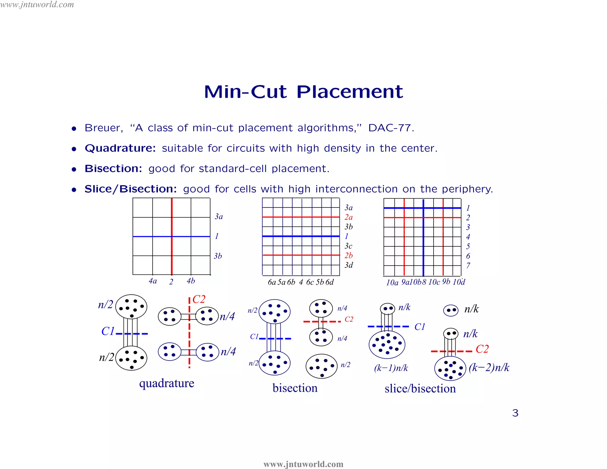
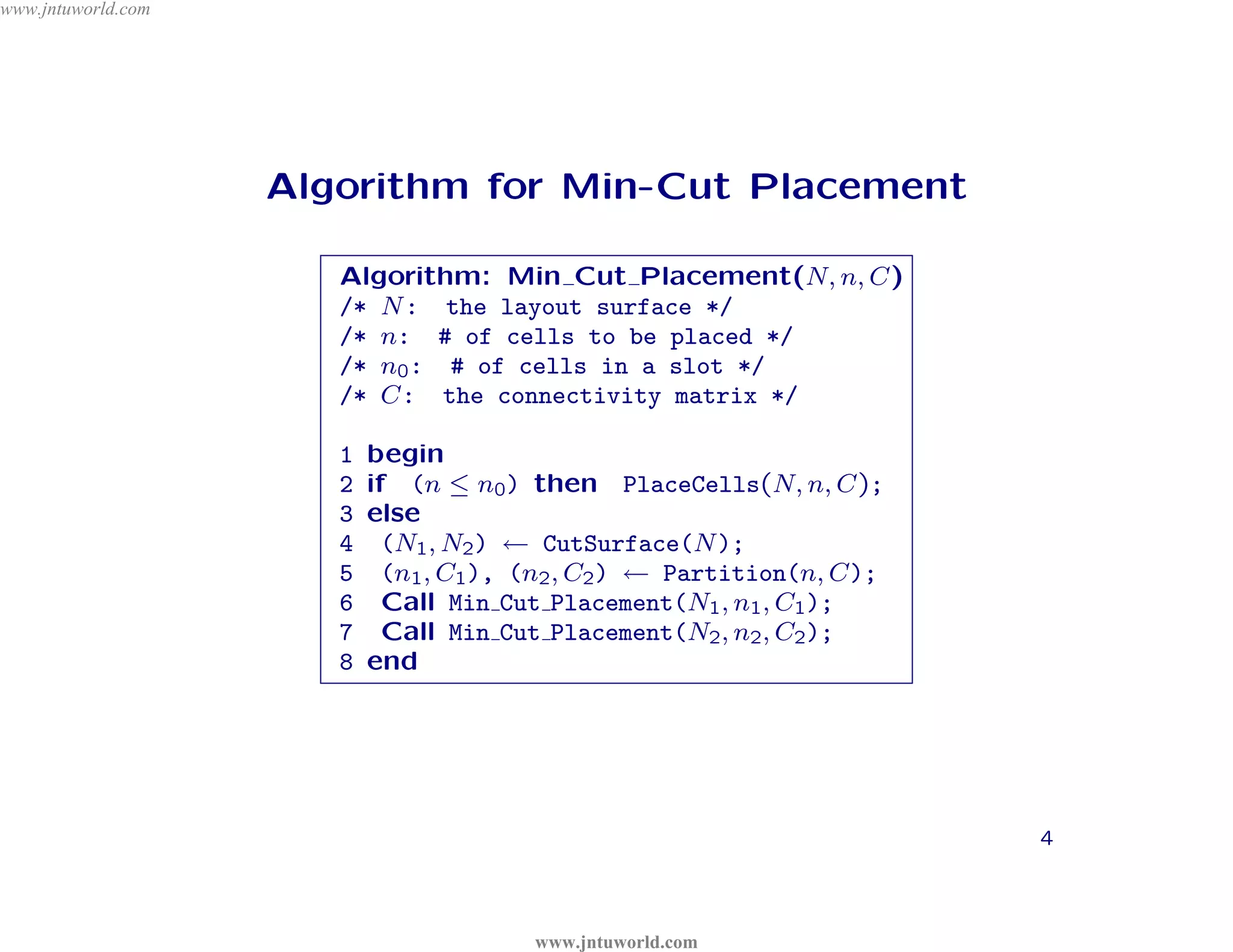
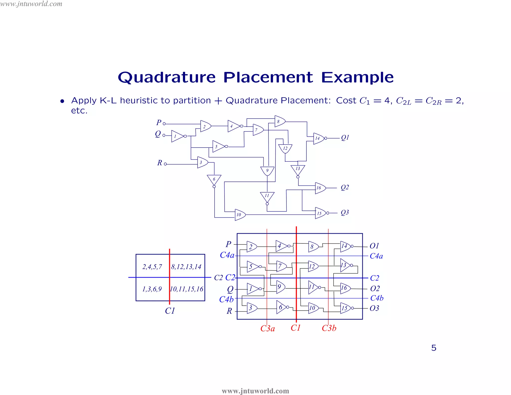
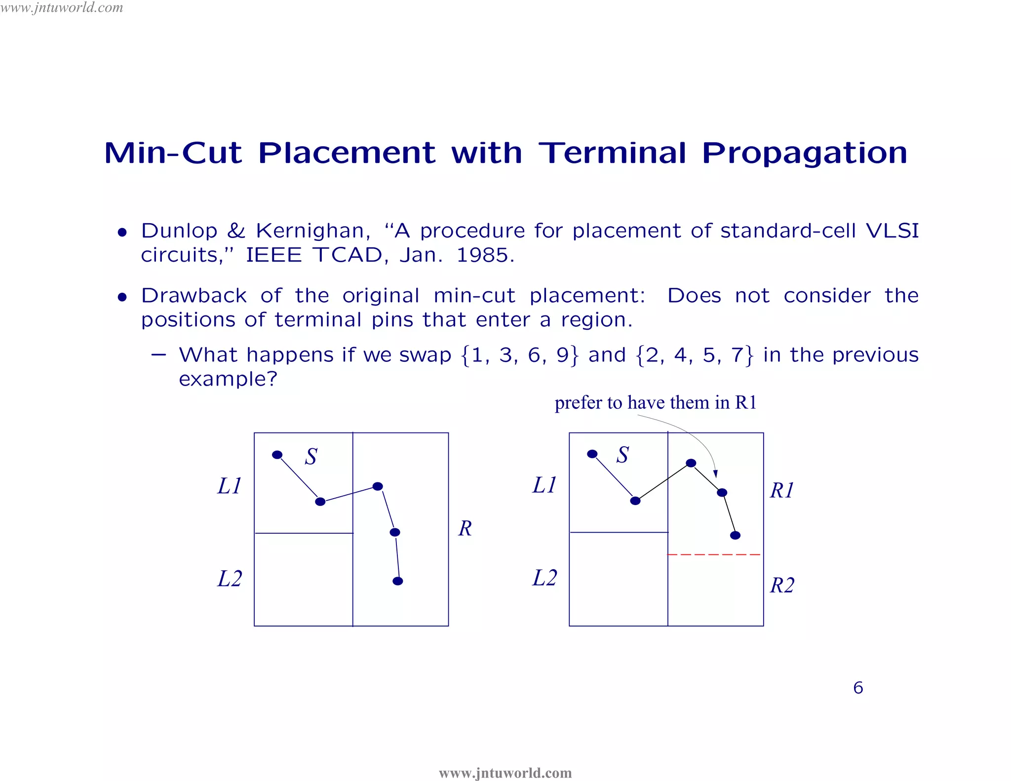
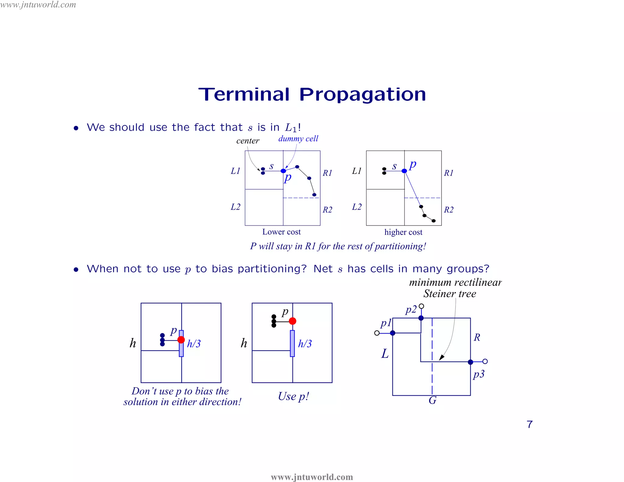
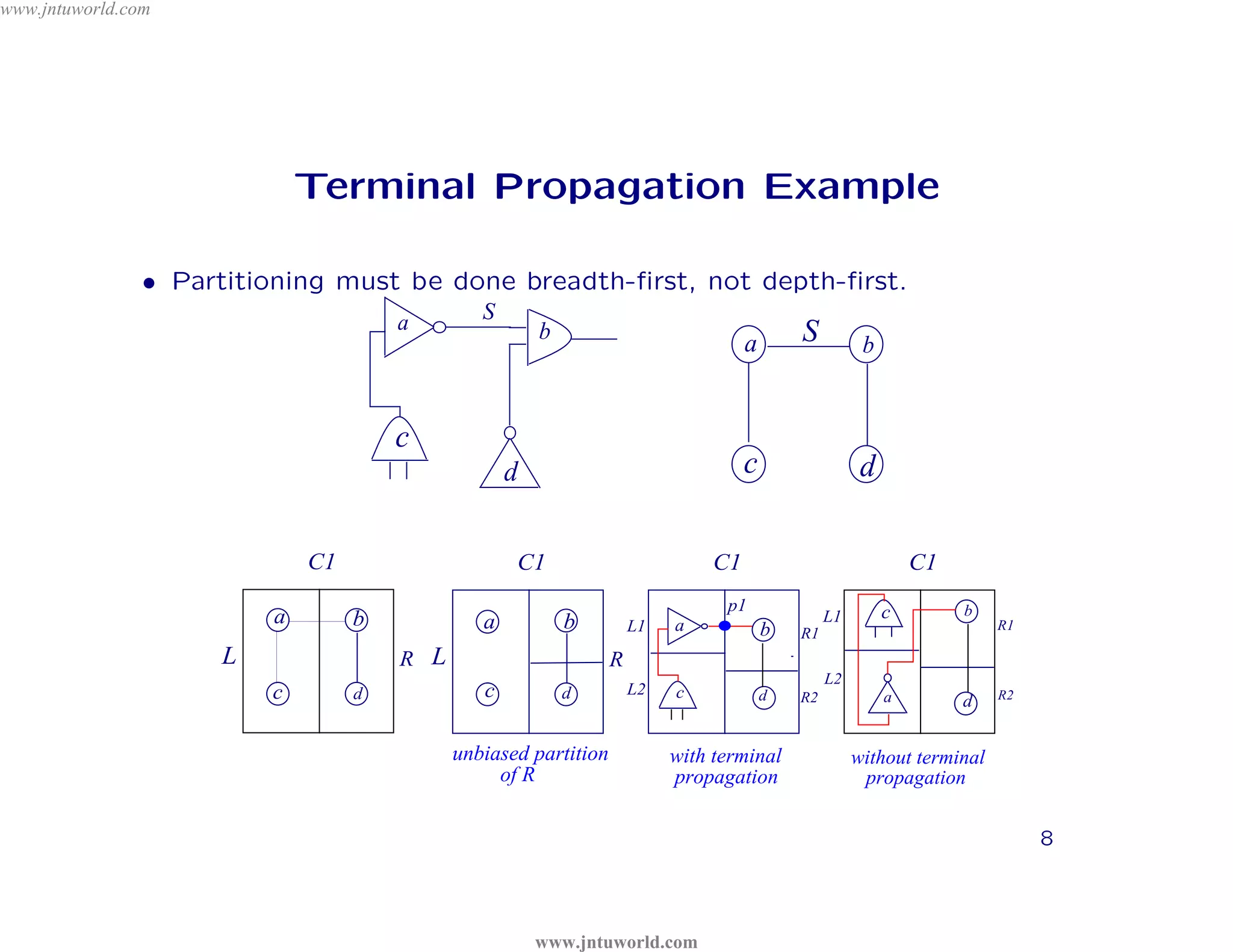
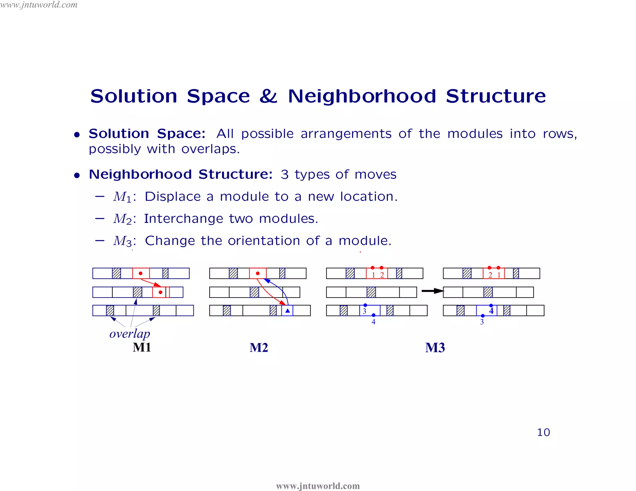
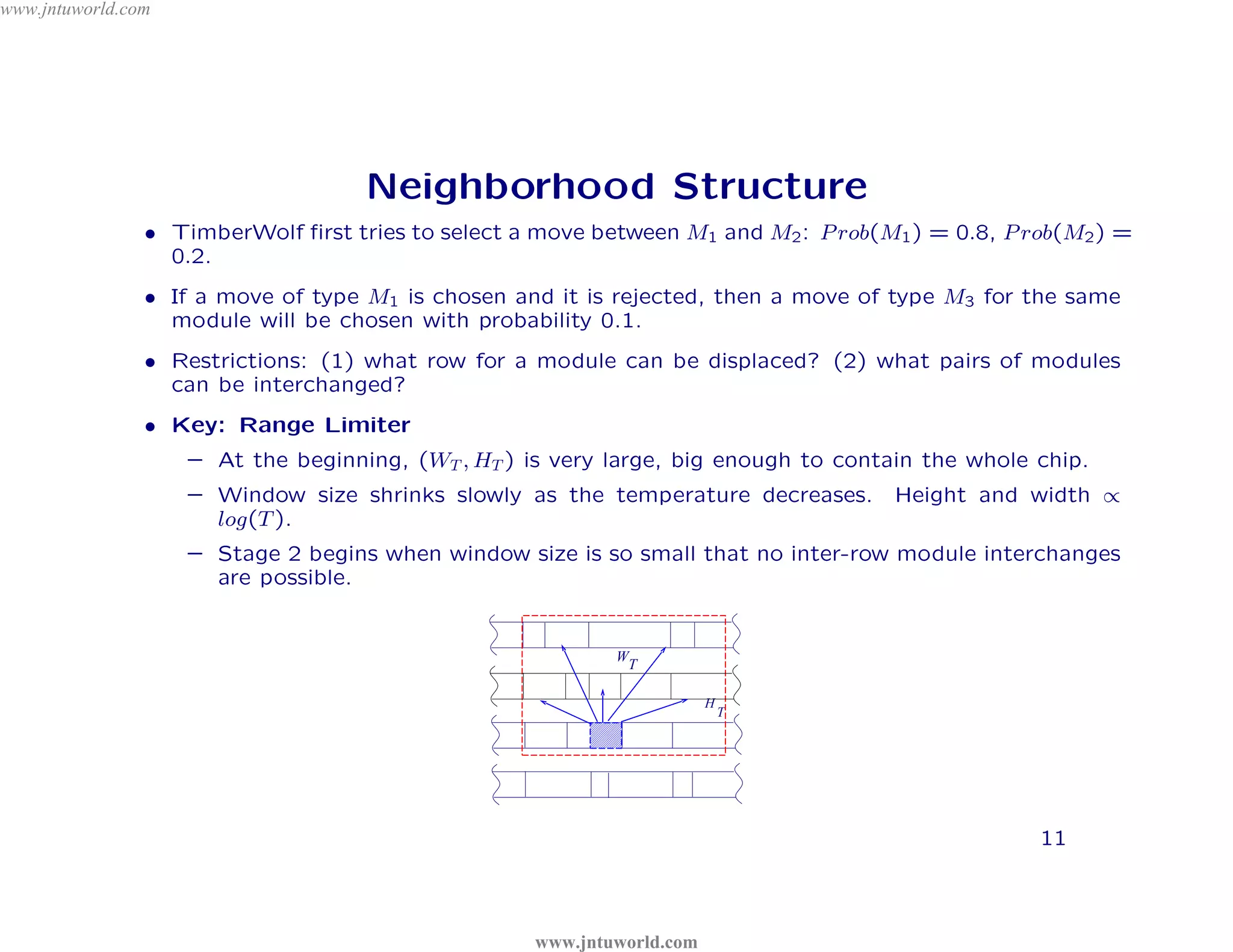
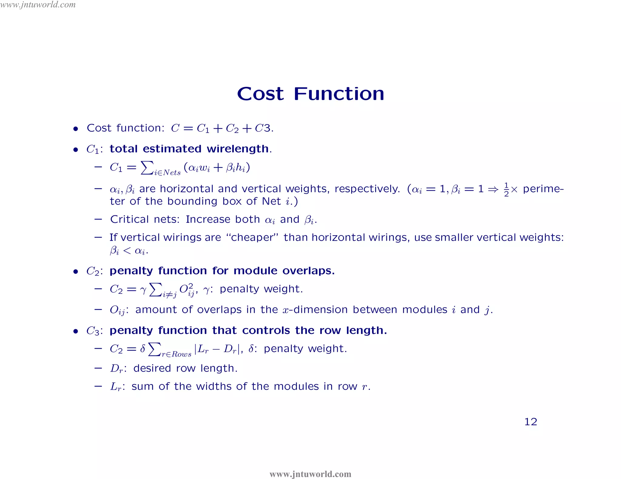
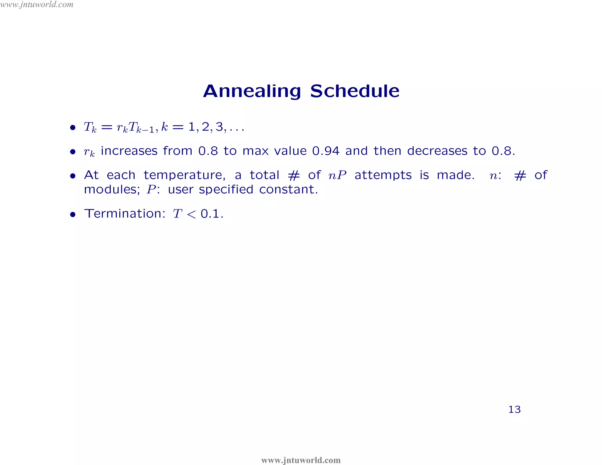

The document discusses placement algorithms used in circuit design. It describes the min-cut placement algorithm which partitions the layout surface and circuit into halves recursively to minimize wirelength. Terminal propagation is discussed to address limitations of min-cut by considering terminal pin positions. Placement by simulated annealing is also summarized, using neighborhood structures and cost functions to iteratively improve placement quality as temperature decreases.