The document is a preface and table of contents for a book about UMTS networks and radio access technology. It introduces the growth of mobile communications and the requirements for 3G systems, including new services and radio access aspects. It also briefly discusses enhancing technologies for 3G like smart antennas, multi-user detection, software defined radio, and integration challenges. The preface and contents set up the topics to be covered in the book at a high level.

![The UMTS Network and Radio Access Technology: Air Interface Techniques for Future Mobile Systems
Jonathan P. Castro
Copyright © 2001 John Wiley Sons Ltd
Print ISBN 0-471-81375-3 Online ISBN 0-470-84172-9
EVOLVING MOBILE NETWORKS
While the history of mobile communications is long [1–3], and the background of mo
bile networks therebyx is also long, in this chapter we focus on the historic evolution in
terms of network architecture and services starting with 2nd generation (2G) mobile
systems. In particular we consider the development of the architecture of Global Sys-
tems for Mobile Communications (GSM), since it is by far the most widespread mobile
system in the world today. This will provide the basis to cover the introduction of Uni-
versal Mobile Telecommunication Services (UMTS) in relation to its Core Network
(CN) and radio architectures. The latter will in turn serve as the platform to present
UMTS Radio Access Technology, which is one the aims of this book.
1.1 THE GROWTH OF MOBILE COMMUNICATIONS
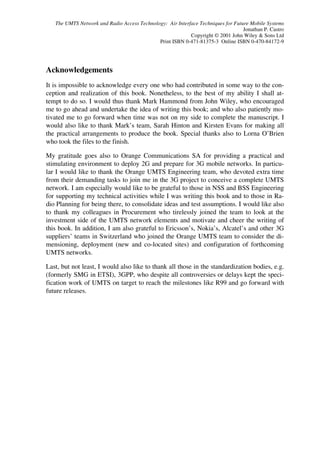
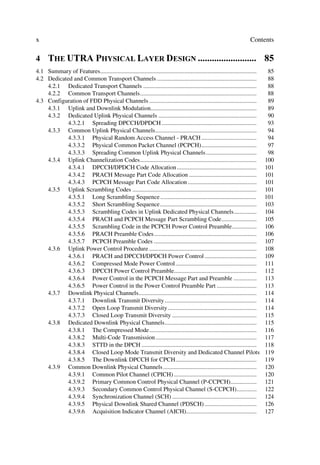
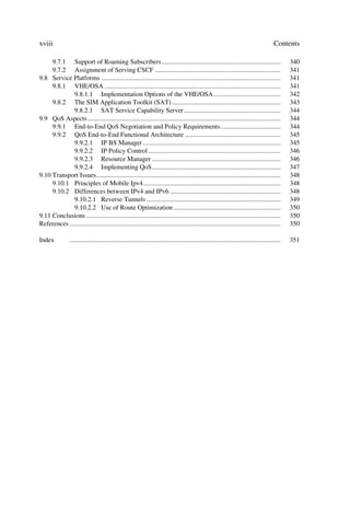
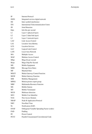
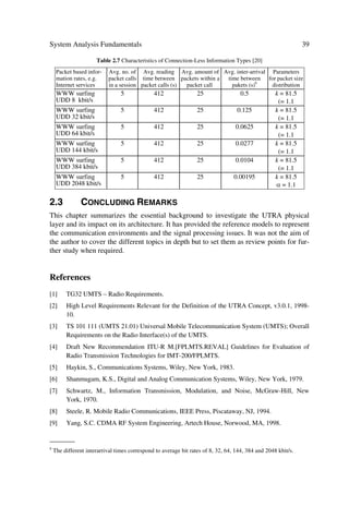
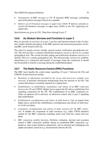
Today wireless voice service is one of the most convenient and flexible means of mod-
ern communications. GSM technology has been at the leading edge of this wireless
revolution. It is the technology of choice in over 120 countries and for more than 200
operators worldwide. Current estimates are that by the year 2001 there will be around
600 million wireless subscribers (e.g. mobile telephone users), out of which more than
50% will depend on GSM technology.
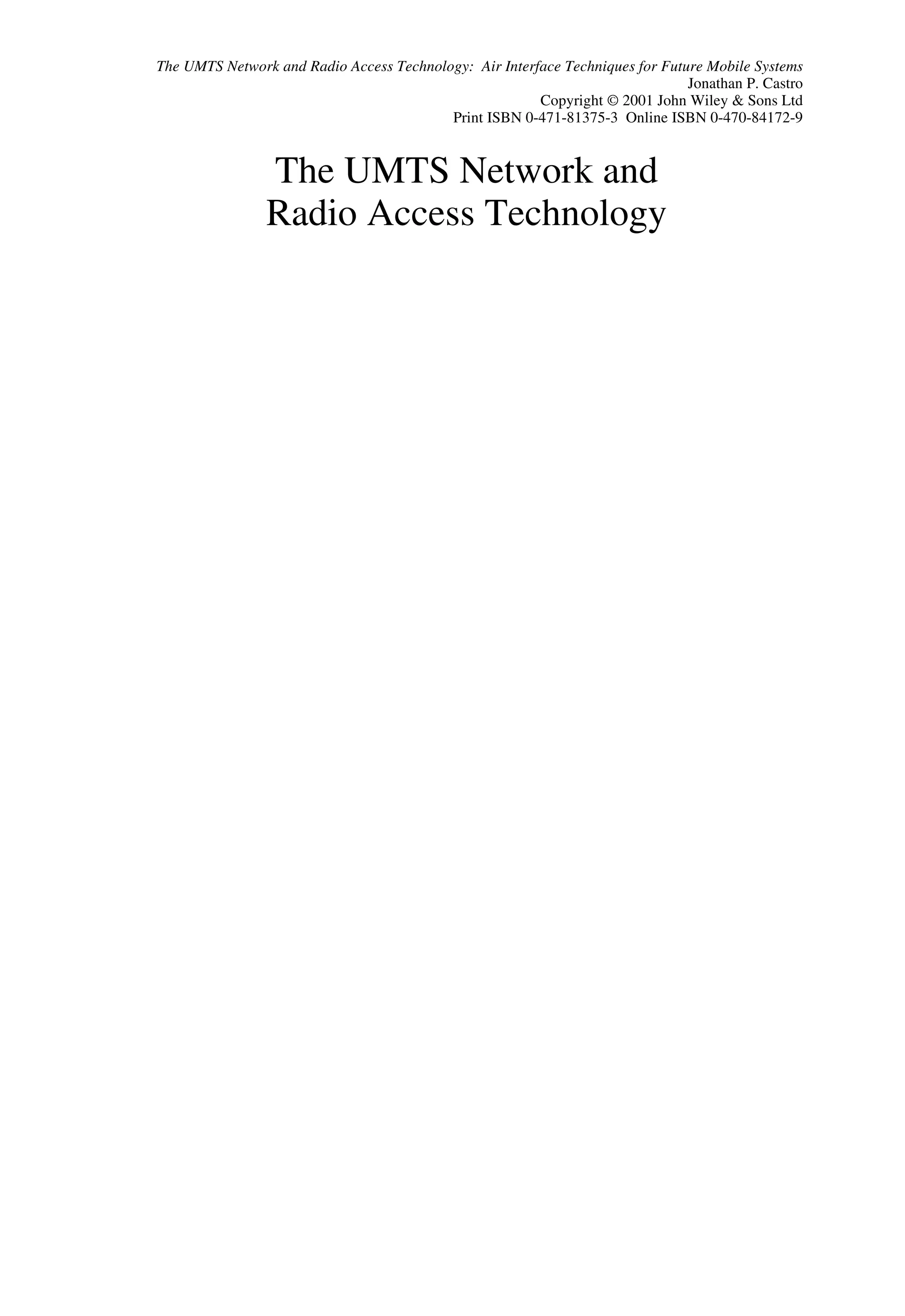
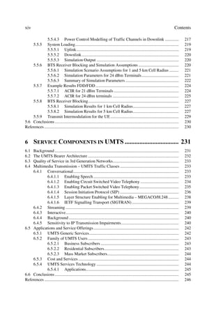
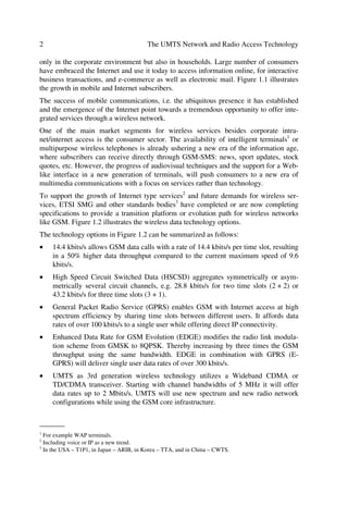
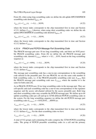
As the wireless revolution has been unfolding, the Internet has also shown a phenome-
nal growth simultaneously. The advent of the World Wide Web and web browsers has
propelled TCP/IP protocols into the main stream, and the Internet is widespread not
†
‚
v
y
y
v
€
Ã
0 RELOH
†
…
r
i ,QWHUQHW
v
…
p
†
i
ˆ
T
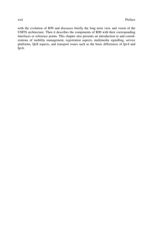
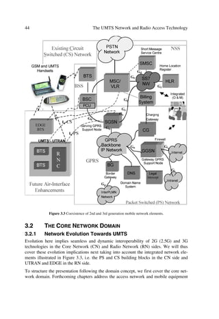
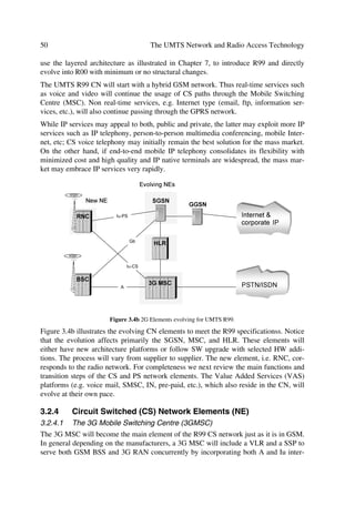
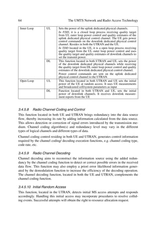
Figure 1.1 The growth of mobile and internet services.](https://image.slidesharecdn.com/wileytheumtsnetworkandradioaccesstechnologyairinterfacetechniquesforfuturemobile-12712253580361-phpapp02/85/Wiley-The-Umts-Network-And-Radio-Access-Technology-Air-Interface-Techniques-For-Future-Mobile-29-320.jpg)
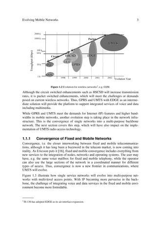
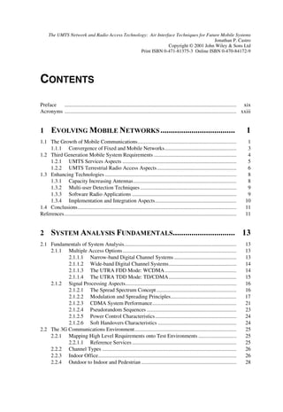
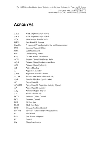
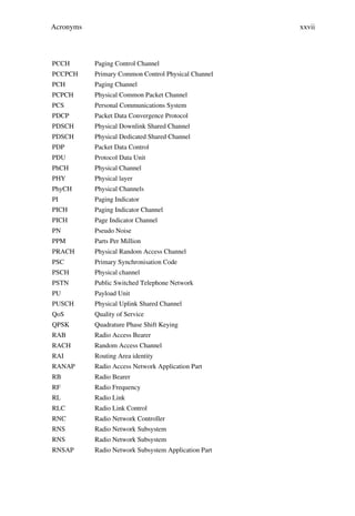
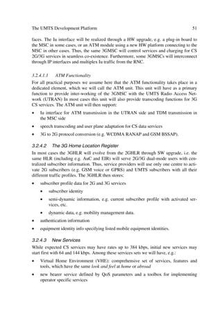
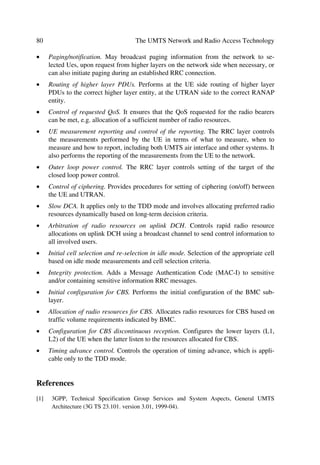
![%#ÃxÃ
LUFXLW +66' ('*(
ÃxÃ
*356
ÃxÃ
606
(('Ã (((Ã !Ã ! Ã !!Ã
@‰‚yˆ‡v‚Ã`rh…
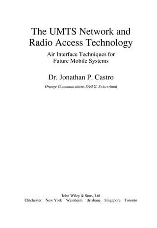
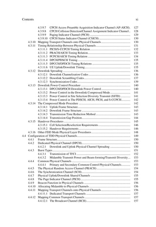
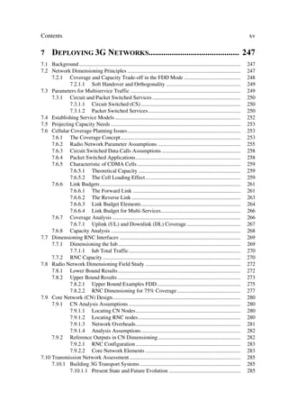
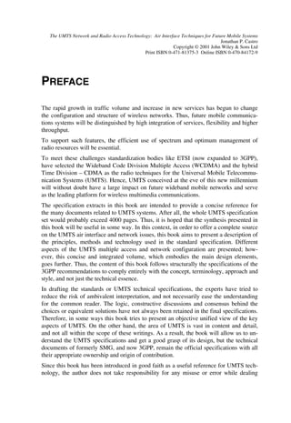
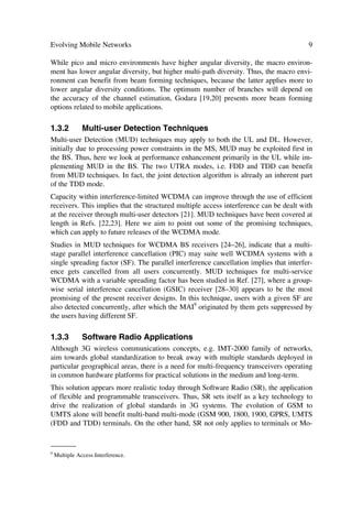
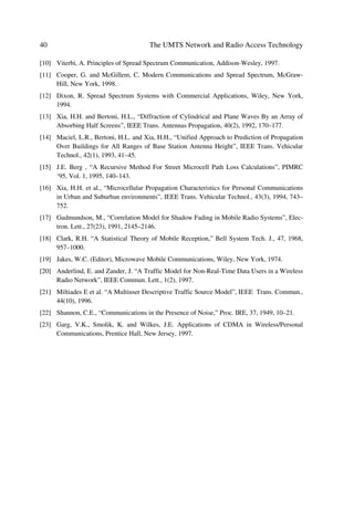
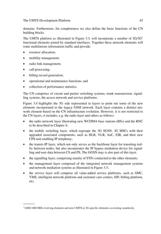
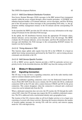
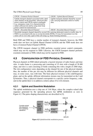
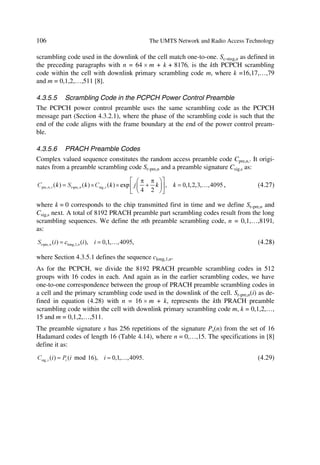
Figure 1.2 Evolution for wireless networks4, e.g. GSM.
Although the circuit switched enhancements such as HSCSD will increase transmission
rates, it is packet switched enhancements, which will meet the challenges or demands
posed on current wireless networks. Thus, GPRS and UMTS with EDGE as an interme-
diate solution will provide the platform to support integrated services of voice and data
including multimedia.
While GPRS and UMTS meet the demands for Internet (IP) features and higher band-
widths in mobile networks, another evolution step is taking place in the network infra-
structure. This is the convergence of single networks into a multi-purpose backbone
network. The next section covers this step, which will have also impact on the imple-
mentation of UMTS radio access technology.
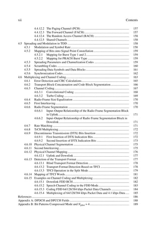
1.1.1 Convergence of Fixed and Mobile Networks
RQYHUJHQFH LH WKH FORVHU LQWHUZRUNLQJ EHWZHHQ IL[HG DQG PRELOH WHOHFRPPXQLFD
WLRQV DOWKRXJK LW KDV ORQJ EHHQ D EX]]ZRUG LQ WKH WHOHFRP PDUNHW LV QRZ FRPLQJ LQWR
UHDOLW $V (ULFVVRQ SXWV LW @ IL[HG DQG PRELOH FRQYHUJHQFH LQFOXGHV HYHUWKLQJ IURP
QHZ VHUYLFHV WR WKH LQWHJUDWLRQ RI QRGHV QHWZRUNV DQG RSHUDWLQJ VVWHPV 7KH XVHU PD
KDYH HJ WKH VDPH YRLFH PDLOER[ IRU IL[HG DQG PRELOH WHOHSKRQ ZKLOH WKH RSHUDWRU
FDQ DOVR XVH WKH ODUJH VHFWLRQV RI WKH QHWZRUN LQ D FRRUGLQDWHG PDQQHU IRU GLIIHUHQW
WSHV RI DFFHVV 7KXV FRQYHUJHQFH LV QRZ D QHZ IURQWLHU LQ FRPPXQLFDWLRQV ZKHUH
8076 ZLOO HYROYH
)LJXUH LOOXVWUDWH KRZ VLQJOH VHUYLFH QHWZRUNV ZLOO HYROYH LQWR PXOWLSXUSRVH QHW
ZRUNV ZLWK PXOWLOHYHO DFFHVV SRLQWV :LWK ,3 EHFRPLQJ PRUH SHUYDVLYH LQ WKH EDFN
ERQH WKH FKDOOHQJH RI LQWHJUDWLQJ YRLFH DQG GDWD VHUYLFHV LQ WKH IL[HG DQG PRELOH HQYL
URQPHQW EHFRPH PRUH IRUPLGDEOH
_______
4
IS-136 has adopted EDGE as its air-interface expansion.](https://image.slidesharecdn.com/wileytheumtsnetworkandradioaccesstechnologyairinterfacetechniquesforfuturemobile-12712253580361-phpapp02/85/Wiley-The-Umts-Network-And-Radio-Access-Technology-Air-Interface-Techniques-For-Future-Mobile-32-320.jpg)
![Evolving Mobile Networks 5
to the Core Network (CN). Hence, the 3G, or more specifically UMTS requirements in
this section cover three main areas, i.e. services, air-interface, and core network access.
1.2.1 UMTS Services Aspects
The scope of services can be largely focused on different issues like service manage-
ment, charging and billing, terminals, network management, quality of service, and se-
curity. Here, however, we will be looking at services from the principle side in other to
establish a framework to present the UMTS air-interface. An extract of the service prin-
ciples outlined in the ETSI specifications UMTS Services aspects – Service Principles
and UMTS Services [4] and Services capabilities [16], can be summarized as follows:
UMTS is the realization of a new generation of mobile communications technology for a
world in which personal communications services should allow person-to-person calling,
independent of location, the terminal used, the means of transmission (wired or wireless)
and the choice of technology.
UMTS shall therefore be in compliance with the following objectives:
(a) to provide a single integrated system in which the user can access services in an easy
to use and uniform way in all environments;
(b) to allow differentiation between service offerings of various serving networks and
home environments;
(c) to provide a wide range of telecommunications services including those provided by
fixed networks and requiring user bit rates of up to 2 Mbits/s as well as services spe-
cial to mobile communications. These services should be supported in residential,
public and office environments and in areas of diverse population densities. These
services are provided with a quality comparable with that provided by fixed net-
works such as ISDN;
(d) to provide services via hand held, portable, vehicular mounted, movable and fixed
terminals (including those which normally operate connected to fixed networks), in
all environments (in different service environments – residential, private domestic
and different radio environments) provided that the terminal has the necessary capa-
bilities;
(e) to provide support of roaming users by enabling users to access services provided by
their home environment in the same way even when roaming.
(f) to provide audio, data, video and particularly multimedia services;
(g) to provide for the flexible introduction of telecommunication services;
(h) to provide the capability to support Universal Personal Telecommunications (UPT);
(i) to provide within the residential environment the capability to enable a pedestrian
user to access all services normally provided by fixed networks;
(j) to provide within the office environment the capability to enable a pedestrian user to
access all services normally provided by PBXs and LANs;
(k) to provide a substitute for fixed networks in areas of diverse population densities, un-
der conditions approved by the appropriate national or regional regulatory authority.](https://image.slidesharecdn.com/wileytheumtsnetworkandradioaccesstechnologyairinterfacetechniquesforfuturemobile-12712253580361-phpapp02/85/Wiley-The-Umts-Network-And-Radio-Access-Technology-Air-Interface-Techniques-For-Future-Mobile-34-320.jpg)
![6 The UMTS Network and Radio Access Technology
(l) to provide support for interfaces which allow the use of terminals normally con-
nected to fixed networks.
In addition UMTS aims:
– to enable users to access a wide range of telecommunications services, including
many that are today undefined as well as multi-media and high data rates.
– to facilitate the provision of small, easy to use, low cost terminals with long talk
time and long standby operation;
– to provide an efficient means of using network resources (particularly radio spec-
trum).
Based on the above objectives, specific requirements related to services are outlined in
the ETSI Specifications [15–17]. These requirements are primarily concerned with
items such as Quality of Service, Security and Charging, Service Management, etc.
1.2.2 UMTS Terrestrial Radio Access Aspects
The UMTS Terrestrial Radio Access (UTRA) system requirements are based on the
service requirements. The latter sets the demands, which UTRA specification aims to
meet. Table 1.2 summarizes key (selected) requirements identified for the UTRA con-
cept from [18]:
Table 1.2 UTRA High Level Requirements
Key requirements Description
Bearer capabilities
Maximum user bit rates œ Rural Outdoor5: at least 144 kbit/s (goal to achieve 384 kbit/s),
maximum speed: 500 km/h
œ Suburban Outdoor6: at least 384 kbps (goal to achieve 512
kbit/s), maximum speed: 120 km/h
œ Indoor/Low range outdoor7: at least 2 Mbps, maximum speed: 10
km/h
œ The UTRA definition should allow evolution towards higher bit
rates
Flexibility œ Negotiation of bearer service attributes (bearer type, bit rate, de-
lay, BER, etc.)
œ Parallel bearer services (service mix), real-/non-real-time
communication modes, etc.
œ Circuit and packet oriented bearers
œ Supports scheduling (and pre-emption) of bearers (including
control bearers) within priority
œ Adaptability of link to quality, traffic and network load, as well
as radio conditions.
œ Wide range of bit rates should be supported with sufficient granu-
larity
_______
5
The specified bit rate will be available throughout the operator’s service area, with the possibility of large cells.
6
The specified bit rate will be available with complete coverage of a suburban or urban area, using microcells or smaller
macrocells.
7
The specified bit rate will be available indoors and localised coverage outdoors.](https://image.slidesharecdn.com/wileytheumtsnetworkandradioaccesstechnologyairinterfacetechniquesforfuturemobile-12712253580361-phpapp02/85/Wiley-The-Umts-Network-And-Radio-Access-Technology-Air-Interface-Techniques-For-Future-Mobile-35-320.jpg)
![Evolving Mobile Networks 9
While pico and micro environments have higher angular diversity, the macro environ-
ment has lower angular diversity, but higher multi-path diversity. Thus, the macro envi-
ronment can benefit from beam forming techniques, because the latter applies more to
lower angular diversity conditions. The optimum number of branches will depend on
the accuracy of the channel estimation, Godara [19,20] presents more beam forming
options related to mobile applications.
1.3.2 Multi-user Detection Techniques
Multi-user Detection (MUD) techniques may apply to both the UL and DL. However,
initially due to processing power constraints in the MS, MUD may be exploited first in
the BS. Thus, here we look at performance enhancement primarily in the UL while im-
plementing MUD in the BS. The two UTRA modes, i.e. FDD and TDD can benefit
from MUD techniques. In fact, the joint detection algorithm is already an inherent part
of the TDD mode.
Capacity within interference-limited WCDMA can improve through the use of efficient
receivers. This implies that the structured multiple access interference can be dealt with
at the receiver through multi-user detectors [21]. MUD techniques have been covered at
length in Refs. [22,23]. Here we aim to point out some of the promising techniques,
which can apply to future releases of the WCDMA mode.
Studies in MUD techniques for WCDMA BS receivers [24–26], indicate that a multi-
stage parallel interference cancellation (PIC) may suite well WCDMA systems with a
single spreading factor (SF). The parallel interference cancellation implies that interfer-
ence gets cancelled from all users concurrently. MUD techniques for multi-service
WCDMA with a variable spreading factor has been studied in Ref. [27], where a group-
wise serial interference cancellation (GSIC) receiver [28–30] appears to be the most
promising of the present receiver designs. In this technique, users with a given SF are
also detected concurrently, after which the MAI9 originated by them gets suppressed by
the users having different SF.
1.3.3 Software Radio Applications
Although 3G wireless communications concepts, e.g. IMT-2000 family of networks,
aim towards global standardization to break away with multiple standards deployed in
particular geographical areas, there is a need for multi-frequency transceivers operating
in common hardware platforms for practical solutions in the medium and long-term.
This solution appears more realistic today through Software Radio (SR), the application
of flexible and programmable transceivers. Thus, SR sets itself as a key technology to
drive the realization of global standards in 3G systems. The evolution of GSM to
UMTS alone will benefit multi-band multi-mode (GSM 900, 1800, 1900, GPRS, UMTS
(FDD and TDD) terminals. On the other hand, SR not only applies to terminals or Mo-
_______
9
Multiple Access Interference.](https://image.slidesharecdn.com/wileytheumtsnetworkandradioaccesstechnologyairinterfacetechniquesforfuturemobile-12712253580361-phpapp02/85/Wiley-The-Umts-Network-And-Radio-Access-Technology-Air-Interface-Techniques-For-Future-Mobile-38-320.jpg)
![10 The UMTS Network and Radio Access Technology
bile Stations (MS) but also the to the Base Stations (BS). In the sequel we cover SR as
part of the enabling techniques in the MS and BS.
The main limitation of the feasibility of MUD in real commercial systems has been the
disproportionate processing speeds afforded by current DSP10 technology and the re-
quirement of the detection and estimation algorithms. Although overall performance of
DSPs has increased and keeps increasing, 3G systems also are pushing the signal proc-
essing capabilities higher and higher. Tasks such as high-data-rate signal acquisition,
more accurate channel estimation for highly selective fading environments, fast signal
quality estimation algorithms involved in power control, and optimum combining of
signals for diversity gains in space and time, demand all the power a processor can pro-
duce. These demands can be realized more rapidly through Software Defined Radio
(SDR).
Thus, while compatibility between standards remains attractive, SDRs will shape into
software and hardware reconfigurable radios in the RF, intermediate frequency (IF), as
well as base-band processing stages [31–34].
1.3.4 Implementation and Integration Aspects
Research studies aiming to improve the overall performance of multiple access tech-
niques such as WCDMA or TDCDMA have provided interesting and applicable meth-
ods. However, these results may not necessarily be part of the first UTRA commercial
systems in the next 2 years. Thus, it will be some time before techniques such as Soft-
ware Radio, Adaptive Antennas, and Multi-user Detection enhance capacity, coverage
and increase system stability.
Implementation and integration appear as key limitations to bring these advanced tech-
niques into operating systems or near future11 exploitable networks. Processing power
demands for example, do not allow rapid implementation of the above methods. Fur-
thermore, integrating such techniques into smaller components is a great challenge. This
means, that while less optimum supporting techniques like system on a chip, maximiz-
ing power consumption, or operating at very low power come into place; the aforemen-
tioned improvements will remain academic.
At present, while UMTS frequency licensing becomes big business for governments,
operators seem to have fall into the spin of supremacy and consolidation for market
share and have somehow forgotten the timeliness of technology. Manufacturers are
finding themselves in a race to supply plain vanilla solutions and are incapable of im-
plementing true breakthroughs in multiple access or radio-access techniques.
Thus, it seems reasonable to think that it may be to the benefit of industry as a whole
and governments themselves to concentrate on putting more resources into the realiza-
tion of new communications technologies than just coping with spectrum allocation and
acquisition to offer services with higher transmission rates. Such an approach will make
_______
10
Digital Signal Processor.
11
Recent evaluation on end-to-end industrial solutions do not yet show these techniques as part of a product.](https://image.slidesharecdn.com/wileytheumtsnetworkandradioaccesstechnologyairinterfacetechniquesforfuturemobile-12712253580361-phpapp02/85/Wiley-The-Umts-Network-And-Radio-Access-Technology-Air-Interface-Techniques-For-Future-Mobile-39-320.jpg)
![Evolving Mobile Networks 11
UMTS a clear platform for advanced technology from the start and not just one more
alternative to provide new mobile applications.
1.4 CONCLUSIONS
Chapter 1 has presented a window to perceive the environment into which UMTS12 will
develop. It has set the background to introduce UMTS Radio Access Technology, the
aim of this book. From the impressive growth of GSM and the Internet, as well as the
UMTS air-interface specification requirements, UMTS Terrestrial Radio Access
(UTRA) is well positioned to play the key role in the convergence of telecommunica-
tions towards integrated services. Therefore, the contents of future chapters describe in
more detail some of key elements shown generically in this chapter.
References
[1] Mehrotra, A. “Cellular Radio – Analog and Digital Systems”, Ch1 Artech House, Nor-
wood, MA, 1994.
[2] Young, W.R. “Advanced Mobile Phone Service: Introduction, Background, and Objec-
tives”, Bell System Tech. J., 58(1), 1979, 1–14.
[3] Macdonald, V.H. “Advanced Mobile Phone Service: The Cellular Concept”, Bell System
Tech. J., 58(1), 1979, 15–41.
[4] UMTS 22.01 Service Aspects – Service Principles.
[5] UMTS 22.25 Quality of Service and Network Performance.
[6] UMTS 22.05 Service Capabilities.
[7] UMTS 33.20 Security Principles for UMTS.
[8] UMTS 22.15 Security and Charging.
[9] UMTS 22.24 New charging and Accounting Mechanisms.
[10] UMTS 22.70 Virtual Home Environment.
[11] UMTS 22.71 Automatic Establishment of Roaming Agreements.
[12] UMTS 23.05 Network Principles.
[13] TG24 Requirements for Charging, Billing, Accounting, Tariffing.
[14] UMTS 22.20 Service Management.
[15] UMTS 22.25 Quality of Service and Network Performance.
[16] Ericsson, Connection No. 2 June 1999.
[17] TG32 UMTS - Radio Requirements.
_______
12
In particular UTRA.](https://image.slidesharecdn.com/wileytheumtsnetworkandradioaccesstechnologyairinterfacetechniquesforfuturemobile-12712253580361-phpapp02/85/Wiley-The-Umts-Network-And-Radio-Access-Technology-Air-Interface-Techniques-For-Future-Mobile-40-320.jpg)
![12 The UMTS Network and Radio Access Technology
[18] High Level Requirements Relevant for the Definition of the UTRA concept, v3.0.1, 1998-
10.
[19] Godara, L.C. “Application of Antenna Arrays to Mobile Communications”, Part I: Per-
formance Improvement, Feasibility, And System Considerations”, Proc. IEEE, 85(7), 1997,
1031–1060.
[20] Godara, L.C. “Application of Antenna Arrays to Mobile Communications, Part II: Beam-
forming And Direction-of-Arrival Considerations”, Proc. IEEE, 85(8), 1997, 1195–1245.
[21] Verdú, S. “Minimum probability of error for asynchronous Gaussian multiple-access chan-
nels”, IEEE Trans. Inform. Theory, 32(1), 1986, 85–96.
[22] Verdú, S. Multiuser Detection, Cambridge University Press, Cambridge, UK, 1998.
[23] Juntti, M. and Glisic, S. “Advanced CDMA For Wireless Communications”, in Wireless
Communications: TDMA Versus CDMA (eds. S. G. Glisic and P. A. Leppänen), Kluwer,
Dordrecht, Chapter 4, 1997, 447–490.
[24] Ojanperä, T., Prasad, R. and Harada, H. Qualitative Comparison of Some Multiuser De-
tector Algorithms for Wideband CDMA, Proc. IEEE Vehic. Tech. Conf., 1, 1998, 46–50.
[25] Correal, N.S., Swanchara, S.F. and Woerner, B.D. “Implementation Issues For Multiuser
DS-CDMA Receivers, Int. J. Wireless Inform. Networks, 5(3), 1998, 257–279.
[26] Juntti, M. and Latva-aho, M. “Multiuser Receivers For CDMA Systems in Rayleigh Fading
Channels”, IEEE Trans. Vehic. Tech., 2000, in press.
[27] Wijting, C.S., Ojanperä, T., Juntti, M.J., Kansanen, K. and Prasad, R. Groupwise Serial
Multiuser Detectors for Multirate DS-CDMA, Proc. IEEE Vehic. Tech. Conf., 1999, in
press.
[28] Juntti, M. “Performance of Multiuser Detection in Multirate CDMA Systems”, Wireless
Pers. Commun., 11(3), 1999, 293–311.
[29] Juntti, M. “Performance of Multiuser Detection in Multirate CDMA Systems”, Wireless
Pers. Commun., 11(3), 1999, 293–311.
[30] Juntti, M. “Multiuser Detector Performance Comparisons in Multirate CDMA Systems”,
Proc. VTC’98, Ottawa, Canada, 1998, 36–40.
[31] Seskar, I. and Mandayam, N., “Software-Defined Radio Architectures for Interference
Cancellation in DS-CDMA Systems”, IEEE Pers. Commun., 6(4), 1999, 26–34.
[32] Tsurumi, H. and Suzuki, Y. “Broadband RF Stage Architecture for Software Defined Radio
in Handheld Terminal Applications”, IEEE Commun. Mag., 37(2), 1999, 90–95.
[33] Walden, R.H. “Performance Trends of Analog-to-Digital Converters”, IEEE Commun.
Mag., 37(2), 1999, 96–101.
[34] Chester, D.B. “Digital IF Filter Technology for 3G Systems: An Introduction”, IEEE
Commun. Mag., 37(2), 1999, 102–107.](https://image.slidesharecdn.com/wileytheumtsnetworkandradioaccesstechnologyairinterfacetechniquesforfuturemobile-12712253580361-phpapp02/85/Wiley-The-Umts-Network-And-Radio-Access-Technology-Air-Interface-Techniques-For-Future-Mobile-41-320.jpg)
![The UMTS Network and Radio Access Technology: Air Interface Techniques for Future Mobile Systems
Jonathan P. Castro
Copyright © 2001 John Wiley Sons Ltd
Print ISBN 0-471-81375-3 Online ISBN 0-470-84172-9
SYSTEM ANALYSIS FUNDAMENTALS
2.1 FUNDAMENTALS OF SYSTEM ANALYSIS
Third generation systems focus on providing a universal platform to afford multifarious
communications options at all levels, i.e. the radio as well as the core network sides.
This implies the application of optimum techniques in multiple access and inter-
working protocols for the physical and upper layers, respectively. This chapter dis-
cusses the background of the multiple access or radio part of the UMTS specification.
Several sources [5–9] have already covered all types of fundamentals related to the air-
interface. Thus, we focus only on the communications environment to access the radio
link performance for coverage analysis and network dimensioning in forthcoming chap-
ters.
2.1.1 Multiple Access Options
The access technologies utilized in UTRA are unique because of the type of implemen-
tation and not because they are new. The combination of CDMA and TDMA techniques
in one fully compatible platform, make UTRA special. The WCDMA and hybrid
TDMA/CDMA form the FDD and TDD modes to co-exist seamlessly to meet the
UMTS services and performance requirements. In the sequel we cover the fundamental
characteristics for each access technique which serves as a building block for the UTRA
modes.
2.1.1.1 Narrow-band Digital Channel Systems
The two basic narrow-band techniques include FDMA (using frequencies) and TDMA
(using time slots). In the first case, frequencies are assigned to users while guard bands
maintain between adjacent signal spectra to minimize interference between channels. In
the second case, data from each user takes place in time intervals called slots. The ad-
vantages of FDMA lie on efficient use of codes and simple technology requirements.
But the drawbacks of operating at a reduced signal/interference ratio and the inhibiting
flexibility1 of bit rate capabilities outweigh the benefits. TDMA allows flexible rates in
multiples of basic single channels and sub-multiples for low-bit rate broadcast transmis-
sion. It offers frame-by-frame signal management with efficient guard band arrange-
ments to control signal events. However, it requires substantial amounts of signal proc-
essing resources to cope with matched filtering and synchronization needs.
_______
1 The maximum bit per channel remains fixed and low.](https://image.slidesharecdn.com/wileytheumtsnetworkandradioaccesstechnologyairinterfacetechniquesforfuturemobile-12712253580361-phpapp02/85/Wiley-The-Umts-Network-And-Radio-Access-Technology-Air-Interface-Techniques-For-Future-Mobile-42-320.jpg)
![14 The UMTS Network and Radio Access Technology
2.1.1.2 Wide-band Digital Channel Systems
Some of the drawbacks and limitations in the narrow-band channel systems made room
for wide-band channel system designs. In wide-band systems the entire bandwidth re-
mains available to each user, even if it is many times larger than the bandwidth required
to convey the information. These systems include primarily Spread Spectrum (SS) sys-
tems, e.g. Direct Sequence Spread Spectrum (DSSS) and Frequency Hopping Spread
Spectrum (FHSS). In DSSS, emphasized in this book, the transmission bandwidth ex-
ceeds the coherent bandwidth, i.e. the received signal after de-spreading resolves into
multiple time-varying delay signals that a RAKE receiver can exploit to provide an in-
herent time diversity receiver in a fading environment. In addition, DSSS has greater
resistance to interference effects when compared to FDMA and TDMA. The latter
greatly simplifies frequency band assignment and adjacent cell interference. In addition,
capacity improvements with DSSS or more commonly referred to as DS-CDMA2, re-
sulting from the voice activity factor, which we cannot apply effectively to FDMA or
TDMA. With DS-CDMA, e.g. adjacent micro-cells share the same frequencies, whereas
interference in FDMA and TDMA does not allow this. Other benefits and features can
be found in [10–12]. Here we focus on the WCDMA or FDD mode and TDMA/
CDMA or TDD mode of the UTRA solution.
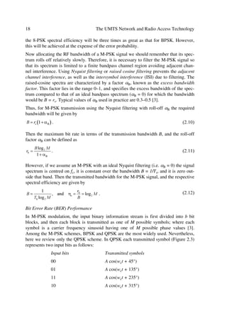
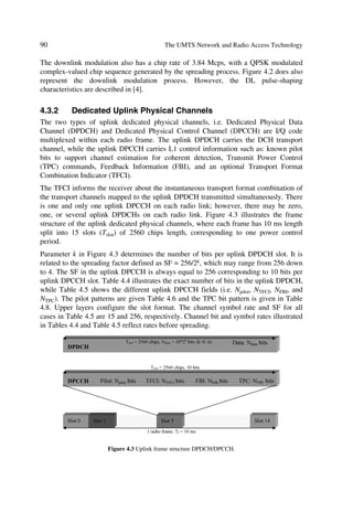
2.1.1.3 The UTRA FDD Mode: WCDMA
Figure 2.1 illustrates some of the UTRA Frequency Division Duplexing (FDD) charac-
teristics. This mode uses Wide-band Direct-Sequence Code Division Multiple Access
(DS-CDMA), denoted WCDMA. To support bit rates up to 2 Mbps, it utilizes a variable
spreading factor and multi-code links. It supports highly variable user data rates through
the allocation of 10 ms frames, during which the user data rate remains constant, al-
though the latter may change from frame to frame depending on the network control. It
realizes a chip rate of 3.84 Mcps within 5 MHz carrier bandwidth, although the actual
carrier spacing can be selected on a 200 kHz grid between approximately 4.4 and
5 MHz, depending on the interference situation between the carriers.
ÃA…r„ˆrp’Ã
Ã
Wh…vhiyrÃiv‡Ã…h‡rÃ
†r…‰vpr†Ã
Q‚r…Ã
CvtuÃiv‡Ã…h‡rÃ
##$ÃHC“Ã
†r…‰vpr†Ã
Uv€rÃ
9vssr…r‡Ã†ƒ…rhqvtÃshp‡‚…†Ã
À†Ã
rtÃhyy‚vtÃ'±'#Ãxƒi†Ã
Figure 2.1 The UTRA WCDMA or FDD mode characteristics.
_______
2 Direct Sequence Code Division Multiple Access.](https://image.slidesharecdn.com/wileytheumtsnetworkandradioaccesstechnologyairinterfacetechniquesforfuturemobile-12712253580361-phpapp02/85/Wiley-The-Umts-Network-And-Radio-Access-Technology-Air-Interface-Techniques-For-Future-Mobile-43-320.jpg)
![16 The UMTS Network and Radio Access Technology
2.1.2 Signal Processing Aspects
In the following, we review Signal Processing characteristics for the WCDMA as well
as TD/CDMA as a base to describe key functions of the UTRA FDD and TDD modes.
These include spreading aspects and modulation and coding.
2.1.2.1 The Spread Spectrum Concept
Digital designs of communications systems aim to maximise capacity utilization. We
can for example increase channel capacity by increasing channel bandwidth, and/or
transmitted power. In this context, CDMA operates at much lower S/N ratios as a result
of the extra channel bandwidth used to achieve good performance at low signal-to-noise
ratio. From Shannon’s channel capacity principle [22] expressed as:
6Þ
= % ORJ Î +
Ï](https://image.slidesharecdn.com/wileytheumtsnetworkandradioaccesstechnologyairinterfacetechniquesforfuturemobile-12712253580361-phpapp02/85/Wiley-The-Umts-Network-And-Radio-Access-Technology-Air-Interface-Techniques-For-Future-Mobile-45-320.jpg)
![5
From Ref. [23] in a spread-spectrum system, thermal noise and interference determine
the noise level. Hence, for a given user, the interference is processed as noise. Then, the
input and output S/N ratios can relate as:
Ë6Û Ë6Û
Ì Ü = *S Ì Ü](https://image.slidesharecdn.com/wileytheumtsnetworkandradioaccesstechnologyairinterfacetechniquesforfuturemobile-12712253580361-phpapp02/85/Wiley-The-Umts-Network-And-Radio-Access-Technology-Air-Interface-Techniques-For-Future-Mobile-48-320.jpg)
![1R Í 1 ÝL Í 1 Ý R
2.1.2.2 Modulation and Spreading Principles
In wide-band spread-spectrum systems like the FDD mode, the entire bandwidth of the
system remains available to each user. To such systems, the following principles apply:
first, the spreading signal has a bandwidth much larger than the minimum bandwidth
required to transfer desired information or base-band data. Second, data spreading oc-
curs by means of a code spreading signal, where the code signal is independent of the
data and is of a much higher rate than the data signal. Lastly, at the receiver, de-
spreading takes place by the cross-correlation of the received spread signal with a syn-
chronized replica of the same signal used to spread the data [23].
2.1.2.2.1 Modulation
If we view Quadrature Phase-Shift Keying (QPSK) as two independent Binary Phase-
Shift Keying (BPSK) modulations, then we can assume the net data rate doubles. We
now provide the background for QPSK to serve as background to the applications in
UTRA presented in Chapter 4.
For all practical purposes we start with M-PSK, where M = 2b, and b = 1, 2 or 3 (i.e. 2-
PSK or BPSK, 4-PSK or QPSK and 8-PSK). In the case of QPSK modulation the phase
of the carrier can take on one of four values 45°, 135°, 225°, or 315° as we shall see
later. The QPSK power spectral density (V2/Hz) could be then defined as
Ñ VLQ Î p7V ( I - I F ) Þ á
Ô àÔ
6 I](https://image.slidesharecdn.com/wileytheumtsnetworkandradioaccesstechnologyairinterfacetechniquesforfuturemobile-12712253580361-phpapp02/85/Wiley-The-Umts-Network-And-Radio-Access-Technology-Air-Interface-Techniques-For-Future-Mobile-52-320.jpg)
![The power spectral density of an unfiltered M-PSK signal occupies a bandwidth which
is a function of the symbol rate rs = (1/Ts). Thus, for a given transmitter symbol, the
power spectrum for any M-PSK signal remains the same regardless of the number M of
symbol levels used. This implies that BPSK, QPSK and 8-PSK signals each have the
same spectral shape if Ts remains the same in each case.
Spectral Efficiency
For a M-ary PSK scheme each transmitted symbol represents log2M bits. Hence, at a
fixed input bit rate, as the value of M increases, the transmitter symbol rate decreases;
which means that there is in increase in spectral efficiency for larger M.
Thus, if for any digital modulation the spectral efficiency hs, (i.e. the ratio of the input
data rate rb and the allocated channel bandwidth B) is given by:
UE
hV = ELWV +]](https://image.slidesharecdn.com/wileytheumtsnetworkandradioaccesstechnologyairinterfacetechniquesforfuturemobile-12712253580361-phpapp02/85/Wiley-The-Umts-Network-And-Radio-Access-Technology-Air-Interface-Techniques-For-Future-Mobile-55-320.jpg)
![18 The UMTS Network and Radio Access Technology
the 8-PSK spectral efficiency will be three times as great as that for BPSK. However,
this will be achieved at the expense of the error probability.
Now allocating the RF bandwidth of a M-PSK signal we should remember that its spec-
trum rolls off relatively slowly. Therefore, it is necessary to filter the M-PSK signal so
that its spectrum is limited to a finite bandpass channel region avoiding adjacent chan-
nel interference. Using Nyquist filtering or raised cosine filtering prevents the adjacent
channel interference, as well as the intersymbol interference (ISI) due to filtering. The
raised-cosine spectra are characterized by a factor aB, known as the excess bandwidth
factor. This factor lies in the range 0–1, and specifies the excess bandwidth of the spec-
trum compared to that of an ideal bandpass spectrum (aB = 0) for which the bandwidth
would be B = rs. Typical values of aB used in practice are 0.3–0.5 [3].
Thus, for M-PSK transmission using the Nyquist filtering with roll-off aB the required
bandwidth will be given by
% = UV ( + a % )](https://image.slidesharecdn.com/wileytheumtsnetworkandradioaccesstechnologyairinterfacetechniquesforfuturemobile-12712253580361-phpapp02/85/Wiley-The-Umts-Network-And-Radio-Access-Technology-Air-Interface-Techniques-For-Future-Mobile-57-320.jpg)
![%= DQG hV = E = ORJ 0
7E ORJ 0 %
Bit Error Rate (BER) Performance
In M-PSK modulation, the input binary information stream is first divided into b bit
blocks, and then each block is transmitted as one of M possible symbols; where each
symbol is a carrier frequency sinusoid having one of M possible phase values [3].
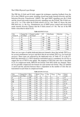
Among the M-PSK schemes, BPSK and QPSK are the most widely used. Nevertheless,
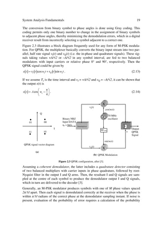
here we review only the QPSK scheme. In QPSK each transmitted symbol (Figure 2.3)
represents two input bits as follows:
Input bits Transmitted symbols
00 A cos(wct + 45°)
01 A cos(wct + 135°)
11 A cos(wct + 235°)
10 A cos(wct + 315°)](https://image.slidesharecdn.com/wileytheumtsnetworkandradioaccesstechnologyairinterfacetechniquesforfuturemobile-12712253580361-phpapp02/85/Wiley-The-Umts-Network-And-Radio-Access-Technology-Air-Interface-Techniques-For-Future-Mobile-60-320.jpg)
![Í Ý
X
vI(t)
cos(wct)
Q
70 MHz
Binary NRZ oscillator
01 00 Input DATA +
rb = bit/s Demultiplexer
I Output
90 deg.
11 10 + QPSK
Signal
sin(wct)
QPSK signal vector diagram
vQ(t)
X
(a)
(b) QPSK Modulation
Figure 2.3 QPSK configuration, after [3].
Assuming a coherent demodulator, the latter includes a quadrature detector consisting
of two balanced multipliers with carrier inputs in phase quadrature, followed by root-
Nyquist filter in the output I and Q arms. Then, the resultant I and Q signals are sam-
pled at the centre of each symbol to produce the demodulator output I and Q signals,
which in turn are delivered to the decoder [3].
Generally, an M-PSK modulator produces symbols with one of M phase values spaced
0 apart. Then each signal is demodulated correctly at the receiver when the phase is
within 0 radians of the correct phase at the demodulator sampling instant. If noise is
present, evaluation of the probability of error requires a calculation of the probability](https://image.slidesharecdn.com/wileytheumtsnetworkandradioaccesstechnologyairinterfacetechniquesforfuturemobile-12712253580361-phpapp02/85/Wiley-The-Umts-Network-And-Radio-Access-Technology-Air-Interface-Techniques-For-Future-Mobile-63-320.jpg)
![P
In the case of QPSK, symbol errors occur when the noise pushes the received phasor
into the wrong quadrant as illustrated in Figure 2.4. In this figure it is assumed that the
WUDQVPLWWHG VPERO KDV D SKDVH RI UDG FRUUHVSRQGLQJ WR WKH GHPRGXODWRU , DQG 4
values of vI = V and vQ = V volts (i.e. noise-free case). Thus, if we consider that the
noise phasors (n1 and n2) are pointing in directions that are most likely to cause errors,
then a symbol error will occur if either n1 or n2 exceeds V.
Q axis
Transmitted
n1 signal
noise
n2
Received
signal
noise
I Axis
Figure 2.4 Transmitted and received signal vectors [3].
Now, if for simplicity we also assume that a QPSK signal is transmitted without
Nyquist filtering and demodulated with hard-decisions, the probability of a correctly
demodulate symbol value is equal to the product of the probabilities that each demodu-
lator low-pass filter output lies in the correct quadrant. Then the probability that the
demodulated symbol value is correct is given by
3 = ( - 3 )( - 3 )
F H H](https://image.slidesharecdn.com/wileytheumtsnetworkandradioaccesstechnologyairinterfacetechniquesforfuturemobile-12712253580361-phpapp02/85/Wiley-The-Umts-Network-And-Radio-Access-Technology-Air-Interface-Techniques-For-Future-Mobile-65-320.jpg)

![Í R Ý
Here we found the PBER assuming that no Nyquist filtering was present. However ac-
cording to Ref. [3], this PBER also holds when root-Nyquist filters are used at the trans-
mitter and receiver under the assumption that the demodulator input energy Eb and the
noise power density No are the same for both cases.
2.1.2.3 CDMA System Performance
As noted earlier, CDMA systems tolerate more interference than typical TDMA or
FDMA systems. This implies that each additional active radio user coming into the](https://image.slidesharecdn.com/wileytheumtsnetworkandradioaccesstechnologyairinterfacetechniquesforfuturemobile-12712253580361-phpapp02/85/Wiley-The-Umts-Network-And-Radio-Access-Technology-Air-Interface-Techniques-For-Future-Mobile-75-320.jpg)
![22 The UMTS Network and Radio Access Technology
network increases the overall level of interference to the cell site receivers receiving
CDMA signals from mobile station transmitters. This depends on its received power
level at the cell site, its timing synchronization relative to other signals at the cell site,
and its specific cross-correlation with other CDMA signals. Consequently, the number
of CDMA channels in the network will depend on the level of total interference that the
system can tolerate. As a result, the FDD mode behaves as an interference limited sys-
tem, where technical design will play a key role in the overall quality and capacity per-
formance. Thus, despite advanced techniques such as multi-user detection and adaptive
antennas, a robust system will still need a good bit error probability with a higher level
of interference.
When we consider that at the cell site all users receive the same signal level assuming
Gaussian noise as interference, the modulation method has a relationship that defines
the bit error rate as a function of the Eb/No ratio. Therefore, if we know the performance
of the signal processing methods and tolerance of the digitized information to errors, we
can define the minimum Eb/No ratio for a balanced system operation. Then, if we main-
tain operation at this minimum Eb/No, we can obtain the optimum performance of the
system. From Ref. [23] we can define the relationship between the number of mobile
users M, the processing gain Gp, and the Eb/No ratio as follows:
*S
0](https://image.slidesharecdn.com/wileytheumtsnetworkandradioaccesstechnologyairinterfacetechniquesforfuturemobile-12712253580361-phpapp02/85/Wiley-The-Umts-Network-And-Radio-Access-Technology-Air-Interface-Techniques-For-Future-Mobile-76-320.jpg)
![System Analysis Fundamentals 23
formance, power control accuracy, intersystem interference), and the upper-bound theo-
retical capacity of an ideal noise-free CDMA channel has also limitations by the proc-
essing gain Gp [23].
Multiple transmissions in neighbouring CDMA cells using the same carrier frequency
cause interference, denoted by IDFWRU 7KLV HYHQW ZLOO FDXVH UHGXFWLRQ RI WKH QXPEHU
of users in a cell, because the interference from users in other cells has to be added to
WKH LQWHUIHUHQFH JHQHUDWHG E WKH RWKHU PRELOHV LQ WKH XVHU¶V FHOO PD UDQJH IURP
to 0.55. In addition to the interference factor, we also introduce the imperfect power
conWURO RU SRZHU FRQWURO DFFXUDF IDFWRU ZKLFK UDQJHV IURP WR ,QWHUIHUHQFH
FDQ EH UHGXFHG E WKH YRLFH DFWLYLW IDFWRU UDQJLQJ IURP WR ,I ZH XVH GLUHc-
tional antennas at the base station, the sectorized cell will have a sectors, the antennas
used at the cell each will radiate into a sector of 360/a degrees, resulting in an interfer-
ence imSURYHPHQW IDFWRU $YHUDJH YDOXHV IRU DQG VHFWRU FHOO](https://image.slidesharecdn.com/wileytheumtsnetworkandradioaccesstechnologyairinterfacetechniquesforfuturemobile-12712253580361-phpapp02/85/Wiley-The-Umts-Network-And-Radio-Access-Technology-Air-Interface-Techniques-For-Future-Mobile-81-320.jpg)
![DUH
0.6 and 2.55, respectively [23]. Then incorporating all the preceding factors the user
capacity equation becomes:
*S
0 ™ ™a™ ™l](https://image.slidesharecdn.com/wileytheumtsnetworkandradioaccesstechnologyairinterfacetechniquesforfuturemobile-12712253580361-phpapp02/85/Wiley-The-Umts-Network-And-Radio-Access-Technology-Air-Interface-Techniques-For-Future-Mobile-82-320.jpg)
![24 The UMTS Network and Radio Access Technology
property of the maximal length sequences implies that for an n – stage linear feedback
shift register, the sequence repetition period in clock pulses is To = 2n – 1. When a linear
feedback shift register generates a maximal sequence, then all its non-zero output se-
quences result in maximal sequences, regardless of the initial stage. A maximal se-
quence contains 2n ––1 – 1 zeros and 2n – 1 ones per period.
Other characteristics of PN sequences, e.g. properties of maximal length PN sequences,
auto-correlation, cross-correlation, and orthogonal functions are described in Ref. [23].
In the following we review additional WCDMA characteristics, such as power control
and soft handover.
2.1.2.5 Power Control Characteristics
Accurate and fast power control becomes imperative in WCDMA. It increases network
stability and prevents near-far effect (UL) or cell blocking by overpowered MSs. Open
loop or slow power control would not cope with the highly non-correlated fast fading be-
tween UL and DL as a consequence of the large frequency separation. Chapter 4 describes
the technical details of fast power control. The latter applies to both the UL and DL. In the
1st case, the BS balances the MS’s power after comparing the received Signal-to-
Interference Ratio (SIR) to a SIRtarget. In the 2nd case, we aim to provide sufficient addi-
tional power to MSs at the cell edges in order to minimise other-cell interference.
The outer loop or slow power control adjusts the BS’s reference SIRtarget based on the
needs of a single or independent radio link. It aims to maintain constant quality estab-
lished by the network through a target BER or FER for example. The RNC handles the
command steps to lower or increase the reference SIRtarget.
2.1.2.6 Soft Handovers Characteristics
While there is hard handover for carrier change or hierarchical cell transition, and inter-
system hand over to pass from FDD to TDD or GSM, in WCDMA two types of soft
handovers characterise the cell transition process. These include Softer and Soft hand-
overs. In the 1st case, a MS finds itself in the overlapped cell coverage area of two adja-
cent sectors of a BS. The MS communicates simultaneously with BS through two chan-
nels (2 DL codes) corresponding one to each sector. The MS’s rake receives and proc-
esses the two signals, where its fingers generate the necessary de-spreading codes for
each sector. The UL process occurs in the BS, where the BS receives the MS’s channel
in each sector and routes them to the same rake receiver for the typical maximal ratio
combining process under one active power control loop per connection.
In the 2nd case, i.e. soft handover, a MS finds itself in the overlapping cell coverage
area of two sectors corresponding to different BSs. Communications between MS and
BS occur simultaneously through two channels, one from each BS. In the DL, the MS
receives both signals for maximal ratio combining. In the UL, the MS code channel
arrives from both BS, and is routed to the RNC for combining, in order to allow the
same frame reliability indicator provided for outer loop power control when selecting
the best frame. Two active power control loops participate in soft handover, i.e. one for
each BS.](https://image.slidesharecdn.com/wileytheumtsnetworkandradioaccesstechnologyairinterfacetechniquesforfuturemobile-12712253580361-phpapp02/85/Wiley-The-Umts-Network-And-Radio-Access-Technology-Air-Interface-Techniques-For-Future-Mobile-84-320.jpg)
![System Analysis Fundamentals 25
While softer handover may occur only in about 10 % of links, soft handover may occur
in about 30 % of the links. Thus, for the latter provision in terms of extra power, Rake
processing, RNC transmission lines will be essential.
2.2 THE 3G COMMUNICATIONS ENVIRONMENT
This section provides dedicated reference models for the test environments cited in the
forthcoming chapters, in particular the deployment contents presented in Chapter 7.
These test environments aim to cover the range of UMTS operating environments.
Thus, the necessary parameters to identify the reference models include the test propa-
gation environments, traffic conditions and user information rate for reference voice and
data services. It also presents some performance objectives and criteria for each operat-
ing environment.
The test operating environments are direct extracts from the recommendations consid-
ered for the evaluation process of the Radio Transmission Technologies (RTTs) submit-
ted to ETSI and ITU as UTRA candidate solutions. Thus, the contents bring together or
are based entirely on the specifications outlined in Refs. [1–4].
2.2.1 Mapping High Level Requirements onto Test Environments
This section maps high level service requirements summarized in Chapter 1 onto test en-
vironments described in the next sections. The mapping identifies the maximum user bit
rate in each test environment, together with the maximum speed, expected range and as-
sociated wide-band channel model. Table 2.1 illustrates the suggested reference values.
Table 2.1 Radio Transmission Test Environments [2]
High level Maximal bit rate Maximal Test environment Cell cover-
description speed channel models age
Rural outdoor 144 kbit/s 500 km/h Vehicular channel A B Macrocell
Suburban outdoor 384 kbit/s 120 km/h Outdoor to indoor and Microcell
pedestrian channel A B
Vehicular channel A Macrocell
Indoor/ 2048 kbit/s 10 km/h Indoor channel A B Picocell
Low range out- Outdoor to indoor and Microcell
door pedestrian channel A
2.2.1.1 Reference Services
The UMTS minimum set of services to appropriately characterize bearers include:
ranges of supported data rates, BER requirements, one way delay requirements, activity
factor and traffic models. The forthcoming section covers traffic models and Table 2.2
provides example values for access reference services, such as: Speech, Low Delay
Data (LDD), Long delay Circuit Switched Data (LCD), Unrestricted Delay Data
(UDD). The latter corresponds to connectionless data for packet services; 12.2 kbps
corresponds to AMR rates not necessarily part of the early test recommendations [2].](https://image.slidesharecdn.com/wileytheumtsnetworkandradioaccesstechnologyairinterfacetechniquesforfuturemobile-12712253580361-phpapp02/85/Wiley-The-Umts-Network-And-Radio-Access-Technology-Air-Interface-Techniques-For-Future-Mobile-85-320.jpg)
![26 The UMTS Network and Radio Access Technology
Table 2.2 Reference Data Rates
Test environments Indoor office Outdoor to indoor Vehicular Vehicular
and pedestrian 120 km/h 500 km/h
Speech (kbps) 8, 12.2 8, 12.2 8, 12.2 8, 12.2
BER ˆ10–3 ˆ10–3 ˆ10–3 ˆ10–3
Delay (ms 20 20 ms 20 20
Activity (%) 50 50% 50 50
LDD data (kbps) 144, 384, 2048 64, 144, 384 32, 144, 384 32, 144
BER ˆ10–6 ˆ10–6 ˆ10–6 ˆ10–6
Delay (ms) 50 50 50 50
Activity (%) 100 100 100 100
UDD data (packet) See Section See Section See Section See Section
connection-less 2.2.8.1 and 2.2.8.1 and Table 2.2.8.1 and 2.2.8.1 and
information types Table 2.7 2.7 Table 2.7 Table 2.7
LCD data (kbps) 144, 384, 2048 64, 144, 384 32, 144, 384 32, 144
BER ˆ10–6 ˆ10–6 ˆ10–6 ˆ10–6
Delay (ms) 300 300 300 300
Activity (%) 100 100 100 100
2.2.2 Channel Types
As a global standard, UMTS aims for a broad range of environment characteristics, e.g.
large and small cities, tropical, rural, and desert areas. Reference parameters describing
the propagation models for these areas include:
1. time delay-spread with its structure and its statistical variability (e.g. probability
distribution of time delay spread);
2. geometrical path loss rule (e.g. R–4) and excess path loss;
3. shadow fading and multi-path fading characteristics (e.g. Doppler spectrum, Rician
vs. Rayleigh) for the envelope of channels; and
4. operating radio frequency.
Characterization of rapid fading variation occurs by the channel impulse response,
where response modelling takes place using a tapped delay line implementation. The
Doppler spectrum characterizes the tap variability. These environments are represented
in terms of propagation from [2] by: indoor office, outdoor to indoor and pedestrian,
vehicular, and mixed.
2.2.3 Indoor Office
This environment has small cells and low transmit powers, where both BSs and pedes-
trian users remain indoors, with path loss rule varying due to scatter and attenuation by
walls, floors, and metallic structures, e.g. partitions and filing cabinets, all producing
some type of shadowing effects. These effects include: log-normal shadow fading with
standard deviation of 12 dB, and fading ranges from Rician to Rayleigh, with Doppler
frequency offsets set by walking speeds.
The indoor office path loss is based on the COST6 231 model; this low increase of path loss
versus distance is a worst case from the interference point of view and is defined as follows:
_______
6 COST 231 Final Report (e.g. propagation environments) , Commission of the European Communities.](https://image.slidesharecdn.com/wileytheumtsnetworkandradioaccesstechnologyairinterfacetechniquesforfuturemobile-12712253580361-phpapp02/85/Wiley-The-Umts-Network-And-Radio-Access-Technology-Air-Interface-Techniques-For-Future-Mobile-86-320.jpg)
![where LFS is the free space between transmitter and receiver, Lc is the constant loss, kwi
is the number of penetrated walls of type i, n is the number of penetrated floors, Lwi is
the loss of wall type i, Lf is the loss between adjacent floors, and b is the empirical pa-
rameter. Lc normally is set to 37 dB. n = 4 is the average for an indoor office environ-
ment. For capacity calculations in moderately pessimistic environments, the model can
be modified to n = 3.
Table 2.3 Weighted Average for Loss Categories Indoor Environment [2]
Loss cate- Description Factor
gory (dB)
Lf Typical floor structures (i.e. offices)
- hollow pot tiles 18.3
- reinforced concrete
- thickness typ. 30 cm
Lw1 Light internal walls
- plasterboard 3.4
- walls with large numbers of holes (e.g. windows)
Lw2 Internal walls
- concrete, brick 6.9
- minimum number of holes
Under the simplifying assumptions of the office environment the indoor path loss model
has the following form:
Q +](https://image.slidesharecdn.com/wileytheumtsnetworkandradioaccesstechnologyairinterfacetechniquesforfuturemobile-12712253580361-phpapp02/85/Wiley-The-Umts-Network-And-Radio-Access-Technology-Air-Interface-Techniques-For-Future-Mobile-91-320.jpg)
![Ã
where R is the transmitter-receiver separation given in metres and n is the number of
floors in the path. L shall in no circumstances be less than free space loss. A log-normal
shadow fading standard deviation of 12 dB can be expected.
Physical deployment
The specific assumptions about the indoor physical deployment environment can be
summarized from [2] as: area per floor = 5000 m2, number of floors = 3, room = 20 ™
10 ™ 3 (m), corridor = 100 ™ 5 ™ 3 (m), log-normal standard deviation = 12 (dB), MS
velocity = 3 (km/h). Figure 2.5 illustrates a default deployment scheme, where base
stations use omnidirectional antennas. For spectrum efficiency evaluation, quality statis-
tics should only be collected in the middle floor. See the mobility model in [2].](https://image.slidesharecdn.com/wileytheumtsnetworkandradioaccesstechnologyairinterfacetechniquesforfuturemobile-12712253580361-phpapp02/85/Wiley-The-Umts-Network-And-Radio-Access-Technology-Air-Interface-Techniques-For-Future-Mobile-96-320.jpg)
![Í [ Ý
Dhm is the difference between the mean building height and the mobile antenna height;
x is the horizontal distance between the mobile and the diffracting edges [2].
For the general model, the multiple screen diffraction loss from the base antennas due to
propagation past rows of buildings is:
/PVG = -ORJ 40](https://image.slidesharecdn.com/wileytheumtsnetworkandradioaccesstechnologyairinterfacetechniquesforfuturemobile-12712253580361-phpapp02/85/Wiley-The-Umts-Network-And-Radio-Access-Technology-Air-Interface-Techniques-For-Future-Mobile-104-320.jpg)
![where Qm is a factor dependent on the relative height of the base station antenna as be-
ing either at, below or above the mean building heights [13,14].
In this case the base-station antenna height is near mean rooftop level, then:
G
40 =](https://image.slidesharecdn.com/wileytheumtsnetworkandradioaccesstechnologyairinterfacetechniquesforfuturemobile-12712253580361-phpapp02/85/Wiley-The-Umts-Network-And-Radio-Access-Technology-Air-Interface-Techniques-For-Future-Mobile-105-320.jpg)
![where R is the base station–mobile station separation in kilometres; f is the carrier fre-
quency of 2000 in MHz for UMTS band application. L shall in no circumstances be less
than free space loss. This model applies to the non-line-of-sight (NLOS) case only and
describes worse case propagation assuming log-normal shadow fading with a standard
deviation of 10 dB for outdoor users and 12 dB for indoor users. The average building
penetration loss is 12 dB with a standard deviation of 8 dB [2].
A more detailed model uses a recursive approach [15] that calculates the path loss as a
sum of LOS and NLOS segments. The shortest path along streets between the BS and
the MS has to be found within the Manhattan environment and the path loss (dB) is
given by:
pG Q
/ = ORJ](https://image.slidesharecdn.com/wileytheumtsnetworkandradioaccesstechnologyairinterfacetechniquesforfuturemobile-12712253580361-phpapp02/85/Wiley-The-Umts-Network-And-Radio-Access-Technology-Air-Interface-Techniques-For-Future-Mobile-110-320.jpg)
![This path loss model applies only to microcell coverage with antenna located below the
roof-top. When the urban structure has macrocell coverage, the first path loss case ap-
plies [2].
Physical Deployment
The same test service requirements of the preceding section (indoor) apply for the out-
door-to-indoor pedestrian environment. The specific assumptions about the physical
deployment environment include:
œ Indoor: building penetration loss = 12 dB, standard deviation = 8, log-normal stan-
dard deviation = 10 and MS velocity = 3 km.
œ Outdoor: building penetration loss = NA, log-normal standard deviation = 10, MS
velocity = 3 km.
A Manhattan-like structure defined for the outdoor to indoor and pedestrian environ-
ment can be applied with following assumptions: 6.5 km2, 200 ™ 200 m block, 30 m
street width, and 10 m BS height. Figure 2.6 illustrates the default deployment scheme
with BS using omni-directional antennas, where expected quality statistics would only
arise from among cells marked with a T. See the mobility model in Ref. [2].](https://image.slidesharecdn.com/wileytheumtsnetworkandradioaccesstechnologyairinterfacetechniquesforfuturemobile-12712253580361-phpapp02/85/Wiley-The-Umts-Network-And-Radio-Access-Technology-Air-Interface-Techniques-For-Future-Mobile-116-320.jpg)
![32 The UMTS Network and Radio Access Technology
In the building environment, measurements [16] showed that the path loss slope be-
haves as a linear function of the base station antenna height relative to the average roof-
top Dhb. Then, the above path loss equation can be defined as:
Î
( ) Þ
ÎË l Û Þ
Î l Ë Û Þ
DKE G l
- ORJ Ï( ) ß
/ = -ORJ ÏÌ Ü ß - ORJ Ï Ì - Ü ß
ÏÍ p5 Ý ß
Ï p U Í q p + q Ý ß
Ï -
5 - ™ DKE](https://image.slidesharecdn.com/wileytheumtsnetworkandradioaccesstechnologyairinterfacetechniquesforfuturemobile-12712253580361-phpapp02/85/Wiley-The-Umts-Network-And-Radio-Access-Technology-Air-Interface-Techniques-For-Future-Mobile-120-320.jpg)
![L shall in no circumstances be less than the free space loss. This model applies to the
Non-Line of Sight (NLOS) case only and describes the worse case propagation. Log-
normal shadow fading with 10 dB standard deviation are assumed in both urban and
suburban areas [2]. The path loss model is valid for a range of Dhb from 0 to 50 m.
Physical Deployment
When assuming a cell radius of 2000 m, services up to 144 kbit/s apply; and with a cell
radius of 500, services above 144 kbps (e.g. 384 kbps) apply. If the BS antenna height
remains above the average roof top height of 15 m, a hexagonal cell lay out with dis-
tances between base stations equal to 6 km can serve as reference. Figure 2.7 illustrates
this type of tri-sectored cells using the GSM based antenna pattern shown in Figure 2.8.
Mobility Model
The vehicular reference mobility model uses a pseudorandom mobility model with
semi-directed trajectories, the mobile’s position gets updated according to the de-
correlation length and direction can change at each position update following a given
probability within a sector. For a reference example, we can assume constant mobile
speeds of 120 km/h, with a direction probability change at position update of 0.2, and a
maximal angle for direction update of 45°. Mobiles get uniformly distributed on the
map and their direction randomly chosen at initialization [2].](https://image.slidesharecdn.com/wileytheumtsnetworkandradioaccesstechnologyairinterfacetechniquesforfuturemobile-12712253580361-phpapp02/85/Wiley-The-Umts-Network-And-Radio-Access-Technology-Air-Interface-Techniques-For-Future-Mobile-130-320.jpg)
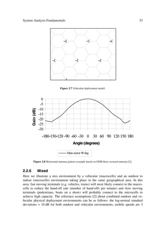
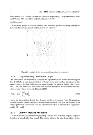
![System Analysis Fundamentals 33
†v‡rÆrƒÃ2Ã%Ãx€ÃÃ
Figure 2.7 Vehicular deployment model.
Gain (dB)
Angle (degrees)
0DLQ VHFWRU GHJ
Figure 2.8 Horizontal antenna pattern example based on GSM three sectored antenna [2].
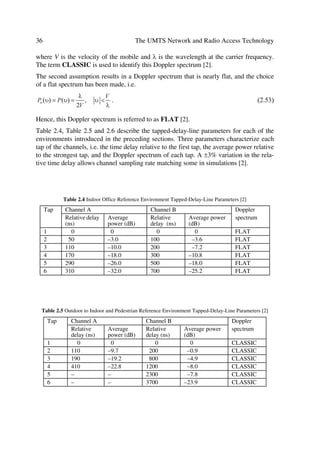
2.2.6 Mixed
Here we illustrate a mix environment by a vehicular (macrocells) and an outdoor to
indoor (microcells) environment taking place in the same geographical area. In this
area, fast moving terminals (e.g. vehicles, trains) will most likely connect to the macro-
cells to reduce the hand-off rate (number of hand-offs per minute) and slow moving
terminals (pedestrians, boats on a shore) will probably connect to the microcells to
achieve high capacity. The reference assumptions [2] about combined outdoor and ve-
hicular physical deployment environments can be as follows: the log-normal standard
deviations = 10 dB for both outdoor and vehicular environments, mobile speeds are 3](https://image.slidesharecdn.com/wileytheumtsnetworkandradioaccesstechnologyairinterfacetechniquesforfuturemobile-12712253580361-phpapp02/85/Wiley-The-Umts-Network-And-Radio-Access-Technology-Air-Interface-Techniques-For-Future-Mobile-131-320.jpg)
![34 The UMTS Network and Radio Access Technology
km/h and 80–120 km/h for outdoor and vehicular, respectively. The proportions of users
are 60% and 40% for outdoor and vehicular, respectively.
Mobility Model
The mobility model will follow outdoor and vehicular patterns allowing appropriate
handover between macrocells and microcells for all users.
Figure 2.9 Mixed physical environment and proposed deployment model.
2.2.6.1 Long-term Fading Decorrelation Length
We characterize the log-normal fading in the logarithmic scale around the mean path
loss L (dB) by a Gaussian distribution with zero mean and standard deviation. In this
context, due to the slow fading process versus distance Dx, adjacent fading values corre-
late. Then, the normalized auto-correlation function R(Dx) can be described with suffi-
cient accuracy by an exponential function [17].
Ë D[ Û
5 D[](https://image.slidesharecdn.com/wileytheumtsnetworkandradioaccesstechnologyairinterfacetechniquesforfuturemobile-12712253580361-phpapp02/85/Wiley-The-Umts-Network-And-Radio-Access-Technology-Air-Interface-Techniques-For-Future-Mobile-132-320.jpg)
![System Analysis Fundamentals 35
first tap, the average power relative to the strongest tap, and the Doppler spectrum of
each tap characterize the model. Most of the time delay spreads are relatively small, but
occasionally, there are worst case multi-path characteristics that lead to larger delay
spreads. Here we consider the worst case. Two multi-path channels capture this delay
spread better than a single tapped delay line. The reference simulation channel model
can use a discrete wide sense stationary uncorrelated scattering (WSSUS) channel
model, where the sum of delay replicas represents the received signal of the input signal
weighted by independent zero-mean complex Gaussian time variant processes. Hence,
if z(t) and w(t) denote the complex low pass representations of the channel input and
output, respectively, then [2]
1
ZW](https://image.slidesharecdn.com/wileytheumtsnetworkandradioaccesstechnologyairinterfacetechniquesforfuturemobile-12712253580361-phpapp02/85/Wiley-The-Umts-Network-And-Radio-Access-Technology-Air-Interface-Techniques-For-Future-Mobile-135-320.jpg)
![] W - tQ](https://image.slidesharecdn.com/wileytheumtsnetworkandradioaccesstechnologyairinterfacetechniquesforfuturemobile-12712253580361-phpapp02/85/Wiley-The-Umts-Network-And-Radio-Access-Technology-Air-Interface-Techniques-For-Future-Mobile-137-320.jpg)
![Í : : Ý
where W is the bandwidth of the transmitted signal.
Generally, each ray has a different Doppler shift corresponding to a different value of
the cosine of the angle between the ray direction and the velocity vector. Which means
that we can assume: first, very large number of receive-rays arrive uniformly distributed
in azimuth at the MS and at zero elevation for each delay interval for outdoor channels7.
At the BS in general the received rays arrive in a limited range in azimuth. Second, for
indoor channels8 a very large number of receive-rays arrive uniformly distributed in
elevation and azimuth for each delay interval at the BS.
The first assumption matches the ones made in by Clarke [18] and Jakes [19] in narrow
band channel modelling. Thus the same Doppler spectrum will result, i.e.
9
3Q u](https://image.slidesharecdn.com/wileytheumtsnetworkandradioaccesstechnologyairinterfacetechniquesforfuturemobile-12712253580361-phpapp02/85/Wiley-The-Umts-Network-And-Radio-Access-Technology-Air-Interface-Techniques-For-Future-Mobile-139-320.jpg)

![36 The UMTS Network and Radio Access Technology
where V is the velocity of the mobile and l is the wavelength at the carrier frequency.
The term CLASSIC is used to identify this Doppler spectrum [2].
The second assumption results in a Doppler spectrum that is nearly flat, and the choice
of a flat spectrum has been made, i.e.
l 9
3Q u](https://image.slidesharecdn.com/wileytheumtsnetworkandradioaccesstechnologyairinterfacetechniquesforfuturemobile-12712253580361-phpapp02/85/Wiley-The-Umts-Network-And-Radio-Access-Technology-Air-Interface-Techniques-For-Future-Mobile-143-320.jpg)
![9 l
Hence, this Doppler spectrum is referred to as FLAT [2].
Table 2.4, Table 2.5 and 2.6 describe the tapped-delay-line parameters for each of the
environments introduced in the preceding sections. Three parameters characterize each
tap of the channels, i.e. the time delay relative to the first tap, the average power relative
to the strongest tap, and the Doppler spectrum of each tap. A –3% variation in the rela-
tive time delay allows channel sampling rate matching some in simulations [2].
Table 2.4 Indoor Office Reference Environment Tapped-Delay-Line Parameters [2]
Tap Channel A Channel B Doppler
Relative delay Average Relative Average power spectrum
(ns) power (dB) delay (ns) (dB)
1 0 0 0 0 FLAT
2 50 –3.0 100 –3.6 FLAT
3 110 –10.0 200 –7.2 FLAT
4 170 –18.0 300 –10.8 FLAT
5 290 –26.0 500 –18.0 FLAT
6 310 –32.0 700 –25.2 FLAT
Table 2.5 Outdoor to Indoor and Pedestrian Reference Environment Tapped-Delay-Line Parameters [2]
Tap Channel A Channel B Doppler
Relative Average Relative Average power spectrum
delay (ns) power (dB) delay (ns) (dB)
1 0 0 0 0 CLASSIC
2 110 –9.7 200 –0.9 CLASSIC
3 190 –19.2 800 –4.9 CLASSIC
4 410 –22.8 1200 –8.0 CLASSIC
5 – – 2300 –7.8 CLASSIC
6 – – 3700 –23.9 CLASSIC](https://image.slidesharecdn.com/wileytheumtsnetworkandradioaccesstechnologyairinterfacetechniquesforfuturemobile-12712253580361-phpapp02/85/Wiley-The-Umts-Network-And-Radio-Access-Technology-Air-Interface-Techniques-For-Future-Mobile-146-320.jpg)
![System Analysis Fundamentals 37
Table 2.6 Vehicular Reference Environment, High Antenna, Tapped-Delay-Line Parameters [2]
Tap Channel A Channel B Doppler
Relative Average Relative delay Average spectrum
delay (ns) power (dB) (ns) power (dB)
1 0 0.0 0 –2.5 CLASSIC
2 310 –1.0 300 0 CLASSIC
3 710 –9.0 8900 –12.8 CLASSIC
4 1090 –10.0 12900 –10.0 CLASSIC
5 1730 –15.0 17100 –25.2 CLASSIC
6 2510 –20.0 20000 –16.0 CLASSIC
2.2.8 7UDIILF 7SHV DQG 3URSDJDWLRQ 0RGHOV
We can represent real time services (e.g. speech and CS data services) by generating
calls according to a Poisson process assuming a mean call duration of 120 s. The speech
would an on-off model, with activity and silent periods being generated by an exponen-
tial distribution. The mean value for active and silence periods is 3 s and independent of
the up and downlink, and both are exponentially distributed. For circuit switched data
services, we can assume a traffic model with constant bit rate model and 100% activity.
2.2.8.1 Packet or Non-real Time Services
We can represent non-real time services by a WWW browsing session consisting of a
sequence of packet calls. We only consider the packets from a source, which may be at
either end of the link but not simultaneously. A subscriber may initiate a packet call
when requesting an information entity. During this call several packets may be gener-
ated, which means that the packet call constitutes a sequence of packets bursts [20,21].
Figure 2.10 illustrates the bursts during the packet call typically seen in fixed network
packet transmissions.
D†‡hpr†Ã‚sÃhpxr‡ Gh†‡Ãƒhpxr‡Ãh……v‰hyÇ‚
h……v‰hy†Ã‡‚Ã7TÃiˆssr… 7TÃiˆssr…
6Ãhpxr‡Ãphyy
‡
6Ãhpxr‡Ã†r…‰vprÆr††v‚
Av…†‡Ãƒhpxr‡Ãh……v‰hy
‡‚Ã7TÃiˆssr…
Figure 2.10 Packet service session characteristics.
The behaviour of Figure 2.10 can be modelled through the following parameters:
- Session arrival process “ Poisson process
- Number of packet calls per session “ 1 SF ³ *HRPm 1SF](https://image.slidesharecdn.com/wileytheumtsnetworkandradioaccesstechnologyairinterfacetechniquesforfuturemobile-12712253580361-phpapp02/85/Wiley-The-Umts-Network-And-Radio-Access-Technology-Air-Interface-Techniques-For-Future-Mobile-147-320.jpg)
![Ôm = N a a
Ô a -
Ô
Ôs = N a
a
Ô ( a - )( a - )
Ó
Packet_Size is defined by the following formula:
3DFNHWB6L]H = PLQ 3 P](https://image.slidesharecdn.com/wileytheumtsnetworkandradioaccesstechnologyairinterfacetechniquesforfuturemobile-12712253580361-phpapp02/85/Wiley-The-Umts-Network-And-Radio-Access-Technology-Air-Interface-Techniques-For-Future-Mobile-154-320.jpg)
![with the parameters above the average size: mn = 480 bytes [2,20,21] indicates that ac-
cording to the values for a and k in the Pareto distribution, the average packet size µ is
480 bytes. Average requested file size is mNd ™ µ = 25 ™ 480 bytes 12 kbytes. The
inter-arrival time is adjusted in order to get different average bit rates at the source
level. Table 2.7 illustrates characteristics of connectionless information rates for WWW
from [20].](https://image.slidesharecdn.com/wileytheumtsnetworkandradioaccesstechnologyairinterfacetechniquesforfuturemobile-12712253580361-phpapp02/85/Wiley-The-Umts-Network-And-Radio-Access-Technology-Air-Interface-Techniques-For-Future-Mobile-160-320.jpg)
![System Analysis Fundamentals 39
Table 2.7 Characteristics of Connection-Less Information Types [20]
Packet based infor- Avg. no. of Avg. reading Avg. amount of Avg. inter-arrival Parameters
mation rates, e.g. packet calls time between packets within a time between for packet size
Internet services in a session packet calls (s) packet call pakets (s)9 distribution
WWW surfing 5 412 25 0.5 k = 81.5
UDD 8 kbit/s (= 1.1
WWW surfing 5 412 25 0.125 k = 81.5
UDD 32 kbit/s (= 1.1
WWW surfing 5 412 25 0.0625 k = 81.5
UDD 64 kbit/s (= 1.1
WWW surfing 5 412 25 0.0277 k = 81.5
UDD 144 kbit/s (= 1.1
WWW surfing 5 412 25 0.0104 k = 81.5
UDD 384 kbit/s (= 1.1
WWW surfing 5 412 25 0.00195 k = 81.5
UDD 2048 kbit/s a = 1.1
2.3 CONCLUDING REMARKS
This chapter summarizes the essential background to investigate the UTRA physical
layer and its impact on its architecture. It has provided the reference models to represent
the communication environments and the signal processing issues. It was not the aim of
the author to cover the different topics in depth but to set them as review points for fur-
ther study when required.
References
[1] TG32 UMTS – Radio Requirements.
[2] High Level Requirements Relevant for the Definition of the UTRA Concept, v3.0.1, 1998-
10.
[3] TS 101 111 (UMTS 21.01) Universal Mobile Telecommunication System (UMTS); Overall
Requirements on the Radio Interface(s) of the UMTS.
[4] Draft New Recommendation ITU-R M.[FPLMTS.REVAL] Guidelines for Evaluation of
Radio Transmission Technologies for IMT-200/FPLMTS.
[5] Haykin, S., Communications Systems, Wiley, New York, 1983.
[6] Shanmugam, K.S., Digital and Analog Communication Systems, Wiley, New York, 1979.
[7] Schwartz, M., Information Transmission, Modulation, and Noise, McGraw-Hill, New
York, 1970.
[8] Steele, R. Mobile Radio Communications, IEEE Press, Piscataway, NJ, 1994.
[9] Yang, S.C. CDMA RF System Engineering, Artech House, Norwood, MA, 1998.
_______
9
The different interarrival times correspond to average bit rates of 8, 32, 64, 144, 384 and 2048 kbit/s.](https://image.slidesharecdn.com/wileytheumtsnetworkandradioaccesstechnologyairinterfacetechniquesforfuturemobile-12712253580361-phpapp02/85/Wiley-The-Umts-Network-And-Radio-Access-Technology-Air-Interface-Techniques-For-Future-Mobile-161-320.jpg)
![40 The UMTS Network and Radio Access Technology
[10] Viterbi, A. Principles of Spread Spectrum Communication, Addison-Wesley, 1997.
[11] Cooper, G. and McGillem, C. Modern Communications and Spread Spectrum, McGraw-
Hill, New York, 1998.
[12] Dixon, R. Spread Spectrum Systems with Commercial Applications, Wiley, New York,
1994.
[13] Xia, H.H. and Bertoni, H.L., “Diffraction of Cylindrical and Plane Waves By an Array of
Absorbing Half Screens”, IEEE Trans. Antennas Propagation, 40(2), 1992, 170–177.
[14] Maciel, L.R., Bertoni, H.L. and Xia, H.H., “Unified Approach to Prediction of Propagation
Over Buildings for All Ranges of Base Station Antenna Height”, IEEE Trans. Vehicular
Technol., 42(1), 1993, 41–45.
[15] J.E. Berg , “A Recursive Method For Street Microcell Path Loss Calculations”, PIMRC
‘95, Vol. 1, 1995, 140–143.
[16] Xia, H.H. et al., “Microcellular Propagation Characteristics for Personal Communications
in Urban and Suburban environments”, IEEE Trans. Vehicular Technol., 43(3), 1994, 743–
752.
[17] Gudmundson, M., “Correlation Model for Shadow Fading in Mobile Radio Systems”, Elec-
tron. Lett., 27(23), 1991, 2145–2146.
[18] Clark, R.H. “A Statistical Theory of Mobile Reception,” Bell System Tech. J., 47, 1968,
957–1000.
[19] Jakes, W.C. (Editor), Microwave Mobile Communications, Wiley, New York, 1974.
[20] Anderlind, E. and Zander, J. “A Traffic Model for Non-Real-Time Data Users in a Wireless
Radio Network”, IEEE Commun. Lett., 1(2), 1997.
[21] Miltiades E et al. “A Multiuser Descriptive Traffic Source Model”, IEEE Trans. Commun.,
44(10), 1996.
[22] Shannon, C.E., “Communications in the Presence of Noise,” Proc. IRE, 37, 1949, 10–21.
[23] Garg, V.K., Smolik, K. and Wilkes, J.E. Applications of CDMA in Wireless/Personal
Communications, Prentice Hall, New Jersey, 1997.](https://image.slidesharecdn.com/wileytheumtsnetworkandradioaccesstechnologyairinterfacetechniquesforfuturemobile-12712253580361-phpapp02/85/Wiley-The-Umts-Network-And-Radio-Access-Technology-Air-Interface-Techniques-For-Future-Mobile-162-320.jpg)
![The UMTS Network and Radio Access Technology: Air Interface Techniques for Future Mobile Systems
Jonathan P. Castro
Copyright © 2001 John Wiley Sons Ltd
Print ISBN 0-471-81375-3 Online ISBN 0-470-84172-9
THE UMTS DEVELOPMENT
PLATFORM
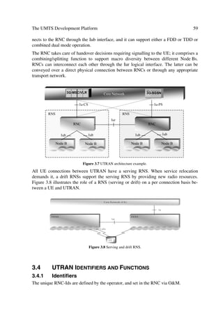
3.1 ARCHITECTURE AND DEPLOYMENT SCENARIOS
The architecture at the domain and functional levels, as well as the deployment scenar-
ios are presented based on the 3GPP (ETSI) specifications noted in [1,2]. The terminol-
ogy and basic principles are kept for consistency with a simplified approach in some
cases, and for a pragmatic representation of the subject in others.
3.1.1 The UMTS High Level System Architecture
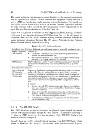
3.1.1.1 The UMTS Domains
Figure 3.1 illustrates the different UMTS domains. The identified domains imply the
evolution of current or existing network infrastructures, but do not exclude new ones.
The Core Network (CN) domain can evolve for example from the GSM, N-ISDN, B-
ISDN, and PDN infrastructures.
C‚€r
Ir‡‚…x
9‚€hv
baˆd
86,0 8ˆ H‚ivyr Vˆ 6ppr†† Dˆ Tr…‰vt b`ˆd U…h†v‡
'RPDLQ @„ˆvƒ€r‡ Ir‡‚…x Ir‡‚…x Ir‡‚…x
9‚€hv 9‚€hv 9‚€hv 9‚€hv
8‚…rÃIr‡‚…xÃ9‚€hv
V†r…Ã@„ˆvƒ€r‡Ã9‚€hv Ds…h†‡…ˆp‡ˆ…rÃ9‚€hv
8ˆ 2ÃSrsr…rprÂv‡Ãir‡rrÃVTDHÃhqÃH@
Dˆ 2ÃSrsr…rprÂv‡Ãir‡rrÃ6ppr††ÃhqÃTr…‰vtÃIr‡‚…xÃq‚€hv†
Vˆ 2ÃSrsr…rprÂv‡Ãir‡rrÃV†r…Ã@„ˆvƒ€r‡ÃhqÃDs…h†‡…ˆp‡ˆ…rÃq‚€hv†ÃVHUTÃ…hqv‚Ãv‡r…shpr
b`ˆd 2ÃSrsr…rprÂv‡Ãir‡rrÃTr…‰vtÃhqÃU…h†v‡ÃIr‡‚…xÃq‚€hv†
baˆd 2ÃSrsr…rprÂv‡Ãir‡rrÃTr…‰vtÃhqÃC‚€rÃIr‡‚…xÃq‚€hv†
Figure 3.1 UMTS architecture domains and reference points.](https://image.slidesharecdn.com/wileytheumtsnetworkandradioaccesstechnologyairinterfacetechniquesforfuturemobile-12712253580361-phpapp02/85/Wiley-The-Umts-Network-And-Radio-Access-Technology-Air-Interface-Techniques-For-Future-Mobile-163-320.jpg)
![42 The UMTS Network and Radio Access Technology
The generic architecture incorporates two main domains, i.e. the user equipment domain
and the infrastructure domain. The first concerns the equipment used by the user to
access UMTS services having a radio interface to the infrastructure. The second con-
sists of the physical nodes, which perform the various functions required to terminate
the radio interface and to support the telecommunication services requirements of the
users. The rest of the sub-domains are defined in Table 3.1.
Figure 3.16 in Appendix A illustrates the four (Application, Home, Serving, and Trans-
port) strata. It also shows the integrated UMTS functional flow, i.e. the interactions be-
tween the USIM, MT/ME, Access Network, Serving Network and Home Network do-
mains, including interactions between TE, MT, Access Network, Serving Network,
Transit Network domains and the Remote Party.
Table 3.1 The UMTS Architecture Domains
USER EQUIPMENT DOMAINS: dual mode and multi-mode handsets, removable smart cards, etc.
Mobile Equipment Consists of:
(ME) domain œ The Mobile Termination (MT) entity performing the radio trans-
mission and related functions, and
œ the Terminal Equipment (TE) entity containing the end-to-end ap-
plication, (e.g. a laptop connected to a handset).
USIM domain The User Services Identity Modulo (USIM) domain contains data and
procedures to unambiguously and securely identify itself, (e.g. smart
card)
INFRASTRUCTURE DOMAINS
Access Network Consists of the physical entities managing the access network resources
(AN) domain and provides the users with mechanisms to access the core network
Core Network Consists of the physical entities providing support for the network fea-
(CN) domain tures and telecommunication services; e.g. management of user location
information, control of network features and services, switching and
transmission mechanisms for signalling and for user generated informa-
tion.
It includes:
1. Serving Network (SN) domain representing the core network func-
tions local to the user’s access point and thus their location changes
when the user moves.
2. Home Network (HN) domain representing the core functions con-
ducted at a permanent location regardless of the user’s access point.
The USIM is related by subscription to the HN.
3. Transit Network (TN) domain, which is the CN part between the
SN and the remote party.
3.1.1.2 The IMT 2000 Family
The UMTS high level architecture integrates the physical aspects through the domain
concept and functional aspects through the strata concept. The separation according to
[1] allows a UMTS network to fit within the context of the IMT 2000 family of net-
works as illustrated in Figure 3.2.
Basically there are two CN options for the air interface of the IMT 2000 family of net-
works, i.e. GSM and IS-41 networks. The first one, which also includes the IP packet](https://image.slidesharecdn.com/wileytheumtsnetworkandradioaccesstechnologyairinterfacetechniquesforfuturemobile-12712253580361-phpapp02/85/Wiley-The-Umts-Network-And-Radio-Access-Technology-Air-Interface-Techniques-For-Future-Mobile-164-320.jpg)
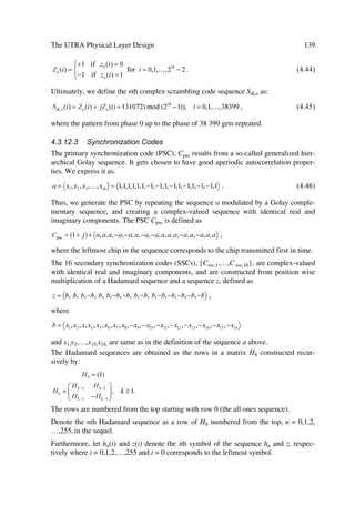
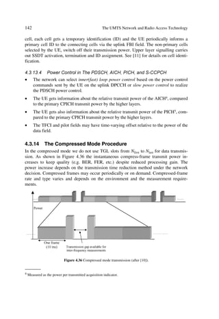
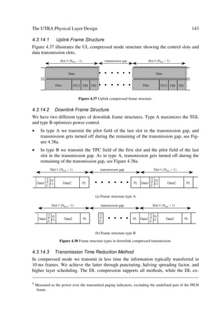
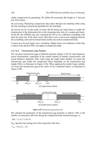
![The UMTS Development Platform 49
In conclusion, we can say that the two critical interfaces that UMTS introduces to the
CN are primarily the Iu and IP. These interfaces add new dimension to the existing
GSM infrastructures besides enriching the type of links a CN may have.
In the following we cover the essential transition steps in terms of the 3G architecture
requirements.
3.2.2 Key Release 99 Architectural Requirements
The general working assumptions for Release 99 (R99), which cover the phase 1
UMTS/Release ’99 GSM standards and reflecting in part the elements illustrated in
Figure 3.3, can be summarized from [3] as follows:
œ a Core Network based on an evolved 2G MSC and an evolved SGSN
œ an optionally evolved Gs interface
œ Mobile IPv4 with Foreign Agent (FA) care-of addresses to end-users over the
UMTS/GPRS network, where the FA is located in the GGSN.
œ class A GSM mobiles.
œ Transcoder location shall be according to the “Evolution of the GSM platform to-
wards UMTS” outlined in 3G TS 23.930
œ UMTS/IMT 2000 Phase1 (R99) network architecture and standards shall allow the
operator to choose between Integrated and Separated CNs for transmission (includ-
ing L2)
œ The UMTS standard shall allow for both separated and combined MSC/VLR and
SGSN configurations.
œ The UE shall be able to handle separated or combined MSCs and SGSNs.
œ There can be several user planes to these CN nodes.
The following general concepts should be followed:
œ Separate the layer 3 control signalling from the layer 2 transport discussion (do not
optimize layer 3 for one layer 2 technology).
œ MSC-MSC layer 3 call control is out of scope of standardization in SMG.
œ As future evolution may lead to the migration of some services from the CS do-
main to the PS domain without changes to the associated higher-layer protocols or
functions. UMTS release 99 shall provide the flexibility to do this in a way that is
backwards compatible with release 99 UEs, provided this does not introduce sig-
nificant new complexity or requirements in the system.
3.2.3 The R99 Core Network Synthesis
In the preceding section we have already covered the evolution of the CN. However,
here we are summarizing them again in the light of the R99 to provide a concise back-
ground for R00 introduced in Chapter 9. The synthesis here considers the classical 2G
(GSM) type CN architecture evolving to 3G CN. However, some suppliers may already](https://image.slidesharecdn.com/wileytheumtsnetworkandradioaccesstechnologyairinterfacetechniquesforfuturemobile-12712253580361-phpapp02/85/Wiley-The-Umts-Network-And-Radio-Access-Technology-Air-Interface-Techniques-For-Future-Mobile-173-320.jpg)
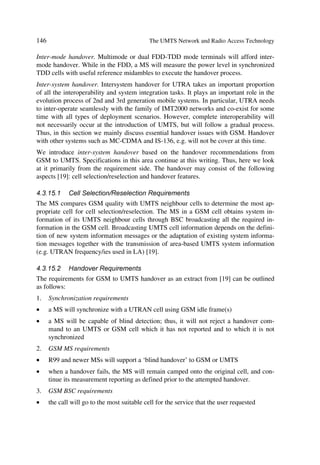
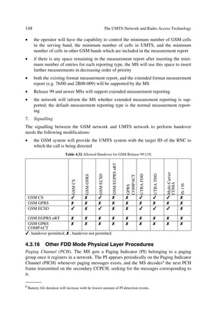
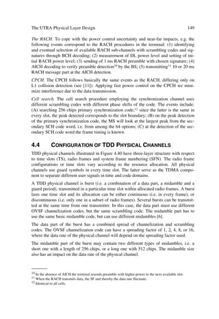
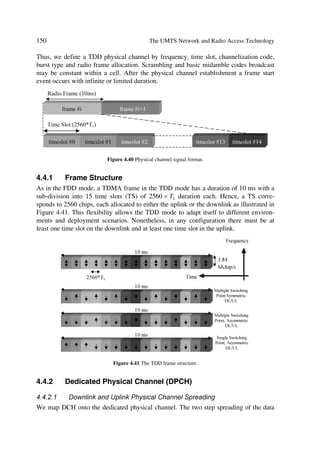
![The UMTS Development Platform 57
integrated network elements as shown in Figure 3.3. In particular, mobility management
and call control bring in new interoperability requirements. These requirements are
summarized next before we concentrate on describing the different UMTS building
blocks of the radio network in forthcoming chapters.
3.2.6.1 Iu Interface Inter-Working Characteristics
The Iu principles presented in [5] apply to PS and CS networks. In this context,
UTRAN supports two logically independent signalling flows via the Iu interface to
combined or separated network nodes of different types like MSC and SGSN [3].
Thus, UTRAN contains domain distribution function routing application independent
UE control signalling to a corresponding CN domain. The UE indicates the addressed
application type through a protocol discriminator for example. Then UTRAN maps this
onto a correct Iu instance to forward signalling. UTRAN services, including radio ac-
cess bearers, are CN domain independent, e.g. we can get speech bearer either through
the PS or CS core network. The Iu includes control and user planes.
Because only a RNC can identify the actual packet volume successfully transferred to a
UE, it indicates the volume of all not transferred downlink data to the 3G-SGSN so this
latter can correct its counter.
3.2.6.1.1 Iu Control Plane
Both PS and circuit CS domains use the Signalling Connection Control Part (SCCP)
protocol to transport Radio Access Network Application Part (RANAP) messages over
the Iu interface. Likewise, both SCCP and RANAP protocols comply with ITU-T rec-
ommendations. In R99, SCCP messages in CS domain use a broadband SS7 stack com-
prising MTP3b on top of SAAL-NNI. In the PS domain UMTS specs allow operators to
chose one out of two standardized protocol suites, i.e. broadband SS7 stack comprising
MTP3b on top of SAAL-NNI or IETF/Sigtran CTP protocol suite for MTP3 users with
adaptation to SCCP. Figure 3.5 illustrates the different RANAP stack options.
5$1$3
63
073E D@UATvt‡…hÃ8UQÃQ…‚‡‚p‚y
T88QHUQȆr…†Ã€‚qˆyr
6$$/11, ,3
Figure 3.5 Stack options in the RANAP protocol.
3.2.6.1.2 Iu User Plane
The user plane towards the IP domain works based on an evolved Gn interface, where
we achieve tunnelling of user data packets over the Iu interface through the user plane
part of GTP over UDP/IP. The tunnelling protocol corresponds to an evolution of the
user plane part of the GTP protocol used in GPRS stacked on top of UDP/IP. When](https://image.slidesharecdn.com/wileytheumtsnetworkandradioaccesstechnologyairinterfacetechniquesforfuturemobile-12712253580361-phpapp02/85/Wiley-The-Umts-Network-And-Radio-Access-Technology-Air-Interface-Techniques-For-Future-Mobile-182-320.jpg)
![58 The UMTS Network and Radio Access Technology
transport data uses ATM PVCs, the Iu IP layer provides Iu network layer services such
as routing, addressing, load sharing and redundancy. This leads to an IP network con-
figured to transfer Iu data units between RNSs and 3G-SGSNs.
We can access common layer 2 resources between UTRAN and the IP domain of a CN
through one or several AAL5/ATM permanent VCs. More than one permanent AAL5/
ATM VCs, for example allows load sharing and redundancy.
The UMTS user data plane in the network consists of two tunnels, i.e. a first
IP/UDP/GTP tunnel between RNC and 3G SGSN on the Iu interface and a second
IP/UDP/GTP tunnel between GGSN and 3G SGSN on the Gn interface.
The double tunnel architecture provides hierarchical mobility, allows direct RNC con-
nection to the IP domain backbone, ensures traffic routing through 3G-SGSN to per-
form appropriate charging and legal interface functions, and it also makes room for fu-
ture exploitation of Iu and Gn interfaces. The protocol stack is shown in Figure 3.6.
,X36
5/ 5/ *738 *738
*738 *738
8'3,3 8'3,3 8'3,3 8'3,3
0$ 0$ /
$$/ $$/
$$/ /
/ / $70 $70 / /
8X ,X *Q *L
8( 516 *6*61 ***61
Figure 3.6 Protocol architecture for the IP domain user plane.
Specifications in [3] outline user data retrieval principles in UMTS and at GSM-UTMS
handover for the PS domain. In the following we cover the Radio Access Domain,
which in part will cover UTMS Mobility Management (UMM) and UMTS call control
to complete the context of interoperability between 2G and 3G systems, i.e. GSM and
UMTS.
3.3 THE ACCESS NETWORK DOMAIN
While the access network domain incorporates elements starting the physical layer and
radio protocols, here we concentrate on the UTRAN as part of the radio access network.
3.3.1 UTRAN Architecture
The UTRAN as illustrated in Figure 3.7, contains Radio Network Subsystems (RNSs)
communicating with the Core Network (CN) through the Iu interface. In turn a RNS
contains a Radio Network Controller (RNC) and one or more Node B5. A Node B con-
_______
5
Throughout this book we use ‘Node B’ as noted by the 3GPP specifications. However, we should know that
a Node B is just a 3G-BTS performing more functions than a 2G BTS in GSM for example.](https://image.slidesharecdn.com/wileytheumtsnetworkandradioaccesstechnologyairinterfacetechniquesforfuturemobile-12712253580361-phpapp02/85/Wiley-The-Umts-Network-And-Radio-Access-Technology-Air-Interface-Techniques-For-Future-Mobile-183-320.jpg)
![60 The UMTS Network and Radio Access Technology
Element Identifiers
PLMN The PLMN-Id is made of Mobile Country Code (MCC) and Mobile
Network Code (MNC): PLMN-Id = MCC + MNC
CN Domain Identifies a CN domain edge node for relocation tasks.
It is made up of the PLMN-Id and of the LAC or RAC of the first
accessed cell in the target RNS. The two CN domain identifiers are:
– CN CS Domain-Id = PLMN-Id + LAC
– CN PS Domain-Id = PLMN-Id + LAC+ RAC
RNC RNC-Id together with the PLMN identifier is used to globally iden-
tify the RNC.
RNC-Id or the RNC-Id together with the PLMN-Id is used as RNC
identifier in UTRAN Iub, Iur and Iu interfaces.
SRNC-Id is the RNC-Id of the Serving RNC.
C-RNC-Id is the RNC-Id of the controlling RNC.
D-RNC-Id is the RNC Id of the Drift RNC.
Global RNC-Id = PLMN-Id + RNC-Id
Service area Used to uniquely identify an area consisting of one or more cells
belonging to the same location area
Such an area is called a service area and can be used for indicating
the location of a UE to the CN.
The Service Area Code (SAC) together with the PLMN-Id and the
LAC will constitute the service area identifier.
SAI = PLMN-Id + LAC + SAC
Cell Used to uniquely identify a cell within an RNS
The Cell-Id together with the identifier of the controlling RNC
(CRNC-Id) constitutes the UTRAN Cell Identity (UC-Id)
UC-Id or C-Id is used to identify a cell in UTRAN Iub, Iur and Iu
interfaces. UC-Id = RNC-Id + C-Id
Local Cell Used to uniquely identify the set of resources within a Node B re-
quired to support a cell (as identified by a C-Id).
Also used for the initial configuration of a Node B when no C-Id is
defined.
UE (Radio Network Used as in UTRAN and in signalling messages between UE and
Temporary Identities UTRAN. They include: Serving RNC RNTI (s-RNTI), Drift RNC
(RNTI) as UE identi- RNTI (d-RNTI), Cell RNTI (c-RNTI), UTRAN RNTI (u-RNTI) See
fiers their use in [6]
Resource identifiers Radio network control plane identifiers,
(see [6]) Transport network control plane identifiers and binding identifier.
3.4.2 System Access Control
Through the system access 3G subscribers connect to the UMTS network to use ser-
vices and/or facilities. Subscriber system access may be initiated from either the mobile
side, e.g. a mobile originated call, or the network side, e.g. a mobile terminated call. In
the following we summarize key system access control functions; specifications in [6]
describe additional details.
3.4.2.1 Admission and Congestion Control
Admission control admits or denies new users, new radio access bearers or new radio
links resulting from network tasks, e.g. handover events. It aims to avoid overload situa-](https://image.slidesharecdn.com/wileytheumtsnetworkandradioaccesstechnologyairinterfacetechniquesforfuturemobile-12712253580361-phpapp02/85/Wiley-The-Umts-Network-And-Radio-Access-Technology-Air-Interface-Techniques-For-Future-Mobile-185-320.jpg)
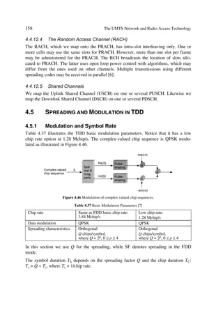
![62 The UMTS Network and Radio Access Technology
3.4.5 Radio Resource Management and Control Functions
Radio resource management concerns the allocation and maintenance of radio commu-
nication resources. In UMTS CS and PS services share these resources.
Not all functions apply to both FDD and TDD modes. For example, macro-diversity
applies only to FDD while dynamic channel allocations applies only to TDD.
3.4.5.1 Radio Resource Configuration
This function configures the radio network resources, i.e. cells and common transport
channels (e.g. BCH, RACH, FACH, PCH), and takes the resources into or out of opera-
tion.
3.4.5.2 Radio Environment Survey
The radio environment survey performs quality estimates and measurements on radio
channels from current and surrounding cells; as in [6] these functions, located in the UE
and UTRANS, include:
œ received signal strengths (current and surrounding cells);
œ estimated bit error ratios, (current and surrounding cells);
œ estimation of propagation environments (e.g. high-speed, low-speed, satellite, etc.);
œ transmission range (e.g. through timing information);
œ Doppler shift;
œ synchronization status;
œ received interference level;
œ total DL transmission power per cell.
3.4.5.3 Macro-diversity Control – FDD
In FDD, macro-diversity control manages duplication/replication of information
streams to receive/transmit the same information through multiple physical channels (or
different cells) from/towards a single mobile terminal.
This function also controls combining of information streams generated by a single
source (diversity link), but conveyed via several parallel physical channels (diversity
sub-links). Macro-diversity control interacts with channel coding control to reduce bit
error ratio when combining different information streams. Depending on the physical
network configuration, combining/splitting may occur at the SRNC, DRNC or Node B
level.
3.4.5.4 TDD – Dynamic Channel Allocation (DCA)
The TDD mode uses fast or slow DCA. Fast DCA implies assigning resources to the
radio bearers in relation to the admission control. Slow DCA implies assigning radio](https://image.slidesharecdn.com/wileytheumtsnetworkandradioaccesstechnologyairinterfacetechniquesforfuturemobile-12712253580361-phpapp02/85/Wiley-The-Umts-Network-And-Radio-Access-Technology-Air-Interface-Techniques-For-Future-Mobile-187-320.jpg)
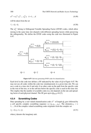
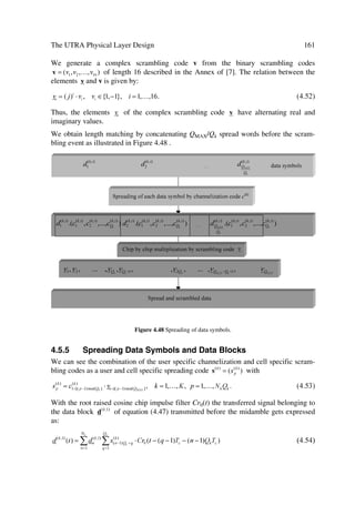
![The UMTS Development Platform 65
3.4.5.11 NAS Core Network Distribution Functions
Non-Access Stratum Messages (NAS) messages in the RRC protocol have transparent
transfer within the access stratum through a direct transfer procedure. A UE/SRNC dis-
tribution function handles a CN domain indicator, service descriptor, and flow ID being
part of the AS message to direct messages to the corresponding NAS entity, i.e. the ap-
propriate mobility management instance in the UE domain and the corresponding CN
domain.
In the downlink the SRNC provides the UE with the necessary information on the origi-
nating CN domain for the individual NAS message.
In the uplink, the UE distribution function inserts the appropriate CN domain values,
domain indicator, service descriptor, and flow ID IEs in the AS message. The SRNC
evaluates the CN domain indicator, service descriptor, and flow ID contained in the AS
message and distributes the NAS message to the corresponding RANAP instance for
transfer over the Iu interface.
3.4.5.12 Timing Advance in TDD
This function aligns uplink radio signals from the UE to the UTRAN. It is based on
uplink burst timing measurements performed by the Node B L1, and on timing advance
commands sent downlink to the UE.
3.4.5.13 NAS Service Specific Function
A UE or SRNC service specific function provides a SAP for particular services (e.g.
priority levels). In the downlink direction, the SRNC may base the routing on this SAP.
3.5 MOBILITY MANAGEMENT
3.5.1 Signalling Connection
The UE may or may not have a signalling connection, and in the radio interface dedi-
cated or common channels can be used [7].
When an established signalling connection exists over the Dedicated Control Service
Access Point (DC-SAP) from the access stratum, the CN reaches the UE by a dedicated
connection SAP on the CN side with a context between UTRAN and UE for the given
connection. This context disappears when the connection is released and a dedicated
connection can be initiated only from the UE.
When a dedicated connection does not exist, the CN reaches the UE through the notifi-
cation SAP, where the CN message may request the UE to establish a dedicated connec-
tion. The UE is addressed with a user/terminal identity and a geographical area.
The location of the UE is known either at cell level (higher activity) or in a larger area
consisting of several cells (lower activity). Knowing the location minimizes the number
of location update messages for moving UEs with low activity and removes paging
needs for UEs with high activity.](https://image.slidesharecdn.com/wileytheumtsnetworkandradioaccesstechnologyairinterfacetechniquesforfuturemobile-12712253580361-phpapp02/85/Wiley-The-Umts-Network-And-Radio-Access-Technology-Air-Interface-Techniques-For-Future-Mobile-190-320.jpg)
![66 The UMTS Network and Radio Access Technology
3.5.2 Impacts of Mobility Handling
In the presence of a dedicated connection to the UE, the UTRAN handles the UE radio
interface mobility, such as soft handover, and procedures for handling mobility in the
RACH/PCH substrate. The radio network cell structure should not necessarily be
known outside the UTRAN.
In the absence of a dedicated connection to the UE, mobility handling occurs directly
between the UE and CN outside the access stratum, e.g. through registration procedures.
While paging the UE, the CN indicates a geographical area which becomes the actual
paged cell in UTRAN. Within a cell structure we may use location area identities or
other means to identify a geographical area independently.
While a dedicated connection lasts, the UE suppresses its registrations to the CN and re-
registers if required. Thus, the UTRAN does not contain any permanent location regis-
ters for the UE, but only temporary contexts for the duration of the dedicated connec-
tion. This context may typically contain location information (e.g. current cell(s) of the
UE) and information about allocated radio resources and related connection references
[6].
3.6 UTRAN SYNCHRONIZATION AND OM REQUIREMENTS
3.6.1 Synchronization Model
The main synchronization issues in UTRAN include: network, node, transport channel,
radio interface, and time alignment synchronization. Figure 3.10 illustrates the nodes
involved in these issues (with exception of network and node synchronization).
9RFRGHU
Uv€rÃ6yvt€r‡
1
Chqyvt
516
51 51
U…h†ƒ‚…‡Ã8uhry
T’pu…‚v“h‡v‚
I‚qrÃ7 1RGH % 1RGH % 1RGH % 1RGH %
875$1
Shqv‚ÃD‡r…shpr
T’pu…‚v“h‡v‚
bU99dÃShqv‚
D‡r…shpr
8( 8(
Pƒ‡v‚hyÃU99Ây’Ãvƒˆ‡
T’p
Ɉ‡ƒˆ‡Ã†’pÂ…‡†
Figure 3.10 Synchronization issues model.](https://image.slidesharecdn.com/wileytheumtsnetworkandradioaccesstechnologyairinterfacetechniquesforfuturemobile-12712253580361-phpapp02/85/Wiley-The-Umts-Network-And-Radio-Access-Technology-Air-Interface-Techniques-For-Future-Mobile-191-320.jpg)
![The UMTS Development Platform 67
3.6.2 Node B OM
Figure 3.11 illustrates the two Node B OM types, i.e. the implementation specific
OM linked to the actual implementation of Node B, and the logical OM having im-
pacts on the traffic carrying resources in Node B controlled from the RNC.
3.6.2.1 Implementation Specific OM
Implementation specific OM functions depend on both HW and SW management
components of Node B, and their transport from Node B to the management system
occurs via the RNC. The implementation specific OM interface shares the same
physical bearer with the Iub interface, where [8] specifies the routing function and the
transport bearer.
Routing across the RNC in the UTRAN is optional, but signalling between co-located
equipment and its management system is required, this may be carried over the same
bearer as the implementation specific OM.
3.6.2.2 Logical OM
The logical OM represents the signalling associated with the control of logical re-
sources owned by the RNC but physically implemented in Node B (e.g. channels, cells,
etc.). The RNC controls these logical resources. A number of OM procedures physi-
cally implemented in Node B impact on the logical resources requiring an information
exchange between RNC and Node B. All messages needed to support this information
exchange are classified as logical OM forming an integral part of NBAP [6].
0DQDJHPHQW 3ODWIRUPV](https://image.slidesharecdn.com/wileytheumtsnetworkandradioaccesstechnologyairinterfacetechniquesforfuturemobile-12712253580361-phpapp02/85/Wiley-The-Umts-Network-And-Radio-Access-Technology-Air-Interface-Techniques-For-Future-Mobile-192-320.jpg)
![I‚qrÃ7 SI8 I‚qrÃ7 8‚y‚ph‡rq
Hhhtr€r‡ Hhhtr€r‡ Hhhtr€r‡ r„ˆvƒ€r‡
H‚qry H‚qry H‚qry Hhhtr€r‡
H‚qry
8‚y‚ph‡rq
r„ˆvƒ€r‡
I‚qrÃ7 I‚qrÃ7
D€ƒyr€r‡h‡v‚ PÉHƃrpvsvp
†ƒrpvsvpÃPÉH SI8ÃPÉH D€ƒyr€r‡h‡v‚
I‚qrÃ7
G‚tvphy G‚tvphy
G‚tvphy
PÉH PÉH
PÉH
DXE DXE
v‡r…shpr v‡r…shpr
U…hssvp
U…hssvp U…hssvp
Aˆp‡v‚†
Aˆp‡v‚† Aˆp‡v‚†
SI8
Figure 3.11 RNS architecture with OM interfaces [6].](https://image.slidesharecdn.com/wileytheumtsnetworkandradioaccesstechnologyairinterfacetechniquesforfuturemobile-12712253580361-phpapp02/85/Wiley-The-Umts-Network-And-Radio-Access-Technology-Air-Interface-Techniques-For-Future-Mobile-193-320.jpg)
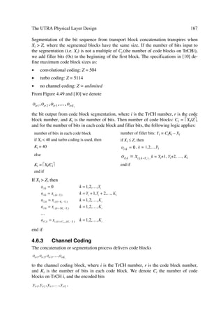
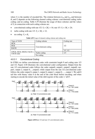
![70 The UMTS Network and Radio Access Technology
transport network control plane during real time operation, but the control actions re-
quired for setting up the signalling bearer(s) for application protocol are considered
OM actions.
The following section is an informative section which aims to provide an overall picture
of how the MAC layer is distributed over Uu, Iub and Iur for the RACH, FACH and
DCH [7].
3.8 RADIO INTERFACE PROTOCOL ARCHITECTURE
This section covers essential aspects on the radio interface protocols based on [9]. For
completeness and to remain close to the technical specifications we use the same termi-
nology and keep the approach of the proposed architecture.
3.8.1 Protocol Structure
Radio interface protocols establish, adapt, and free radio bearer services in the UTRA
platform. They have functions in Layers 1–3, i.e. physical (L1), link (L2) and network
(L3) layers in the OSI terminology. L2 has in turn the following sub-layers: Medium
Access Control (MAC), Radio Link Control (RLC), Packet Data Convergence Protocol
(PDCP) and Broadcast/Multicast Control (BMC). L3 and RLC consist of Control (C)
and User (U) planes. The PCDP and BMC sub-layers exist only in the U plane.
Layer 3 has sub-layers in the C-plane. The lowest one, the Radio Resource Control
(RRC), interfaces with L2 and terminates in the UTRAN. The next sub-layer provides
duplication avoidance functionality [10] and terminates in the CN. It remains part of the
access stratum to provide access stratum services to higher layers. However, we assume
that higher layer signalling such as Mobility Management (MM) and Call Control (CC)
does not belong to the non-access stratum6.
In the architecture representation shown by Figure 3.13, each block indicates an in-
stance of the respective protocol. At the interface between sub-layers, we mark with
ovals Service Access Points (SAP) for peer-to-peer communication. The SAP between
MAC and the physical layer provides the transport channels, and SAPs between RLC
and the MAC sub-layer provide the logical channels. In the C-plane, the General Con-
trol (GC) defines through Notification (Nt) and Dedicated Control (DC) SAPs the inter-
face between duplication avoidance and higher L3 sub-layers (CC, MM).
Figure 3.13 also illustrates connections between RRC and MAC as well as RRC and L1
affording local inter-layer control services. We have as well, an equivalent interface
control between RRC and the RLC sub-layer, between RRC and the PDCP sub-layers
and between RRC and the BMC sub-layer. These interfaces enable the RRC to control
the configuration of the lower layers. Thus, separate control SAPs defined between
RRC and each lower layer (PDCP, RLC, MAC, and L1) exist.
_______
6
Higher level signalling is not in the scope of 3GPP TSG RAN. On the other hand, the UTRA radio interface
protocol architecture has similarities to the current ITU-R protocol architecture, ITU-R M.1035.](https://image.slidesharecdn.com/wileytheumtsnetworkandradioaccesstechnologyairinterfacetechniquesforfuturemobile-12712253580361-phpapp02/85/Wiley-The-Umts-Network-And-Radio-Access-Technology-Air-Interface-Techniques-For-Future-Mobile-201-320.jpg)
![The UMTS Development Platform 71
The RLC sub-layer provides ARQ functionality in conjunction with the applied radio
transmission technique. In this case, we do not see a difference between RLC instances
in C and U planes. When the Iu connection-point remains unchanged, the CN may re-
quest the UTRAN full data protection. However, when the Iu connection point changes
(e.g. SRNS relocation, streamlining, etc.), the UTRAN may not guarantee full data pro-
tection, but rely on duplication avoidance functions in the CN.
8‚‡…‚yÃyhrÆvthyyvt V†r…ÃyhrÃvs‚…€h‡v‚
I‡ 98
B8
9ˆƒyvph‡v‚Ãh‰‚vqhpr
I‡ 98
B8
VˆTÃi‚ˆqh…’
/
p‚‡…‚y
SS8
Q98Q
/3'3
Q98Q
O O O O
R
U R
U R
U R
U
W W W W
Q Q Q Q
R
F R
F R
F R
F
7H8
/%0
/5/
SG8 SG8
SG8
SG8
SG8
SG8
SG8 SG8
G‚tvphy
8uhry†
ÃÃÃH68
/0$
U…h†ƒ‚…‡
8uhry†
QC`
/
Figure 3.13 Radio interface protocol architecture (ovals are service access points) (after [9]).
3.8.1.1 Service Access Points and Service Primitives
At SAPs each layer provides services where a set of primitives or operations defines
every service that a layer provides to the upper layer(s). There exists control services at
Control SAPs (C-SAP) enabling the RRC layer to control lower layers locally (i.e. not
requiring peer-to-peer communication)7. See primitives in [9].
_______
7
C-SAP primitives can bypass one or more sub-layers.](https://image.slidesharecdn.com/wileytheumtsnetworkandradioaccesstechnologyairinterfacetechniquesforfuturemobile-12712253580361-phpapp02/85/Wiley-The-Umts-Network-And-Radio-Access-Technology-Air-Interface-Techniques-For-Future-Mobile-202-320.jpg)
![72 The UMTS Network and Radio Access Technology
3.8.2 Services and Functions in Layer 1
L1 or the physical layer provides information transfer services to MAC and upper lay-
ers. We characterize these services by how and with what features information gets
transferred over the air interface, and we denote them transport channels8’.
3.8.2.1 Services
3.8.2.1.1 Transport channels
In principle we classify transport channels in two groups, i.e. common and dedicated
channels. The 1st group has in-band identification of UEs when addressing particular
UEs. The 2nd group has identification of UEs through the physical channel, i.e. code
and frequency for FDD and code, time slot and frequency for TDD.
Table 3.3 Transport Channel Summary [8]
Transport channels description
Common
Random Access Channel A contention based uplink channel used for transmission of
(RACH) relatively small amounts of data, e.g. for initial access or non-
real-time dedicated control or traffic data.
Common Packet Channel A contention based channel used for transmission of bursty
(CPCH) data traffic. This channel only exists in FDD mode and only
in the uplink direction. The common packet channel is shared
by the UEs in a cell and therefore, it is a common resource.
The CPCH is fast power controlled.
Forward Access Channel Common downlink channel without closed-loop power con-
(FACH) trol used for transmission of relatively small amount of data.
Downlink Shared Channel A downlink channel shared by several UEs carrying dedi-
(DSCH) cated control or traffic data.
Uplink Shared Channel An uplink channel shared by several UEs carrying dedicated
(USCH) control or traffic data, used in TDD mode only.
Broadcast Channel (BCH) A downlink channel used for broadcast of system information
into an entire cell.
Paging Channel (PCH) A downlink channel used for broadcast of control informa-
tion into an entire cell allowing efficient UE sleep mode pro-
cedures. Currently identified information types are paging
and notification. Another use could be UTRAN notification
of change of BCCH information.
Dedicated
Dedicated Channel (DCH) A channel dedicated to one UE used in uplink or downlink
Fast Uplink Signalling Chan- An uplink channel used to allocate dedicated channels in
nel (FAUSCH) conjunction with FACH
Each transport channel, excluding the FAUSCH9, gets an associated transport format
when having a fixed or slow changing rate, or an associated transport format set when
having a fast changing rate. We define the transport format as a combination of encod-
ing, interleaving, bit rate and mapping onto physical channels [11]. We define the trans-
_______
8
They transport signal and traffic information.
9
It only conveys a reservation request.](https://image.slidesharecdn.com/wileytheumtsnetworkandradioaccesstechnologyairinterfacetechniquesforfuturemobile-12712253580361-phpapp02/85/Wiley-The-Umts-Network-And-Radio-Access-Technology-Air-Interface-Techniques-For-Future-Mobile-203-320.jpg)
![The UMTS Development Platform 73
port format set as a group of transport formats. In the context of the latter, e.g. variable
rate DCH has a transport format set, i.e. one transport format for each rate, whereas a
fixed rate DCH has a single transport format [9].
3.8.2.2 L1 Functions
Chapter 4 describes the main functions of L1; here we list a summary from [9] to com-
plete the services and functions introduction.
œ error detection on transport channels and indication to higher layers;
œ FEC encoding/decoding and interleaving/de-interleaving of transport channels;
œ multiplexing of transport channels and de-multiplexing of coded composite trans-
port channels;
œ rate matching;
œ modulation and spreading/demodulation and de-spreading of physical channels;
œ macro-diversity distribution/combining and soft handover execution;
œ mapping of coded composite transport channels on physical channels;
œ power weighting and combining of physical channels;
œ frequency and time (chip, bit, slot, frame) synchronization;
œ measurements and indication to higher layers (e.g. FER, SIR, interference power,
transmit power, etc.);
œ closed-loop or fast power control;
œ RF processing;
œ support of uplink synchronization (TDD only);
œ support of timing advance on uplink channels (TDD only).
3.8.3 Services and Functions in Layer 2
3.8.3.1 Services and Functions in The MAC Sub-layer
Specification in [12] provide the details of the MAC protocol; here we simply summa-
rize the main services and functions.
3.8.3.1.1 Services to upper layers
œ Data transfer Å provides unacknowledged transfer of MAC SDUs between peer
MAC entities without segmentation.
œ Reallocation of radio resources and MAC parameters Å performs on request of
RRC execution of radio resource reallocation and change of MAC parameters. In
TDD mode, in addition, the MAC handles resource allocation autonomously.
œ Reporting of measurements Å reports local measurements, e.g. traffic volume and
quality indication to the RRC.](https://image.slidesharecdn.com/wileytheumtsnetworkandradioaccesstechnologyairinterfacetechniquesforfuturemobile-12712253580361-phpapp02/85/Wiley-The-Umts-Network-And-Radio-Access-Technology-Air-Interface-Techniques-For-Future-Mobile-204-320.jpg)
![The UMTS Development Platform 75
788CÃ Q88CÃ 988CÃ 888CÃ TC88CÃ 8U8CÃ 9U8CÃ
T6QÃ T6QÃ T6QÃ T6QÃÃ T6QÃ T6QÃ
T6QÃ
H68ÃT6Q†Ã U99Ây’Ã
U…h†ƒ‚…‡Ã
8uhry†Ã
%+ 3+ 3+ )$86+ 5$+ )$+ 86+ '6+ '+
A99Ây’à U99Ây’
Figure 3.14 Logical channels mapped onto transport channels, seen from the UE side [9].
ÃÃ 788CÃ Q88CÃ 988CÃ 888CÃ TC88CÃ 8U8CÃ 9U8CÃ
T6QÃ T6QÃ T6QÃ T6QÃ T6QÃ T6QÃ
T6QÃ
U99Ây’Ã
H68ÃT6Q†Ã
U…h†ƒ‚…‡Ã
78CÃ Q8CÃ 8Q8CÃ A6VT8CÃ S68CÃ A68CÃ VT8CÃ 9T8CÃ 98CÃ
8uhry†Ã
A99Ây’à U99Ây’Ã
Figure 3.15 Logical channels mapped onto transport channels, seen from the UTRAN side [9].
3.8.3.2 MAC Functions
The functions of MAC include:
œ Mapping between logical channels and transport channels.
œ Selection of appropriate transport format for each transport channel depending on
instantaneous source rate.
œ Priority handling between data flows of one UE. “Priorities are e.g. given by attrib-
utes of Radio Bearer services and RLC buffer status. The priority handling is
achieved by selecting a Transport Format Combination for which high priority data
is mapped onto L1 with a ‘high bit rate’ Transport Format, at the same time letting
lower priority data be mapped with a ‘low bit rate’ (could be zero bit rate) Trans-
port Format. Transport format selection may also take into account transmit power
indication from Layer 1” [9].](https://image.slidesharecdn.com/wileytheumtsnetworkandradioaccesstechnologyairinterfacetechniquesforfuturemobile-12712253580361-phpapp02/85/Wiley-The-Umts-Network-And-Radio-Access-Technology-Air-Interface-Techniques-For-Future-Mobile-206-320.jpg)
![76 The UMTS Network and Radio Access Technology
œ Priority handling between UEs by means of dynamic scheduling Å aiming for a
dynamic scheduling for efficient spectrum utilization10. The MAC realizes priority
handling on common and shared transport channels.
œ Identification of UEs on common transport channels. When addressing a particular
UE on a common downlink channel, or when a UE uses the RACH, we need in-
band identification of the UE.
œ Multiplexing/de-multiplexing of higher layer PDUs into/from transport blocks de-
livered to/from the physical layer on common transport channels. The MAC sup-
ports multiplexing for common transport channels as complement to the physical
layer.
œ Multiplexing/demultiplexing of higher layer PDUs into/from transport block sets
delivered to/from the physical layer on dedicated transport channels. The MAC al-
lows service multiplexing for dedicated transport channels.
œ Traffic volume monitoring. Based on the MAC’s measurement of traffic volume on
logical channels and reported to RRC, the latter performs transport channel switch-
ing decisions.
œ Dynamic Transport Channel type switching Å switching execution between com-
mon and dedicated transport channels takes place based on a switching decision de-
rived by the RRC.
œ Ciphering. This function prevents unauthorized acquisition of data. Ciphering oc-
curs in the MAC layer for transparent RLC mode.
œ Access Service Class selection for RACH transmission. The RACH resources (i.e.
access slots and preamble signatures for FDD, timeslot and channelization code for
TDD) may be divided between different Access Service Classes (ASC) in order to
provide different priorities of RACH usage. More than one ASC or all ASCs can get
assigned to the same access slot/signature space. Each ASC will also have a set of
back-off parameters associated with it, some or all of which may be broadcasted by
the network. The MAC function applies the appropriate back-off and indicates to the
PHY layer the RACH partition associated with a given MAC PDU transfer [9].
3.8.3.3 RLC Services and Functions
3.8.3.3.1 Services
œ RLC connection establishment/release.
œ Transparent data transfer Å transmits higher layer PDUs without adding any pro-
tocol information, but may include segmentation/re-assembly functionality.
œ Unacknowledged data transfer Å transmits higher layer PDUs without guarantee-
ing delivery to the peer entity. The unacknowledged data transfer mode has the fol-
lowing characteristics:
_______
10
In the TDD we represent transportable data in terms resource units sets.](https://image.slidesharecdn.com/wileytheumtsnetworkandradioaccesstechnologyairinterfacetechniquesforfuturemobile-12712253580361-phpapp02/85/Wiley-The-Umts-Network-And-Radio-Access-Technology-Air-Interface-Techniques-For-Future-Mobile-207-320.jpg)
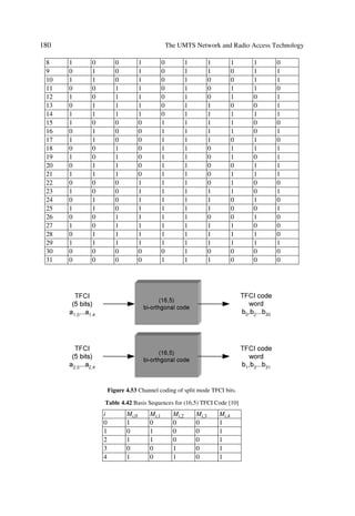
![78 The UMTS Network and Radio Access Technology
œ Duplicate detection. Detects duplicated received RLC PDUs and ensures that the
resultant higher layer PDU get delivered only once to the upper layer.
œ Flow control. Allows an RLC receiver to control the rate at which the peer RLC
transmitting entity may send information.
œ Sequence number check (unacknowledged data transfer mode). Guarantees the
integrity of reassembled PDUs and provides a mechanism for the detection of cor-
rupted RLC SDUs through checking the sequence number in RLC PDUs when they
are reassembled into a RLC SDU.
œ Protocol error detection and recovery. Detects and recovers from errors in the
operation of the RLC protocol.
œ Ciphering. Prevents unauthorized acquisition of data. Ciphering occurs in the RLC
layer for non-transparent RLC mode.
œ Suspend/resume function. Suspension and resumption of data transfer as in e.g.
LAPDm.
3.8.4 PDCP Services and Function
The Packet Data Convergence Protocol (PDCP) service provides transmission and re-
ception of network PDUs in acknowledged/unacknowledged and transparent RLC
mode. As part of its function, first it maps network PDUs from one network protocol to
one RLC entity. Second it compresses in the transmitting entity and decompresses in the
receiving entity redundant network PDU control information (header compression/
decompression), including TCP/IP header compression and decompression when neces-
sary. See more service and function details in [19].
3.8.5 Broadcast/Multicast Control – Services and Functions
The BMC provides broadcast/multicast transmission service in the user plane on the
radio interface for common user data in transparent or unacknowledged mode. Its essen-
tial functions include from [19]:
œ Storage of cell broadcast messages Å stores messages received over the CBC-
RNC interface for scheduled transmission.
œ Traffic volume monitoring and radio resource request for CBS Å at the UTRAN
side, it calculates the required transmission rate for cell broadcast service based on
the messages received over the CBC-RNC interface, and requests appropriate
CTCH/FACH resources from RRC.
œ Scheduling of BMC messages Å The BMC receives scheduling information along
with each cell broadcast message over the CBC-RNC-interface. Based on this
UTRAN scheduling information, it generates schedule messages and schedules
BMC message sequences correspondingly. At the UE side, it evaluates the sched-
uled messages and indicates scheduling parameters to RRC, which are used by the
RRC to configure lower layers for CBS discontinuous reception.](https://image.slidesharecdn.com/wileytheumtsnetworkandradioaccesstechnologyairinterfacetechniquesforfuturemobile-12712253580361-phpapp02/85/Wiley-The-Umts-Network-And-Radio-Access-Technology-Air-Interface-Techniques-For-Future-Mobile-209-320.jpg)
![The UMTS Development Platform 79
œ Transmission of BMC messages to UE Å transmits BMC messages (scheduling
and cell broadcast messages) based on a schedule.
œ Delivery of cell broadcast messages to upper layer (NAS) Å delivers correctly re-
ceived cell broadcast messages to upper layer (NAS) in the UE, neglecting cor-
rupted ones.
Specifications are given in [19], “Data flows through Layer 2”.
3.8.6 Uu Stratum Services and Functions in Layer 3
Here we provide an overview on Layer 3 services and functions based on the Uu Stra-
tum. Further detailed description of the RRC protocol and structured procedures involv-
ing RRC can be found in [20–22].
The main Uu stratum services include: general control, notification and dedicated con-
trol. The first provides a common information broadcast service to all Ues in a certain
geographical area. The second provides paging and notification broadcast services to a
specific UE(s) in a certain geographical area. The third provides services for establish-
ment/release of a connection and transfer of messages using this connection. It should
also be possible to transfer a message during the establishment phase.
3.8.7 The Radio Resource Control (RRC) Functions
The RRC layer handles the control plane signalling of Layer 3 between the UEs and
UTRAN. It main functions include:
œ Broadcast of information provided by the access and non-access stratum (core
network). It performs information broadcasting from the network to all UEs. The
system information is normally repeated on a regular basis.
œ Establishment, re-establishment, maintenance and release of an RRC connection
between the UE and UTRAN. Higher layers request the UE side to establish the first
signalling connection for the UE. The establishment of an RRC connection in-
cludes an optional cell re-selection, an admission control, and a Layer 2 signalling
link establishment.
œ Establishment, reconfiguration and release of radio bearers. Can, on request from
higher layers, perform the establishment, reconfiguration and release of radio bear-
ers in the user plane.
œ Assignment, reconfiguration and release of radio resources for the RRC connec-
tion. It handles the assignment of radio resources (e.g. codes, CPCH channels)
needed for the RRC connection including needs from both the control and user
plane.
œ RRC connection mobility functions. Performs evaluation, decision and execution
related to RRC connection mobility during an established RRC connection, e.g.
handover, inter-system handover preparation, cell re-selection and cell/paging area
update procedures, based on e.g. measurements done by the UE.](https://image.slidesharecdn.com/wileytheumtsnetworkandradioaccesstechnologyairinterfacetechniquesforfuturemobile-12712253580361-phpapp02/85/Wiley-The-Umts-Network-And-Radio-Access-Technology-Air-Interface-Techniques-For-Future-Mobile-210-320.jpg)
![80 The UMTS Network and Radio Access Technology
œ Paging/notification. May broadcast paging information from the network to se-
lected Ues, upon request from higher layers on the network side when necessary, or
can also initiate paging during an established RRC connection.
œ Routing of higher layer PDUs. Performs at the UE side routing of higher layer
PDUs to the correct higher layer entity, at the UTRAN side to the correct RANAP
entity.
œ Control of requested QoS. It ensures that the QoS requested for the radio bearers
can be met, e.g. allocation of a sufficient number of radio resources.
œ UE measurement reporting and control of the reporting. The RRC layer controls
the measurements performed by the UE in terms of what to measure, when to
measure and how to report, including both UMTS air interface and other systems. It
also performs the reporting of the measurements from the UE to the network.
œ Outer loop power control. The RRC layer controls setting of the target of the
closed loop power control.
œ Control of ciphering. Provides procedures for setting of ciphering (on/off) between
the UE and UTRAN.
œ Slow DCA. It applies only to the TDD mode and involves allocating preferred radio
resources dynamically based on long-term decision criteria.
œ Arbitration of radio resources on uplink DCH. Controls rapid radio resource
allocations on uplink DCH using a broadcast channel to send control information to
all involved users.
œ Initial cell selection and re-selection in idle mode. Selection of the appropriate cell
based on idle mode measurements and cell selection criteria.
œ Integrity protection. Adds a Message Authentication Code (MAC-I) to sensitive
and/or containing sensitive information RRC messages.
œ Initial configuration for CBS. Performs the initial configuration of the BMC sub-
layer.
œ Allocation of radio resources for CBS. Allocates radio resources for CBS based on
traffic volume requirements indicated by BMC.
œ Configuration for CBS discontinuous reception. Configures the lower layers (L1,
L2) of the UE when the latter listen to the resources allocated for CBS.
œ Timing advance control. Controls the operation of timing advance, which is appli-
cable only to the TDD mode.
References
[1] 3GPP, Technical Specification Group Services and System Aspects, General UMTS
Architecture (3G TS 23.101. version 3.01, 1999-04).](https://image.slidesharecdn.com/wileytheumtsnetworkandradioaccesstechnologyairinterfacetechniquesforfuturemobile-12712253580361-phpapp02/85/Wiley-The-Umts-Network-And-Radio-Access-Technology-Air-Interface-Techniques-For-Future-Mobile-211-320.jpg)
![The UMTS Development Platform 81
[2] 3GPP, Technical Specification Group Services and System Aspects, Evolution of the GSM
platform towards UMTS (3G TS 23.920. version 3.1, 1999-04).
[3] 3GPP, Architectural Requirements for Release 1999 (3G TS 23.121. version 3.1.0, 1999-
10).
[4] Hentschel, T. and Fettweis, G., “Software Radio Receivers”, in CDMA Techniques for
Third Generation Mobile Systems, Kluwer, Dordrecht, pp. 257–283, 1999.
[5] 3GPP, Technical Specification Group Services and System Aspects, Iu Principles (3G TS
23.930. version 3.0.0, 1999-07).
[6] 3GPP, Technical Specification Radio Access Network Group, UTRAN Overall Description
(3G TS 25.401 version 3.1.0, 2000-01).
[7] UMTS 23.10 UMTS Access Stratum Services and Functions.
[8] TS 25.442: Implementation Specific OM Transport.
[9] 3GPP, Technical Specification Radio Access Network Group, Radio Interface Protocol
Architecture (3G TS 25.301 version 3.4.0, 2000-03).
[10] 3G TS 24.007: Mobile Radio Interface Signalling Layer 3; General Aspects.
[11] 3GPP, Technical Specification Radio Access Network Groupà Services Provided by the
Physical LayerÃ(3G TS 25.302 version 3.4.0, 2000-03).
[12] 3GPP, Technical Specification Radio Access Network Groupà MAC Protocol Specifica-
tionsÃ(3G TS 25.321 version 3.3.0, 2000-03).
[13] 3GPP, Technical Specification Radio Access Network Group, RLC Protocol Specifications
(3G TS 25.322 version 3.2.0, 2000-03).
[14] 3GPP, Technical Specification Radio Access Network Group, PDCP Protocol Specifica-
tions (3G TS 25.323 version 3.1.0, 2000-03).
[15] 3GPP, Technical Specification Radio Access Network Group, BMC Protocol Specification
(3G TS 25.324 version 3.1.0, 2000-03).
[16] 3GPP, Technical Specification Radio Access Network Group, RRC Protocol Specification
(3G TS 25.331 version 3.2.0, 2000-03).
[17] 3GPP, Technical Specification Radio Access Network Group, Physical Layer Procedures
(TDD) (3G TS 25.224 version 3.4.0, 2000-03).
[18] 3G TS 24.007: Mobile Radio Interface Signalling Layer 3; General Aspects.
[19] 3G TS 25.324: BMC Protocol Specification.
[20] 3G TS 25.303: Interlayer Procedures in Connected Mode.
[21] 3G TS 25.304: UE Procedures in Idle Mode and Procedures for Cell Reselection in Con-
nected Mode.
[22] 3G TS 25.331: RRC Protocol Specification.](https://image.slidesharecdn.com/wileytheumtsnetworkandradioaccesstechnologyairinterfacetechniquesforfuturemobile-12712253580361-phpapp02/85/Wiley-The-Umts-Network-And-Radio-Access-Technology-Air-Interface-Techniques-For-Future-Mobile-212-320.jpg)
![82 The UMTS Network and Radio Access Technology
APPENDIX A: UMTS FUNCTIONAL DOMAINS
Figure 3.16 illustrates the four (application, home, serving, and transport) strata. It also
shows the integrated UMTS functional flow, i.e. the interactions between the USIM,
MT/ME, access network, serving network and home network domains, including inter-
actions between TE, MT, access network, serving network, transit network domains and
the remote party.
The direct flows between non-contiguous domains (i.e. non-directly interconnected do-
mains) are transparently transported across all the domains and interfaces located on the
communication path between these end domains. The protocols may or may not be
UMTS specific, as long as they can inter-work seamlessly to facilitate roaming.
When looking at the lower part of Figure 3.16, the home network domain becomes the
transit network domain in the upper part. Thus, the integrated UMTS functional flow
illustrated Figure 3.16, includes the representation or notation of the remote party indi-
cating the remote-end entity (e.g. user or machine). It shows the end-to-end character of
the communication. However, the specification of the remote party is outside the scope
of the UMTS specification [1].
H‚ivyr U…h†v‡
Sr€‚‡r
@„ˆvƒ€r‡ Ir‡ ‚…x
U@ HU
Qh…‡’
9‚€hv D …h†‡…ˆp‡ˆ…rÃ9
s ‚€hv 9‚€hv
6ƒƒyvph‡v‚ÃT‡…h‡ˆ€
C‚€rÃT‡…h‡ˆ€
VTDHÃÃCI
VTDHHU HUÃÃTI TIÃÃCI
Tr…‰vtÃT‡…h‡ˆ€
VTDHÃÃHU HUÃÃTI
U…h†ƒ‚…‡ÃT‡…h‡ˆ€
6ppr† ÃT‡…h‡ˆ€
†
HUÃÃ6I 6IÃÃTI
V H
TD H H
U @ 6ppr†† Tr…‰vt C‚€r
Ir‡ ‚…x Ir‡ ‚…x Ir‡ ‚…x
9‚€hv 9‚€hv 9‚€hv
Figure 3.16 UMTS Architecture functional flow.
Because of the incorporation of the remote party in Figure 3.16, the home (through the
application stratum, the serving and transport strata are extended all the way to the re-
mote party line in the representation. Hence, two GLYHUVLRQ SDWKV UHIOHFW WKH IORZV H[
FKDQJHG EHWZHHQ VHUYLQJ DQG KRPH GRPDLQV RQ RQH VLGH DQG EHWZHHQ VHUYLQJ DQG WUDQ
VLW RQ WKH RWKHU VLGH Starting the first layer the stratum levels are defined in Table 3.6.](https://image.slidesharecdn.com/wileytheumtsnetworkandradioaccesstechnologyairinterfacetechniquesforfuturemobile-12712253580361-phpapp02/85/Wiley-The-Umts-Network-And-Radio-Access-Technology-Air-Interface-Techniques-For-Future-Mobile-213-320.jpg)
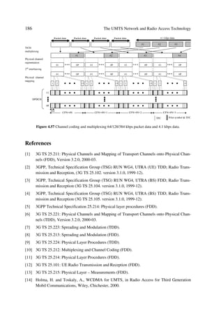
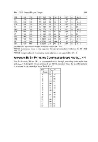
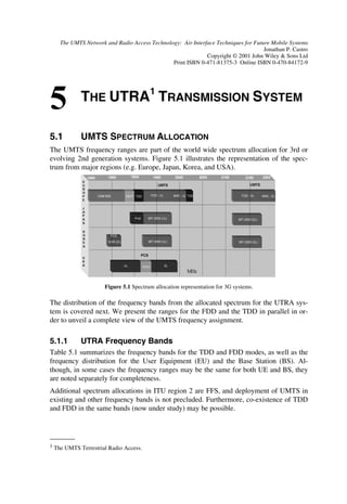
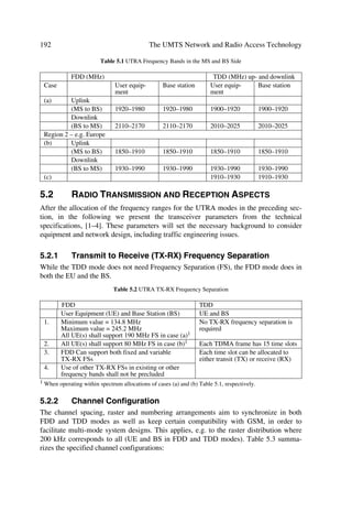
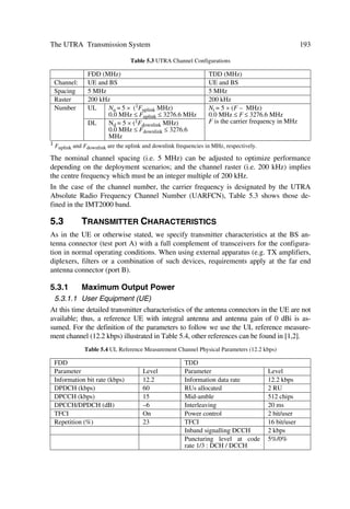
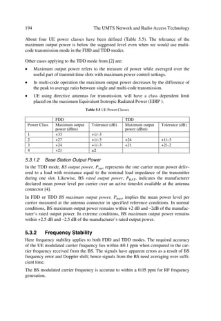
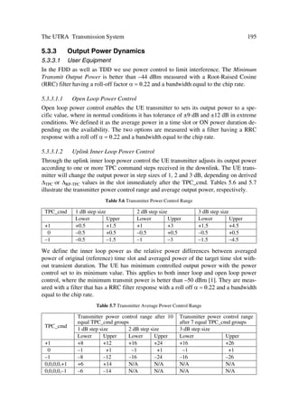
![The UTRA Physical Layer Design 89
CPCH – Common Packet Channel USCH – Uplink Shared Channel
Uplink transport channel associated with a dedi- Uplink transport channel shared by several
cated channel on the downlink, which provides UEs carrying dedicated control or traffic
power control and CPCH control commands data.
(e.g. emergency stop). It is characterized by
initial collision risk and by using inner loop
power control for transmission.
DSCH – Downlink Shared Channel DSCH - Downlink Shared Channel
Downlink transport channel shared by several UEs carrying dedicated control or traffic data. In
FDD it is associated with one or several downlink DCH(s). It may be transmitted over the
entire cell or over only a part of the cell using e.g. beam-forming antennas.
Both FDD and TDD have a similar number of transport channels; however, the FDD
mode does not have an Uplink Shared Channel (USCH) and the TDD mode does not
have a Common Packet Channel (CPCH).
The CPCH transport channel in FDD performs essential power control commands,
which may not be required in TDD. Likewise, the USCH transport channel performs
essential commands in TDD, which may not be required in FDD.
4.3 CONFIGURATION OF FDD PHYSICAL CHANNELS
Physical channels in FDD inherit primarily a layered structure of radio frames and time
slots. A radio frame is a processing unit consisting of 15 slots with a length of 38 400
chips, and slot is a unit consisting of fields containing bits with a length of 2560 chips.
The slot configuration varies depending on the channel bit rate of the physical channel;
thus, the number of bits per slot may be different for different physical channels and
may, in some cases, vary with time. The basic physical resource is the code/frequency
plane, and on the uplink, different information streams may be transmitted on the I and
Q branches. Thus, a physical channel corresponds to a specific carrier frequency, code,
and on the uplink there is in addition a relative phase (0 or p/2) element.
4.3.1 Uplink and Downlink Modulation
The uplink modulation uses a chip rate of 3.84 Mcps, where the complex-valued chip
sequence generated by the spreading process has QPSK modulation as seen in
Figure 4.2. The pulse-shaping characteristics are described in [3].
p‚†w‡
Sr”TXS–
Qˆy†r
Tƒyv‡
Sr”U '/– †uhƒvt
8‚€ƒyr‘‰hyˆrq
TXS …rhyÃÉ
puvƒÃ†r„ˆrpr
v€ht
s…‚€Ã†ƒ…rhqvt U '/
D€”TXS– Qˆy†r
‚ƒr…h‡v‚† ƒh…‡†
D€”U'/– †uhƒvt
†v w‡
Figure 4.2 Uplink/downlink modulation process.](https://image.slidesharecdn.com/wileytheumtsnetworkandradioaccesstechnologyairinterfacetechniquesforfuturemobile-12712253580361-phpapp02/85/Wiley-The-Umts-Network-And-Radio-Access-Technology-Air-Interface-Techniques-For-Future-Mobile-223-320.jpg)
![90 The UMTS Network and Radio Access Technology
The downlink modulation also has a chip rate of 3.84 Mcps, with a QPSK modulated
complex-valued chip sequence generated by the spreading process. Figure 4.2 does also
represent the downlink modulation process. However, the DL pulse-shaping
characteristics are described in [4].
4.3.2 Dedicated Uplink Physical Channels
The two types of uplink dedicated physical channels, i.e. Dedicated Physical Data
Channel (DPDCH) and Dedicated Physical Control Channel (DPCCH) are I/Q code
multiplexed within each radio frame. The uplink DPDCH carries the DCH transport
channel, while the uplink DPCCH carries L1 control information such as: known pilot
bits to support channel estimation for coherent detection, Transmit Power Control
(TPC) commands, Feedback Information (FBI), and an optional Transport Format
Combination Indicator (TFCI).
The TFCI informs the receiver about the instantaneous transport format combination of
the transport channels mapped to the uplink DPDCH transmitted simultaneously. There
is one and only one uplink DPCCH on each radio link; however, there may be zero,
one, or several uplink DPDCHs on each radio link. Figure 4.3 illustrates the frame
structure of the uplink dedicated physical channels, where each frame has 10 ms length
split into 15 slots (Tslot) of 2560 chips length, corresponding to one power control
period.
Parameter k in Figure 4.3 determines the number of bits per uplink DPDCH slot. It is
related to the spreading factor defined as SF = 256/2k, which may range from 256 down
to 4. The SF in the uplink DPCCH is always equal to 256 corresponding to 10 bits per
uplink DPCCH slot. Table 4.4 illustrates the exact number of bits in the uplink DPDCH,
while Table 4.5 shows the different uplink DPCCH fields (i.e. Npilot, NTFCI, NFBI, and
NTPC). The pilot patterns are given Table 4.6 and the TPC bit pattern is given in Table
4.8. Upper layers configure the slot format. The channel symbol rate and SF for all
cases in Table 4.5 are 15 and 256, respectively. Channel bit and symbol rates illustrated
in Tables 4.4 and Table 4.5 reflect rates before spreading.
N
UVORWÃ2Ã!$%Ãpuvƒ†ÃIGDWDÃ2à ! Ãiv‡†Ãx2%
GDWDÃiv‡†
'3'+
9h‡h)ÃI
UVORWÃ2Ã!$%Ãpuvƒ†Ã Ãiv‡†
'3+ Qvy‚‡)ÃISLORWÃiv‡† UA8D)ÃI 7),Ãiv‡† A7D)ÃI )%,Ãiv‡† UQ8)ÃI 73Ãiv‡†
Ty‚‡Ã Ty‚‡Ã Ty‚‡Ã$ Ty‚‡Ã #
Ã…hqv‚Ãs…h€r)ÃUIÃ2à À†
Figure 4.3 Uplink frame structure DPDCH/DPCCH.](https://image.slidesharecdn.com/wileytheumtsnetworkandradioaccesstechnologyairinterfacetechniquesforfuturemobile-12712253580361-phpapp02/85/Wiley-The-Umts-Network-And-Radio-Access-Technology-Air-Interface-Techniques-For-Future-Mobile-224-320.jpg)
![The UTRA Physical Layer Design 91
The FBI bits (S field and D field) support the techniques requiring feedback from the
UE to the UTRAN access point, including closed loop mode transmit diversity and Site
Selection Diversity Transmission’ (SSDT). The open SSDT signalling uses the S field
and the closed loop mode transmit diversity signalling uses the D field. The S field con-
sists of 0, 1 or 2 bits while the D field consists of 0 or 1 bit. Table 4.5 shows the total
FBI field size, i.e. the NFBI. Simultaneous use of SSDT power control and closed loop
mode transmit diversity requires that the S field consists of 1 bit. The use of the FBI
fields is described in detail in [5].
Table 4.4 DPDCH Fields
Slot Channel bit Channel symbol SF Bits/frame Bits/slot Ndata
format #i rate (kbps) rate (ksps)
0 15 15 256 150 10 10
1 30 30 128 300 20 20
2 60 60 64 600 40 40
3 120 120 32 1200 80 80
4 240 240 16 2400 160 160
5 480 480 8 4800 320 320
6 960 960 4 9600 640 640
There are two types of uplink dedicated physical channels; those that include TFCI (e.g.
for several simultaneous services) and those that do not include TFCI (e.g. for fixed-rate
services). These types are reflected by the duplicated rows of Table 4.5. It is the UT-
RAN that determines if a TFCI should be transmitted and it is mandatory for all UEs to
support the use of TFCI in the uplink. The mapping of TFCI bits onto slots is described
in [3]. In compressed mode, DPCCH slot formats with TFCI fields are changed. There
are two possible compressed slot formats for each normal slot format. They are labelled
A and B and the selection between them is dependent on the number of slots that are
transmitted in each frame in compressed mode.
Table 4.5 DPCCH Fields
Slot Channel bit Bits/ Bits/s Npilot NTP NTFCI NFBI Slots/
format #i rate (kbps) frame lot C frame
0 15 150 10 6 2 2 0 15
0A 15 150 10 5 2 3 0 10–14
0B 15 150 10 4 2 4 0 8–9
1 15 150 10 8 2 0 0 8–15
2 15 150 10 5 2 2 1 15
2A 15 150 10 4 2 3 1 10–14
2B 15 150 10 3 2 4 1 8–9
3 15 150 10 7 2 0 1 8–15
4 15 150 10 6 2 0 2 8–15
5 15 150 10 5 1 2 2 15
5A 15 150 10 4 1 3 2 10–14
5B 15 150 10 3 1 4 2 8–9](https://image.slidesharecdn.com/wileytheumtsnetworkandradioaccesstechnologyairinterfacetechniquesforfuturemobile-12712253580361-phpapp02/85/Wiley-The-Umts-Network-And-Radio-Access-Technology-Air-Interface-Techniques-For-Future-Mobile-225-320.jpg)
![92 The UMTS Network and Radio Access Technology
The pilot bit patterns are described in Tables 4.6 and 4.8. The shadowed column part of
pilot bit pattern is defined as FSW, which can be used to confirm frame synchroniza-
tion. (The value of the pilot bit pattern other than FSWs shall be ‘1’.)
Table 4.6 Pilot Bit Patterns for Uplink DPCCH with Npilot = 3, 4, 5 and 6
Slot Npilot = 3 Npilot = 4 Npilot = 5 Npilot = 6
%LW
0 1 1 1 1 1 1 1 1 1 1 1 0 1 1 1 1 1 0
1 0 0 1 1 0 0 1 0 0 1 1 0 1 0 0 1 1 0
2 0 1 1 1 0 1 1 0 1 1 0 1 1 0 1 1 0 1
3 0 0 1 1 0 0 1 0 0 1 0 0 1 0 0 1 0 0
4 1 0 1 1 1 0 1 1 0 1 0 1 1 1 0 1 0 1
5 1 1 1 1 1 1 1 1 1 1 1 0 1 1 1 1 1 0
6 1 1 1 1 1 1 1 1 1 1 0 0 1 1 1 1 0 0
7 1 0 1 1 1 0 1 1 0 1 0 0 1 1 0 1 0 0
8 0 1 1 1 0 1 1 0 1 1 1 0 1 0 1 1 1 0
9 1 1 1 1 1 1 1 1 1 1 1 1 1 1 1 1 1 1
10 0 1 1 1 0 1 1 0 1 1 0 1 1 0 1 1 0 1
11 1 0 1 1 1 0 1 1 0 1 1 1 1 1 0 1 1 1
12 1 0 1 1 1 0 1 1 0 1 0 0 1 1 0 1 0 0
13 0 0 1 1 0 0 1 0 0 1 1 1 1 0 0 1 1 1
14 0 0 1 1 0 0 1 0 0 1 1 1 1 0 0 1 1 1
Table 4.7 presents the relationship between the TPC bit pattern and transmitter power
control command.
Table 4.7 TPC Bit Pattern
TPC bit pattern Transmitter power
NTPC = 1 NTPC = 2 control command
1 11 1
0 00 0
While there is only DPCCH per radio link, several parallel DPDCHs using different
channelization codes [4] can be transmitted for the multi-code operation in the uplink
dedicated physical channels.
Table 4.8 Pilot Bit Patterns for Uplink DPCCH with Npilot = 7 and 8
Slot # Npilot = 7 Npilot = 8
%LW
0 1 1 1 1 1 0 1 1 1 1 1 1 1 1 0
1 1 0 0 1 1 0 1 1 0 1 0 1 1 1 0
2 1 0 1 1 0 1 1 1 0 1 1 1 0 1 1
3 1 0 0 1 0 0 1 1 0 1 0 1 0 1 0
4 1 1 0 1 0 1 1 1 1 1 0 1 0 1 1
5 1 1 1 1 1 0 1 1 1 1 1 1 1 1 0
6 1 1 1 1 0 0 1 1 1 1 1 1 0 1 0
7 1 1 0 1 0 0 1 1 1 1 0 1 0 1 0](https://image.slidesharecdn.com/wileytheumtsnetworkandradioaccesstechnologyairinterfacetechniquesforfuturemobile-12712253580361-phpapp02/85/Wiley-The-Umts-Network-And-Radio-Access-Technology-Air-Interface-Techniques-For-Future-Mobile-226-320.jpg)
![The UTRA Physical Layer Design 93
8 1 0 1 1 1 0 1 1 0 1 1 1 1 1 0
9 1 1 1 1 1 1 1 1 1 1 1 1 1 1 1
10 1 0 1 1 0 1 1 1 0 1 1 1 0 1 1
11 1 1 0 1 1 1 1 1 1 1 0 1 1 1 1
12 1 1 0 1 0 0 1 1 1 1 0 1 0 1 0
13 1 0 0 1 1 1 1 1 0 1 0 1 1 1 1
14 1 0 0 1 1 1 1 1 0 1 0 1 1 1 1
4.3.2.1 Spreading DPCCH/DPDCH
In the uplink spreading principle of DPCCH and DPDCHs real-valued sequences of +1
and –1 represent the binary values ‘0’ and ‘1’, respectively. We spread the DPCCH to
the chip rate by the channelization code cc, and the nth DPDCH (or DPDCHn) to the
chip rate by the channelization code cd,n. As illustrated in Figure 4.4, we can transmit
one DPCCH and up to six parallel DPDCHs simultaneously, i.e. 1 ˆ n ˆ 6 [8].
F b
'3'+
G
G
F b
'3'+
S ,
G G
F b
'3'+
G G
6 '3+Q
,M4
6
F G b
'3'+
G
F b
'3'+
G G
4
'3'+
F G b G
S
M
F b
'3+
F F
Figure 4.4 Spreading for uplink DPCCH and DPDCHs.
After channelization, gain factors bc for DPCCH and bd for all DPDCHs weight the
real-valued spread signals, where at every instant in time, at least one of the values bc
and bd have the amplitude 1.0. Likewise after the weighting, we sum the stream of real-
valued chips on the I- and Q-branches and then treat them as a complex-valued stream
of chips. After we scramble these streams by the complex-valued scrambling code
Sdpch.n, the scrambling code application aligns with the radio frames, i.e. the first scram-
bling chip corresponds to the beginning of a radio frame.](https://image.slidesharecdn.com/wileytheumtsnetworkandradioaccesstechnologyairinterfacetechniquesforfuturemobile-12712253580361-phpapp02/85/Wiley-The-Umts-Network-And-Radio-Access-Technology-Air-Interface-Techniques-For-Future-Mobile-227-320.jpg)
![The UTRA Physical Layer Design 95
4.3.3.1.1 The Random-access Transmission Structure
The random-access transmission uses a slotted ALOHA technique with fast acquisition
indication. The UE can start the random-access transmission at the beginning of a num-
ber of well-defined time intervals, denoted access slots as illustrated in Figure 4.5.
There are 15 access slots per two frames and they are spaced 5120 chips apart. The in-
formation about the type of access slots available for random-access transmission
comes from the upper layers.
Figure 4.6 illustrates the random-access transmission structure, where the transmission
consists of one or several preambles of length 4096 chips and a message of length
10 ms or 20 ms. Each preamble has 256 repetitions of 16 chips signature. Thus, there is
a maximum of 16 available signatures, see [4] for more details.
À†Ã Ã…hqv‚Ãs…h€r
3UHDPEOH 3UHDPEOH 3UHDPEOH 0HVVDJH SDUW
FKLSV 0HVVDJH SDUW
!À†Ã‡‚Ã…hqv‚Ãs…h€r†
Figure 4.6 Structure of the random-access transmission.
4.3.3.1.2 The RACH Message Part
Figure 4.7 illustrates the random-access message part radio frame structure, where the
10 ms message part radio frame is split into 15 slots, each having a length Tslot = 2560
chips. Furthermore, each slot consists of two parts, i.e. a data part to which the RACH
transport channel is mapped and a control part that carries Layer 1 control information;
they are transmitted in parallel.
'DWD
'DWD 1GDWD ELWV
3LORW 7),
1SLORW ELWV 17), ELWV
RQWURO 7VORW FKLSV
N ELWV N](https://image.slidesharecdn.com/wileytheumtsnetworkandradioaccesstechnologyairinterfacetechniquesforfuturemobile-12712253580361-phpapp02/85/Wiley-The-Umts-Network-And-Radio-Access-Technology-Air-Interface-Techniques-For-Future-Mobile-229-320.jpg)
![The UTRA Physical Layer Design 97
4.3.3.2 Physical Common Packet Channel (PCPCH)
The Physical Common Packet Channel (PCPCH) carries the CPCH. The CPCH trans-
mission is based on the Digital Sense Multiple Access – Collision Detection (DSMA-
CD) technique with fast acquisition indication. The UE can start transmission at the
beginning of a number of well-defined time-intervals, relative to the frame boundary of
the received BCH of the current cell. The access slot timing and structure are identical
to those defined for the RACH. Figure 4.8 illustrates the structure of the CPCH access
transmission. The PCPCH access transmission consists of one or several Access Pream-
bles [A-P] of length 4096 chips, one Collision Detection Preamble (CD-P) of length
4096 chips, a DPCCH Power Control Preamble (PC-P) which is either 0 slots or 8 slots
in length, and a message of variable length Nx10 ms.
3M 3M
3 Hr††htrÃQh…‡
3
#(%Ãpuvƒ†
Â…Ã'Æy‚‡† I À†rp
6ppr††ÃQ…rh€iyr Ã8‚‡…‚yÃQh…‡
8‚yyv†v‚Ã9r‡rp‡v‚ 9h‡hÃh…‡
Q…rh€iyr
Figure 4.8 Structure of the CPCH access transmission.
4.3.3.2.1 CPCH Access –Power Control and Detection Preamble Parts
œ Like in the RACH, the access CPCH preamble uses signature sequences, but the
number of sequences can be lower. The scrambling codes may differ from the gold
codes segment used in the RACH or could be the same scrambling code.
œ Table 4.12 defines the DPCCH fields form the CPCH PC-P part. The power control
preamble length parameter takes the values 0 or 8 slots, as set by the higher layers.
When the power control preamble length is set to 8 slots, pilot bit patterns from slot
#0 to slot #7 defined in Table 4.8 shall be used for CPCH PC-P.
Table 4.12 DPCCH Fields for CPCH Power Control Preamble Segment
Slot Chan- Channel SF Bits/ Bits/ Npilot NTPC NTFCI NFBI
format nel bit symb. rate Fram Slot
#i rate (ksps) e
(kbps)
0 15 15 256 150 10 6 2 2 0
1 15 15 256 150 10 8 2 0 0
2 15 15 256 150 10 5 2 2 1
3 15 15 256 150 10 7 2 0 1
4 15 15 256 150 10 6 2 0 2
5 15 15 256 150 10 5 1 2 2](https://image.slidesharecdn.com/wileytheumtsnetworkandradioaccesstechnologyairinterfacetechniquesforfuturemobile-12712253580361-phpapp02/85/Wiley-The-Umts-Network-And-Radio-Access-Technology-Air-Interface-Techniques-For-Future-Mobile-232-320.jpg)
![The UTRA Physical Layer Design 99
value –1. The channelization code cc spreads the control part, while channelization code
cd spreads the data part.
After channelization, gain factor bc for the control part and bd for the data part weight
the real-valued spread signals, where at least every instant in time one of the value bc
and bd have the amplitude 1.0. Table 4.9 illustrates quantization steps of the b-values
quantized into 4 bit words.
Once the weighting takes place, we treat the stream of real-valued chips on the I- and
Q-branches as a complex-valued stream of chips. Then the complex-valued scrambling
code Sr-msg,n scrambles this complex-valued signal. The 10 ms scrambling code applica-
tion aligns with the 10 ms message part radio frames, i.e. the first scrambling chip cor-
responds to the beginning of a message part radio frame [8].
pG b G
QS68CÀr††htr
TUPVJQ
qh‡hÃh…‡
D
DwR
R
6
QS68CÀr††htr
p‚‡…‚yÃh…‡
pF b F
w
Figure 4.10 Spreading of PRACH message part.
4.3.3.3.2 PCPCH
As in the PRACH, the PCPCH preamble part consists of a complex-valued code, and
the PCPCH message part includes data and control parts, Figure 4.11 illustrates its
spreading principle.
pG b G
Q8Q8CÀr††htr
TFPVJQ
qh‡hÃh…‡
D
DwR
R
6
Q8Q8CÀr††htr
p‚‡…‚yÃh…‡
pF b F
w
Figure 4.11 Spreading of PCPCH message part.
In the message part, real-value sequences represent the binary control and data parts, i.e.
the binary value ‘0’ maps to the real value +1, while the binary value ‘1’ maps to the](https://image.slidesharecdn.com/wileytheumtsnetworkandradioaccesstechnologyairinterfacetechniquesforfuturemobile-12712253580361-phpapp02/85/Wiley-The-Umts-Network-And-Radio-Access-Technology-Air-Interface-Techniques-For-Future-Mobile-234-320.jpg)
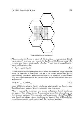
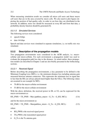
![Figure 4.12 Orthogonal Variable Spreading Factor (OVSF) code-tree generation.
The channelization codes in the OVSF tree have a unique description as Cch,SF,k, where
SF is the spreading factor of the code and k is the code number, 0 ˆ k ˆ SF – 1. Each
level in the code tree defines channelization codes of length SF, corresponding to a
spreading factor of SF. From [8] the generation method for the channelization code is
defined as:
FK
=](https://image.slidesharecdn.com/wileytheumtsnetworkandradioaccesstechnologyairinterfacetechniquesforfuturemobile-12712253580361-phpapp02/85/Wiley-The-Umts-Network-And-Radio-Access-Technology-Air-Interface-Techniques-For-Future-Mobile-242-320.jpg)
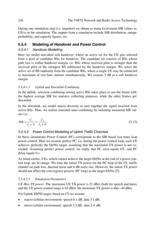
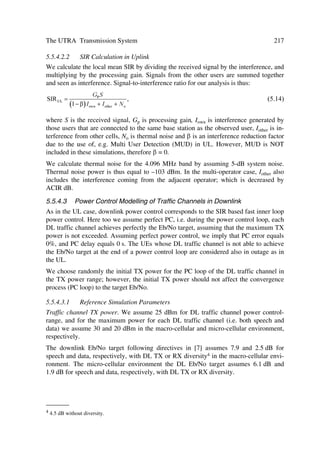
![The UTRA Physical Layer Design 101
The leftmost value in each channelization code word corresponds to the chip transmit-
ted first in time.
4.3.4.1 DPCCH/DPDCH Code Allocation
According to [8] for the DPCCH and DPDCHs the following applies: the DPCCH is
always a code cc = Cch,256,0 as spread; and when we transmit only one DPDCH, the
DPDCH1 has code cd,1 = Cch,SF,k as spread, where SF is the spreading factor of DPDCH1
and k = SF/4. However, when we transmit more than one DPDCH, all DPDCHs have
spreading factors equal to 4. The DPDCHn is spread by the code cd,n = Cch,4,k , where
k = 1 if n ³ {1, 2}, k = 3 if n ³ {3, 4}, and k = 2 if n ³ {5, 6}.
4.3.4.2 PRACH Message Part Code Allocation
The preamble signature s, 0 ˆ s ˆ 15, points to one of the 16 nodes in the code tree that
corresponds to channelization codes of length 16. To spread the message part we use
the sub-tree below a specified node, while to spread the control part we use the chan-
nelization code cc with SF = 256 in the lowest branch of the sub-tree, i.e. cc = Cch,256,m
where m = 16 ™ s + 15. The data part uses any of the channelization codes from spread-
ing factor 32 to 256 in the upper-most branch of the sub-tree. More exactly, we spread
the data part by channelization code cd = Cch,SF,m, SF is the data part spreading factor
and m = SF ™ s/16 [8].
4.3.4.3 PCPCH Message Part Code Allocation
For the control part and data part the following applies: the control part has always code
cc=Cch,256,0 as spread; and the data part has code cd = Cch,SF,k as spread, where SF is the
spreading factor of the data part and k = SF/4. The data part may use the code from
spreading factor 4 to 256, and a UE can increase SF during a message transmission on
frame by frame basis [8].
Finally, the same channelization code of the message control part applies to the PCPCH
power control preamble.
4.3.5 Uplink Scrambling Codes
All uplink physical channels use a complex-valued scrambling code. While either long
or short scrambling codes apply to the DPCCH/DPDCH, to the PRACH and PCPCH
message parts only long scrambling codes apply. Higher layers assign the 224 long and
224 short uplink scrambling codes.
4.3.5.1 Long Scrambling Sequence
The long scrambling sequences clong,1,n and clong,2,n result from the position wise modulo
2 sum of 38 400 chip segments and two binary m sequences generated by means of two
generator polynomials of degree 25. The 1st m sequences, i.e. x comes from the primi-
tive (over GF (2)) polynomial X25 + X3 + 1; while the 2nd m sequences, i.e. y comes
from the polynomial X25 + X3 + X2 + X + 1. The resulting sequences constitute a seg-](https://image.slidesharecdn.com/wileytheumtsnetworkandradioaccesstechnologyairinterfacetechniquesforfuturemobile-12712253580361-phpapp02/85/Wiley-The-Umts-Network-And-Radio-Access-Technology-Air-Interface-Techniques-For-Future-Mobile-246-320.jpg)
![102 The UMTS Network and Radio Access Technology
ment set of gold sequences, where the sequence clong,2,n is a 16 777 232 chip shifted
version of the sequence clong,1,n [8]. Figure 4.13 illustrates a configuration of long uplink
scrambling sequence generator.
For completeness in the following we include an extract of the long scrambling se-
quence definition from [8]. Where n23…n0 = 24 bit binary representation of the scram-
bling sequence number n with n0 as the least significant bit, x sequence which depends
on the chosen scrambling sequence number n is denoted xn, xn(i) and y(i) denote the ith
symbol of the sequence xn and y, respectively. Then m sequences xn and y can be de-
fined as:
[Q](https://image.slidesharecdn.com/wileytheumtsnetworkandradioaccesstechnologyairinterfacetechniquesforfuturemobile-12712253580361-phpapp02/85/Wiley-The-Umts-Network-And-Radio-Access-Technology-Air-Interface-Techniques-For-Future-Mobile-247-320.jpg)
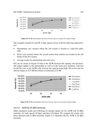
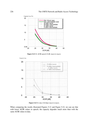
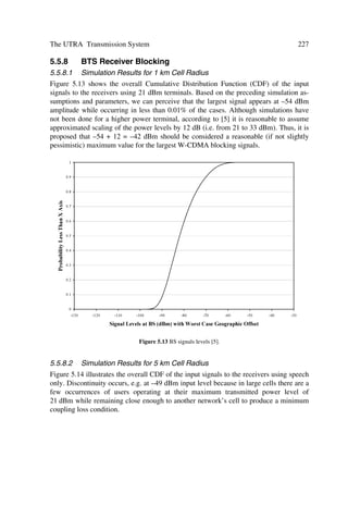
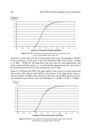
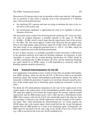
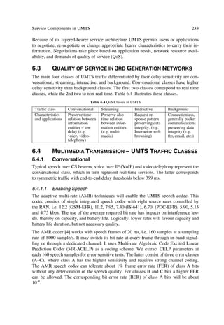
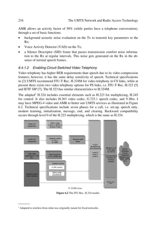
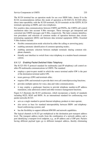
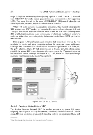
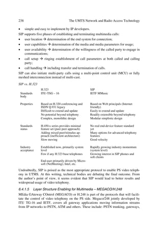
![The binary gold sequence zn can be defined as:
]Q L](https://image.slidesharecdn.com/wileytheumtsnetworkandradioaccesstechnologyairinterfacetechniquesforfuturemobile-12712253580361-phpapp02/85/Wiley-The-Umts-Network-And-Radio-Access-Technology-Air-Interface-Techniques-For-Future-Mobile-268-320.jpg)
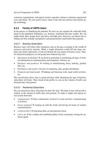
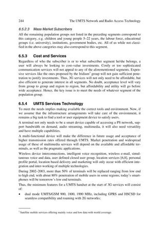
![then the real valued gold sequence Zn is defined by:
Ñ+ LI ]Q L](https://image.slidesharecdn.com/wileytheumtsnetworkandradioaccesstechnologyairinterfacetechniquesforfuturemobile-12712253580361-phpapp02/85/Wiley-The-Umts-Network-And-Radio-Access-Technology-Air-Interface-Techniques-For-Future-Mobile-272-320.jpg)
![Ó - LI ]Q L](https://image.slidesharecdn.com/wileytheumtsnetworkandradioaccesstechnologyairinterfacetechniquesforfuturemobile-12712253580361-phpapp02/85/Wiley-The-Umts-Network-And-Radio-Access-Technology-Air-Interface-Techniques-For-Future-Mobile-275-320.jpg)
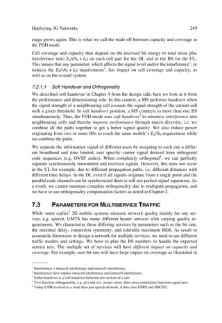
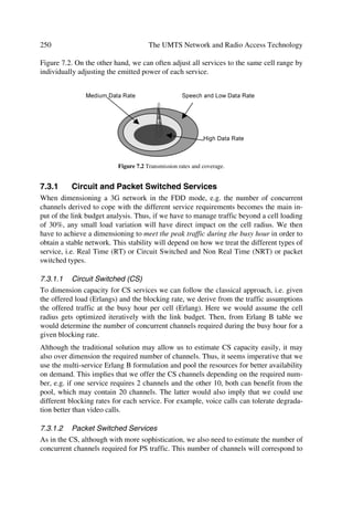
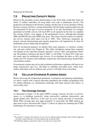
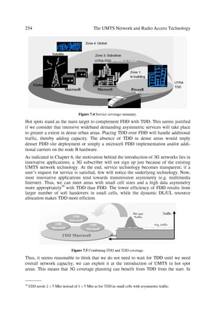
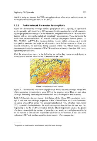
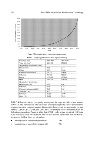
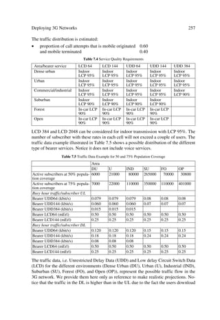
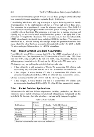
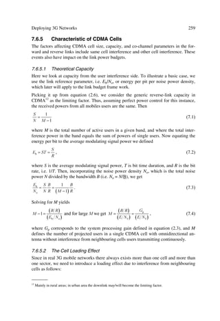
![The UTRA Physical Layer Design 103
/6%
FORQJQ
06%
FORQJQ
Figure 4.13 Configuration of the uplink long scrambling sequence generator.
4.3.5.2 Short Scrambling Sequence
The short scrambling sequences cshort,1,n(i) and cshort,2,n(i) originate from a family se-
quence of periodically extended S(2) codes, where n23n22…n0 = 24 bit binary represen-
tation of the code number n. We obtain the nth quaternary S(2) sequence zn(i), 0 ˆ n ˆ
1677721 by modulo 4 addition of three sequences, a quaternary sequence a(i) and two
binary sequences b(i) and d(i), where the initial loading of the three sequences comes
from the code number n. The sequence zn(i) of length 255 results from the following
relation:
]Q L](https://image.slidesharecdn.com/wileytheumtsnetworkandradioaccesstechnologyairinterfacetechniquesforfuturemobile-12712253580361-phpapp02/85/Wiley-The-Umts-Network-And-Radio-Access-Technology-Air-Interface-Techniques-For-Future-Mobile-288-320.jpg)
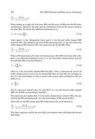
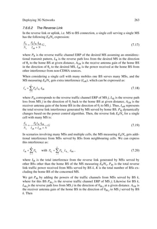
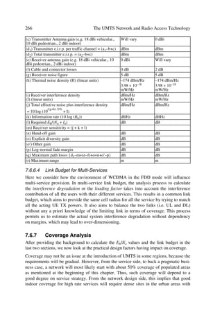
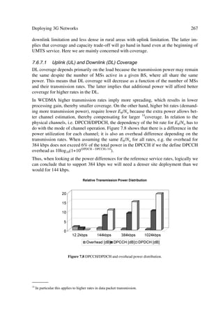
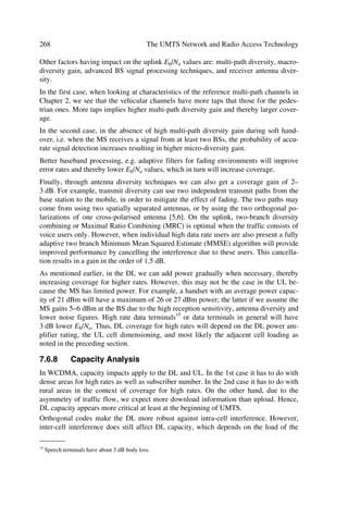
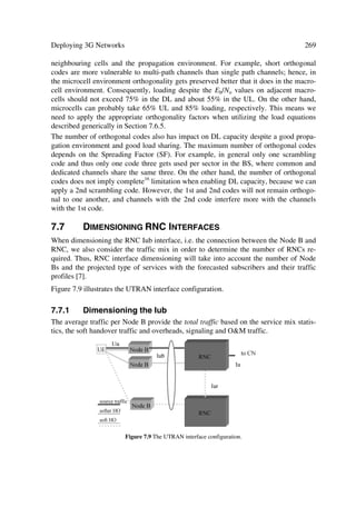
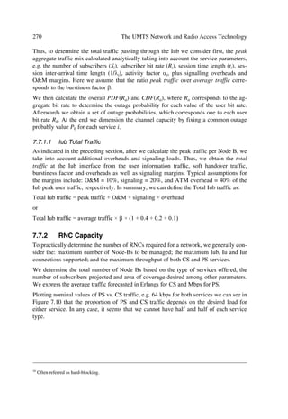
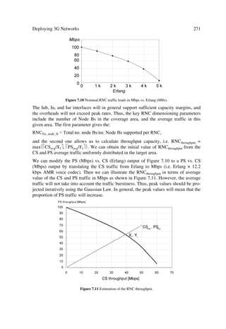
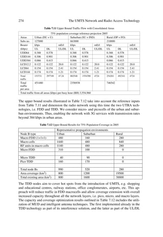
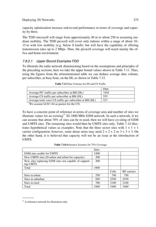
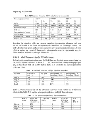
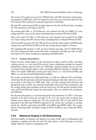
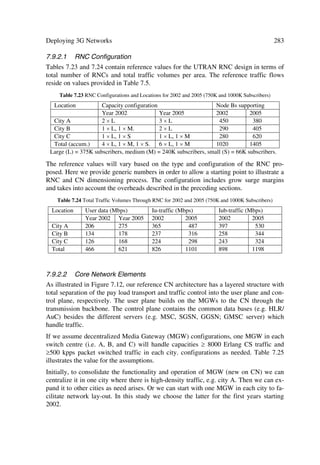
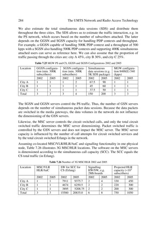
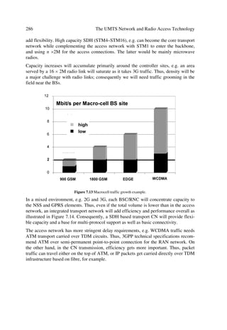
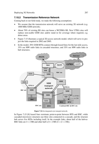
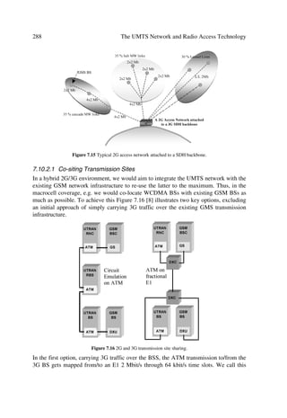
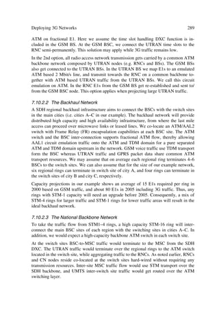
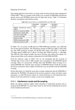
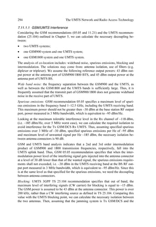
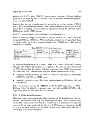
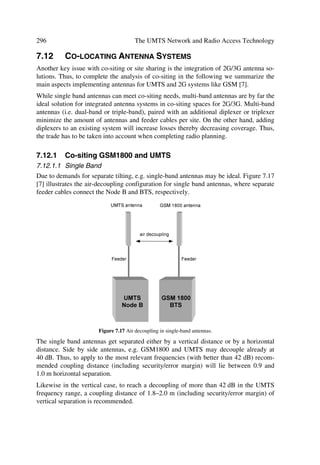
![The UTRA Physical Layer Design 105
From [8], when using long scrambling codes we define the nth uplink DPCCH/DPDCH
scrambling code denoted Sdpch,n, as
6 GSFK Q L](https://image.slidesharecdn.com/wileytheumtsnetworkandradioaccesstechnologyairinterfacetechniquesforfuturemobile-12712253580361-phpapp02/85/Wiley-The-Umts-Network-And-Radio-Access-Technology-Air-Interface-Techniques-For-Future-Mobile-325-320.jpg)
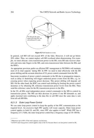
![where the lowest index corresponds to the chip transmitted first in time and Section
4.3.5.2 defines Cshort,n.
4.3.5.4 PRACH and PCPCH Message Part Scrambling Code
The PRACH message part uses 10 ms long scrambling code, and there are 8192 possi-
ble PRACH scrambling codes. From [8] we define the nth PRACH message part
scrambling code, denoted Sr-msg,n, where n = 0,1,…,8191, based on the long scrambling
sequence as
6 UPVJ Q L](https://image.slidesharecdn.com/wileytheumtsnetworkandradioaccesstechnologyairinterfacetechniquesforfuturemobile-12712253580361-phpapp02/85/Wiley-The-Umts-Network-And-Radio-Access-Technology-Air-Interface-Techniques-For-Future-Mobile-331-320.jpg)
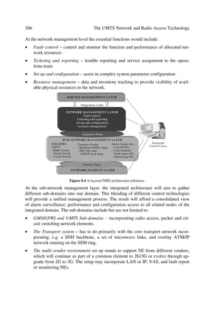
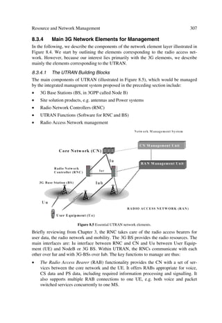
![where the lowest index corresponds to the chip transmitted first in time and Section
4.3.5.1 defines Clong,n.
The message part scrambling code has a one-to-one correspondence to the scrambling
code utilized in the preamble part. For one PRACH, we use the same code number in
both scrambling codes, i.e. if the PRACH preamble scrambling code uses Sr-pre,m then
the PRACH message part scrambling code uses Sr-msg,m, where the number m is the
same for both codes [8].
As in PRACH, PCPCH uses 10 ms long scrambling codes in the message part. They are
cell-specific and each scrambling code has a one-to-one correspondence to the signature
sequence and the access sub-channel utilized by the access preamble part. Both long
and short scrambling codes may scramble the PCPCH message part. We define up to 64
uplink-scrambling codes per cell and up to 32768 different PCPCH scrambling codes in
the system. For the long scrambling sequence we define the nth PCPCH message part
scrambling code (Sc-msg,,n, n = 8192,8193,…,40959) as:
6 FPVJ Q L](https://image.slidesharecdn.com/wileytheumtsnetworkandradioaccesstechnologyairinterfacetechniquesforfuturemobile-12712253580361-phpapp02/85/Wiley-The-Umts-Network-And-Radio-Access-Technology-Air-Interface-Techniques-For-Future-Mobile-334-320.jpg)
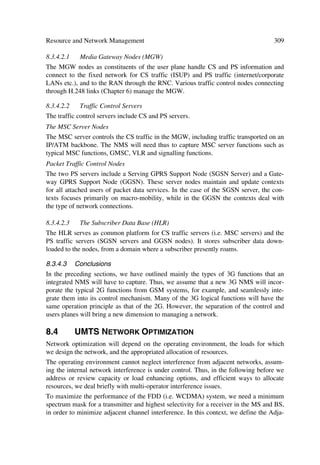
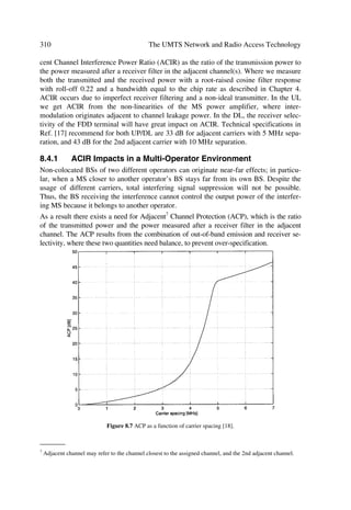
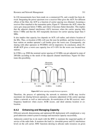
![106 The UMTS Network and Radio Access Technology
scrambling code used in the downlink of the cell match one-to-one. Sc-msg,n as defined in
the preceding paragraphs with n = 64 ™ m + k + 8176, is the kth PCPCH scrambling
code within the cell with downlink primary scrambling code m, where k =16,17,…,79
and m = 0,1,2,…,511 [8].
4.3.5.5 Scrambling Code in the PCPCH Power Control Preamble
The PCPCH power control preamble uses the same scrambling code as the PCPCH
message part (Section 4.3.2.1), where the phase of the scrambling code is such that the
end of the code aligns with the frame boundary at the end of the power control pream-
ble.
4.3.5.6 PRACH Preamble Codes
Complex valued sequence constitutes the random access preamble code Cpre,n,. It origi-
nates from a preamble scrambling code Sr-pre,n and a preamble signature Csig,s as:
Î Ë p p ÛÞ
Q V N](https://image.slidesharecdn.com/wileytheumtsnetworkandradioaccesstechnologyairinterfacetechniquesforfuturemobile-12712253580361-phpapp02/85/Wiley-The-Umts-Network-And-Radio-Access-Technology-Air-Interface-Techniques-For-Future-Mobile-341-320.jpg)
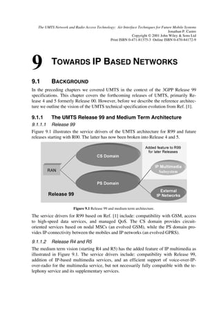
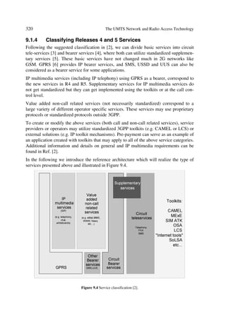
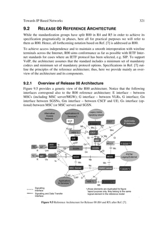
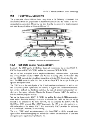
![Ã
where Section 4.3.5.1 defines the sequence clong,1,n.
As for the PCPCH, we divide the 8192 PRACH preamble scrambling codes in 512
groups with 16 codes in each. And again as in the earlier scrambling codes, we have
one-to-one correspondence between the group of PRACH preamble scrambling codes in
a cell and the primary scrambling code used in the downlink of the cell. Sr-pre,n(i) as de-
fined in equation (4.28) with n = 16 ™ m + k, represents the kth PRACH preamble
scrambling code within the cell with downlink primary scrambling code m, k = 0,1,2,…,
15 and m = 0,1,2,…,511.
The preamble signature s has 256 repetitions of the signature Ps(n) from the set of 16
Hadamard codes of length 16 (Table 4.14), where n = 0,…,15. The specifications in [8]
define it as:
VLJ V
L](https://image.slidesharecdn.com/wileytheumtsnetworkandradioaccesstechnologyairinterfacetechniquesforfuturemobile-12712253580361-phpapp02/85/Wiley-The-Umts-Network-And-Radio-Access-Technology-Air-Interface-Techniques-For-Future-Mobile-348-320.jpg)
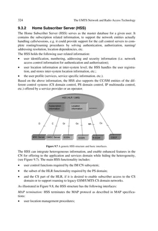
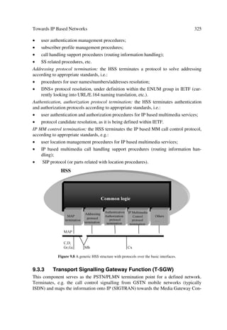
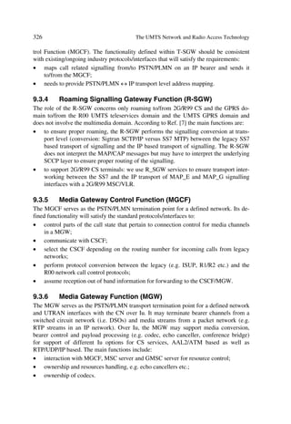
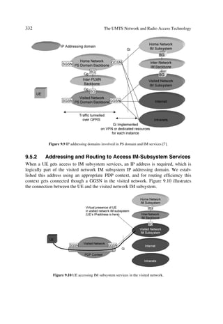
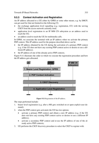
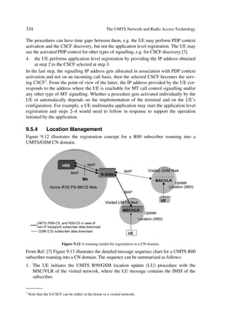
![108 The UMTS Network and Radio Access Technology
When PCPCH and PRACH share scrambling code resources and the index k is less than
16, the corresponding PRACH formulae apply. Otherwise, if the index k is greater than
or equal to 16, the formula in this section applies. The CPCH-access burst preamble part
carries one of the 16 different orthogonal complex signatures identical to the ones used
by the preamble part of the random-access burst [8].
4.3.5.7.1 Collision Detection(CD) Preamble
As in PRACH, the PCPCH CD preamble codes Cc-cd,n,s have complex valued sequences.
We define these preamble codes from the preamble scrambling codes Sc-cd,n and a pre-
amble signature Csig,s as:
Î Ë p p ÛÞ
QV N](https://image.slidesharecdn.com/wileytheumtsnetworkandradioaccesstechnologyairinterfacetechniquesforfuturemobile-12712253580361-phpapp02/85/Wiley-The-Umts-Network-And-Radio-Access-Technology-Air-Interface-Techniques-For-Future-Mobile-360-320.jpg)
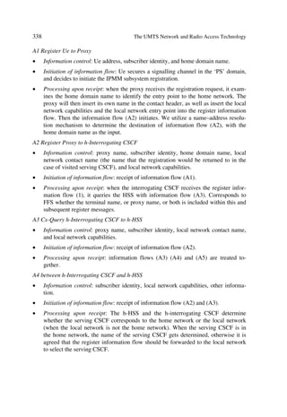
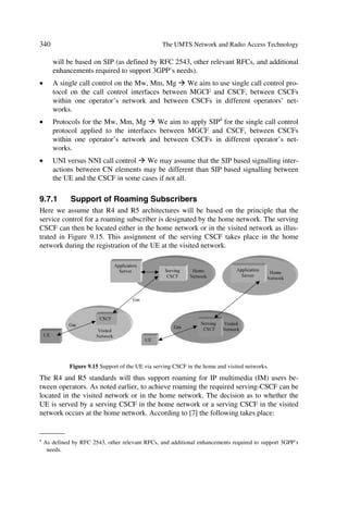
![Ã
where Section 4.3.5.1 defines the sequence clong,1,n.
When RACH and CPCH share scrambling code resources, RACH preamble scrambling
codes will also apply to the CPCH CD preamble. As in the cases above, we divide the
32768 PCPCH scrambling codes into 512 groups with 64 codes each. There exists also
a one-to-one correspondence between the group of PCPCH CD preamble scrambling
codes in a cell and the primary scrambling code used in the downlink of the cell. The
kth PCPCH scrambling code within the cell with downlink primary scrambling code m,
k = 16,17,…,79 and m = 0,1,2,…,511, corresponds to Sc-cd, n as defined in equation
(4.33) with n = 64 ™ m + k + 8176.
When PCPCH and PRACH share scrambling code resources, and the index k is less
than 16 the corresponding PRACH formula applies. Otherwise, when the index k is
greater than or equal to 16, the preceding formulae apply. The CD preamble part of the
CPCH access burst carries one of 16 different orthogonal complex signatures identical
to the ones utilized by the preamble part of the random access burst [8].
4.3.6 Uplink Power Control Procedure
The FDD mode has unique procedures compared to the TDD. These include fast power
control and soft handover procedures. Other procedures are synchronization and ran-
dom access.](https://image.slidesharecdn.com/wileytheumtsnetworkandradioaccesstechnologyairinterfacetechniquesforfuturemobile-12712253580361-phpapp02/85/Wiley-The-Umts-Network-And-Radio-Access-Technology-Air-Interface-Techniques-For-Future-Mobile-367-320.jpg)
![The UTRA Physical Layer Design 109
4.3.6.1 PRACH and DPCCH/DPDCH Power Control
The uplink PRACH message part applies gain factors to manage the control/data part
relative power similar to the uplink dedicated physical channels. Thus, power control
steps in the dedicated physical channels apply also to the RACH message part, with the
differences that [11]:
œ bc is the gain factor for the control part (similar to DPCCH);
œ bd is the gain factor for the data part (similar to DPDCH);
œ no inner or fast loop power control is performed, but open loop power control.
Before the uplink power control procedure simultaneously controls the power of a
DPCCH and its corresponding DPDCHs when present, high layers set the initial uplink
DPCCH transmit power. The network determines this relative transmit power offset
between DPCCH and DPDCHs using the gain factors signalled to the UE. The inner or
fast power control loop operation adjusts the power of the DPCCH and DPDCHs in
steps of 1 dB or multiples of one and smaller steps through emulation at 1500 Hz com-
mand rate. The DPCCH uplink transmit power takes place immediately before the start
of its pilot field. This change occurs with respect to its previous value derived by the
UE, i.e. DDPCCH (in dB). The previous DPCCH power value corresponds to the one used
in the previous slot, except in the event of an interruption in transmission due to the use
of compressed mode. In the latter case, the previous value corresponds to the one used
in the last slot before the transmission gap. While in power control, the UE transmit
power will not exceed a maximum allowed value, i.e. the lowest out of the terminal
maximum output power and the one set by higher layer signalling. If the UE transmit
power falls below the required minimum output power and the derived value of DDPCCH
0, the UE may reduce the DDPCCH magnitude [11].
4.3.6.1.1 The transmit power control function
The uplink inner-loop power control adjusts the UE transmit power to keep the received
uplink signal-to-interference ratio (SIR) at a given target, i.e. SIRtarget. The serving cells
in the active set estimate signal-to-interference ratio (SIRest) of the received uplink
DPCH. Then they generate TPC commands and transmit them once per slot according
to the following rules: if SIRest SIRtarget then the TPC command enables transmission
of ‘0’, otherwise if SIRest SIRtarget then the TPC command enables transmission of ‘1’.
Upon receipt of one or more TPC commands in a slot, the UE derives a single TPC
command, TPC_cmd, for each slot, i.e. it combines multiple TPC commands if more
than one is received in a slot. The UTRAN uses two algorithms supported by the UE2 to
realize a TPC_cmd.
Algorithm 1
1. UE not in soft handover, “ each slots receives only one TPC command, then:
œ If the received TPC_cmd = 0 then TPC_cmd for that slot = –1.
_______
2 The step size D
TPC is a UE specific parameter, under UTRAN control , which can have values 1 dB or 2 dB.](https://image.slidesharecdn.com/wileytheumtsnetworkandradioaccesstechnologyairinterfacetechniquesforfuturemobile-12712253580361-phpapp02/85/Wiley-The-Umts-Network-And-Radio-Access-Technology-Air-Interface-Techniques-For-Future-Mobile-368-320.jpg)
![110 The UMTS Network and Radio Access Technology
œ If the received TPC_cmd = 1, then TPC_cmd for that slot = 1.
2. UE is in soft handover, “ each slot may receive multiple TPC commands from
different cells in the active set. In receiver diversity (i.e. softer handover), the
UTRAN transmits the same command in all the serving cells the UE is in softer
handover with, and the TPC commands known to be the same get combined into
one TPC command (see more details in [11]).
Algorithm 23
1. UE is not in soft handover, “ each slot receives only one TPC command and the
UE processes received TPC commands on a 5-slot cycle. The non-overlapping sets
of 5 slots align to the frame boundaries. The TPC_cmd logic is a follows:
œ The first 4 slots of a set have TPC_cmd = 0.
œ In the fifth slot of a set, the UE uses hard decisions on each of the 5 re-
ceived TPC commands as follows [11]:
œ If all 5 hard decisions within a set are 1 then TPC_cmd = 1 in the
5th slot.
œ If all 5 hard decisions within a set are 0 then TPC_cmd = -1 in the
5th slot.
œ Otherwise, TPC_cmd = 0 in the 5th slot.
2. UE is in soft handover, “ each slot receives multiple TPC commands from differ-
ent cells in the active set. UE is in soft handover, “ each slot may receive multiple
TPC commands from different cells in the active set. In receiver diversity (i.e.
softer handover), the UTRAN transmits the same command in all the serving cells
the UE is in softer handover with, and the TPC commands known to be the same
get combined into one TPC command (see more details in [11]).
After deriving the combined TPC command TPC_cmd using one of the two supported
algorithms, the UE adjusts the transmit power of the uplink DPCCH with a step of
DDPCCH (in dB), which is given by DDPCCH = DTPC ™ TPC_cmd.
Out of sync handling
The UE shuts its transmitter off when the UE estimates the DPCCH quality over the last
200 ms period to be worse than a threshold Qout. This criterion never occurs during the
first 200 ms of the dedicated channel’s existence. The UE can turn its transmitter on
when the UE estimates the DPCCH quality over the last 200 ms period to be better than
a threshold Qin. This criterion always occurs during the first 200 ms of the dedicated
channel’s existence. At the transmission resumption the power of the DPCCH shall re-
main the same as when the UE transmitter went off [12].
_______
3 Allows emulation of smaller step sizes than the minimum power control step or to turn off uplink power
control.](https://image.slidesharecdn.com/wileytheumtsnetworkandradioaccesstechnologyairinterfacetechniquesforfuturemobile-12712253580361-phpapp02/85/Wiley-The-Umts-Network-And-Radio-Access-Technology-Air-Interface-Techniques-For-Future-Mobile-369-320.jpg)
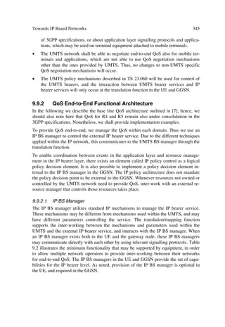
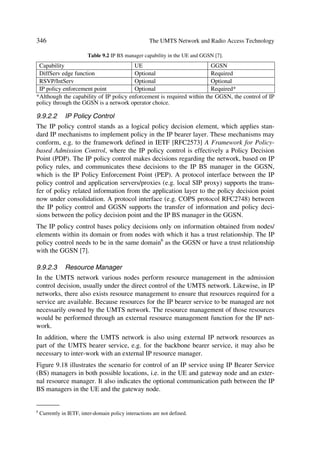
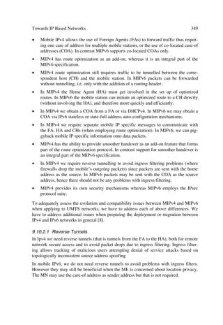
![112 The UMTS Network and Radio Access Technology
transmission, and in the first slot of a downlink transmission gap if a downlink TPC
command is transmitted in that slot. TPC_cmdi is the most recent power control com-
mand derived by the UE [11].
After a transmission gap in either the uplink or the downlink, there exists a recovery
period following resumption of simultaneous uplink and downlink DPCCH transmis-
sion. This period has a Recovery Period Length (RPL) and is expressed as a number of
slots. The RPL is equal to the minimum value out of the transmission gap length and 7
slots. Table 4.15 illustrates the two recovery period modes for the power control algo-
rithm, where the Recovery Period Power (RPP) control mode is signalled with the other
compressed mode parameters [13]. For RPP mode 0, the step size does not change dur-
ing the recovery period and ordinary transmit power control applies, i.e. the algorithm
for processing TPC commands determined by the value of PCA. For RPP mode 1, dur-
ing RPL slots after each transmission gap, power control algorithm 1 applies with a step
size DRP-TPC instead of DTPC, regardless of the value of PCA. We define the uplink
DPCCH transmit power change, which does not apply to the first slot after the transmis-
sion gap, as:
D '3+
=D 5373
™ 73BFPG + D 3,/27](https://image.slidesharecdn.com/wileytheumtsnetworkandradioaccesstechnologyairinterfacetechniquesforfuturemobile-12712253580361-phpapp02/85/Wiley-The-Umts-Network-And-Radio-Access-Technology-Air-Interface-Techniques-For-Future-Mobile-375-320.jpg)
![where DRP-TPC denotes the recovery power control step size and is expressed in dB.
When the PCA has the value 1,¡,DRP-TPC, it is equal to the minimum value of 3 dB and
2DTPC, and when the PCA has the value 2, DRP-TPC, it is equal to 1 dB. After the recov-
ery period, normal transmit power control function resumes using the algorithm speci-
fied by the value of PCA and with step size DTPC. When the PCA has 2 as value, slot
sets over which the TPC commands are processed remain aligned to the frame bounda-
ries in the compressed frame. For both RPP mode 0 and RPP mode 1, if the transmis-
sion gap or the recovery period results in any incomplete sets of TPC commands,
TPC_cmd = zero for those incomplete slots sets [11].
Table 4.15 Initial Transmit Power (ITP) and Recovery Period Power (RPP) Control Modes
ITP DESCRIPTION
0 DRESUME = DTPC ™ TPC_cmdgap
1 DRESUME = dlast
RPP
0 Transmit power control applies using the algorithm deter-
mined by the value of PCA with step size DTPC
1 Transmit power control applies using algorithm 1 with step
size DRP-TPC during RPL slots after each transmission gap
4.3.6.3 DPCCH Power Control Preamble
DCHs can use power control preamble for initialization, and both UL and DL DPCCHs
get transmitted during the uplink power control preamble. However, the UL DPDCH
does not start before the end of the power control preamble. The network signals the
power control preamble length as a UE-specific parameter, where values can take
0 slots or 8 slots. When the preamble length zero, power control details used during](https://image.slidesharecdn.com/wileytheumtsnetworkandradioaccesstechnologyairinterfacetechniquesforfuturemobile-12712253580361-phpapp02/85/Wiley-The-Umts-Network-And-Radio-Access-Technology-Air-Interface-Techniques-For-Future-Mobile-376-320.jpg)
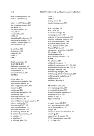
![When PCA = 1, then DTPC-init is equal to the minimum value out of 3 dB and 2DTPC; and
when PCA = 2, then DTPC-init = 2dB. TPC_cmd is derived according to algorithm 1 re-
gardless of the value of PCA. Normal transmit power control with the power control
algorithm determined by the value of PCA and step size DTPC, applies as soon as the
sign of TPC_cmd reverses for the first time, or at the end of the power control preamble
if the power control preamble ends first. The specifications in [11] describe the setting
of the uplink DPCCH/DPDCH power difference.
4.3.6.4 Power Control in the PCPCH Message Part and Preamble
Message part. The uplink inner or fast loop power control adjusts the UE transmit
power to keep the received uplink signal-to-interference ratio (SIR) at a given
SIRTARGET set by upper layer outer loop.
The network estimates the SIREST of the received PCPCH, then it generates TPC com-
mands and transmits the commands once per slot according to the following rule:
œ if SIREST SIRTARGET then the TPC command to transmit = ‘0’, or
œ if SIRest SIRtarget then the TPC command to transmit = ‘1’.
The UE derives a TPC_cmd for each slot. The UE will support the UTRAN controlled
algorithms 1 and 2 to derive a TPC_cmd. These come in step size DTPC and can have
values of 1 dB or 2 dB. After deriving the TPC command TPC_cmd using one of the
two supported algorithms, the UE adjusts the transmit power of the uplink PCPCH in
steps of DTPC dB according to the TPC command. If TPC_cmd = 1, then the transmit
power of the uplink PCPCH increases by DTPC dB. If TPC_cmd = –1, then the transmit
power of the uplink PCPCH decreases by DTPC dB. If TPC_cmd = 0, then the transmit
power of the uplink PCPCH remains unchanged. Any power increase or decrease takes
place immediately before the start of the pilot field on the PCPCH control channel [11].
4.3.6.5 Power Control in the Power Control Preamble Part
The UE begins the power control preamble using the same power level applied for the
CD preamble. The initial power control step size utilized in the power control preamble
differs from the one applied in the message part as follows:
œ When inner loop power control algorithm 1 applies to the message part, then the
initial step size in the power control preamble = DTPC-init, where DTPC-init is the
minimum value out of 3 dB and 2DTPC, where DTPC is the power control step size
used for the message part.](https://image.slidesharecdn.com/wileytheumtsnetworkandradioaccesstechnologyairinterfacetechniquesforfuturemobile-12712253580361-phpapp02/85/Wiley-The-Umts-Network-And-Radio-Access-Technology-Air-Interface-Techniques-For-Future-Mobile-378-320.jpg)
![114 The UMTS Network and Radio Access Technology
œ When inner loop power control algorithm 2 applies to the message part, then we
use initially the inner loop power control algorithm 1 in the power control pream-
ble, with a step size of 2dB.
œ In either one of the cases, the power control algorithm and step size revert to ones
used for the message part as soon as the sign of the TPC commands reverses for the
first time [11].
4.3.7 Downlink Physical Channels
4.3.7.1 Downlink Transmit Diversity
Table 4.16 outlines possible applications of open and closed loop transmit diversity
modes on different types of downlink physical channel. Simultaneous use of STTD and
closed loop modes on the same physical channel is not possible. Furthermore, when Tx
diversity applies to any of the downlink physical channels, it also apply to the
P-CCPCH and SCH.
In addition, the PDSCH and the DPCH associated with this PDSCH shall use the same
transmit diversity mode. A transmit diversity mode (open loop or closed loop) on the
associated DPCH may not change while the duration of the PDSCH frame, and within
the slot prior to the PDSCH frame. Nevertheless, changing from closed loop mode 1 to
mode 2 or vice versa, is possible.
Table 4.16 Application of Tx Diversity Modes on Downlink Physical Channel Types
Physical channel type Open loop mode Closed loop
TSTD STTD Mode
P-CCPCH ™ » ™
SCH » ™ ™
S-CCPCH ™ » ™
DPCH ™ » »
PICH ™ » ™
PDSCH ™ » »
AICH ™ » ™
CSICH ™ » ™
», may apply; ™, does not apply.
4.3.7.2 Open Loop Transmit Diversity
œ Space Time Block Coding Based Transmit Antenna Diversity (STTD) employs a
space time block coding based transmit diversity. It is optional in UTRAN but
mandatory at the UE. STTD encoding works on blocks of four consecutive channel
bits. Figure 4.15 illustrates a block diagram of a generic STTD encoder for channel
bits b0, b1, b2, b3. Channel coding, rate matching and interleaving occurs as in the
non-diversity mode. The bit bi has real valued {0} for DTX bits and {1, -1} for all
other channel bits.](https://image.slidesharecdn.com/wileytheumtsnetworkandradioaccesstechnologyairinterfacetechniquesforfuturemobile-12712253580361-phpapp02/85/Wiley-The-Umts-Network-And-Radio-Access-Technology-Air-Interface-Techniques-For-Future-Mobile-379-320.jpg)


