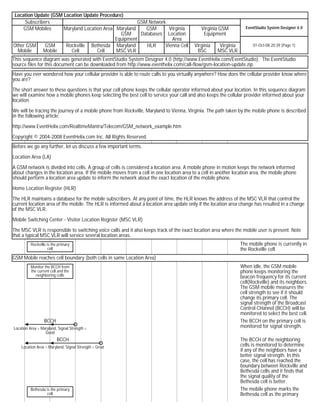
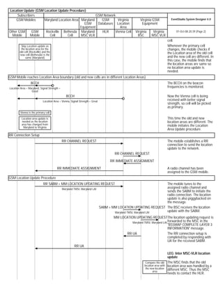
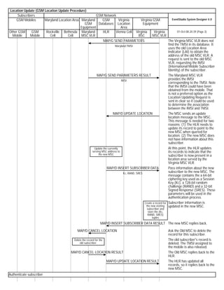
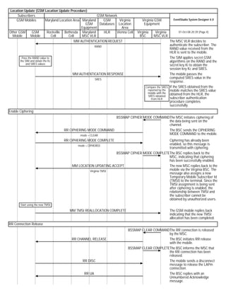
The mobile phone moves from Rockville, Maryland to Vienna, Virginia, crossing two location areas. This triggers a location update procedure where the phone authenticates with the new network in Virginia and is assigned a new temporary ID. Key steps are: 1) The phone detects it has moved to a new location area. 2) It initiates a location update including its old ID. 3) The new network authenticates the phone and updates location records. 4) The phone is assigned a new temporary ID.
Practical handoff considerations in mobile cellular systems include:
1. Using umbrella cells, where different antenna heights and power levels provide both large and small co-located cells, to minimize handoffs for high-speed users while providing channels for low-speed users.
2. The problem of cell dragging for pedestrian users with line-of-sight to the base station, whose strong signals may prevent necessary handoffs.
3. CDMA systems allow soft handoffs where the same channel is shared across cells, enabling evaluation of signals from multiple base stations to select the best one.
Channel planning is critical for wireless network deployment. Poor planning can lead to unreliable networks with low capacity and performance. Assigning appropriate radio channels to each base station while determining frequency reuse ratios and cell separation distances is an important but difficult process. Cellular systems do not always follow homogeneous path loss models. Control channels are vital and generally use more conservative frequency reuse than voice channels. Cell breathing occurs as CDMA cell sizes dynamically shrink and grow depending on the number of users in the cell. Near-far problem and reverse link power control are also important CDMA concepts.
The document discusses handover in mobile networks. Handover is the process of transferring a mobile device's connection from one base station to another as the device moves through the network coverage area. There are different types of handover including intra-cell, inter-cell, inter-BSC, and inter-MSC handovers. The base station controller monitors signal strength and quality and initiates a handover when the device would be better served by a new base station to avoid call drops and ensure quality of service.
This document discusses handoff management in wireless networks. It covers handoff basics, detection, assignment and examples of handoff in GSM networks. It also discusses handoff requirements and goals such as latency, scalability and quality of service. Advanced issues covered include handoff failure, different types of radio link transfers during handoff, and differences between hard and soft handoff.
The document discusses the benefits of a private voice-data telecom network (PVDTN) system. It outlines how PVDTN can save organizations up to 75% of present telecom costs, improve decision making and security, and virtually convert multi-location organizations into single offices. The document provides diagrams illustrating sample network configurations and topologies that can be implemented using PVDTN to integrate voice, fax and data communications across locations.
The document discusses different types of location updating procedures in mobile networks:
1. Location updating type normal occurs when a mobile subscriber (MS) moves to a new location area and needs to update the network of its new location.
2. IMSI attach is used when the MS powers back on in the same location area it was in when it entered detached mode.
3. Periodic registration is used to avoid unnecessary paging and prevent database failures. The MS registers at periodic intervals set by the network operator, from every 6 minutes to every hour.
This document discusses paging and location update procedures in cellular networks. It defines key terms like MSC, VLR, HLR, TMSI, LA, LAI, and describes how location areas are configured and how location updates and paging work. When a mobile moves to a new location area or PLMN, it performs a location update by sending a message to the new MSC/VLR, which updates the subscriber's HLR. Periodic and random location updates also allow the network to track mobile locations. Paging is used to find mobiles and deliver incoming calls based on location registration information.
This document provides guidance on optimizing the paging success rate key performance indicator (KPI) in GSM base station subsystem (BSS) networks. It defines paging success rate as the ratio of paging responses received to paging requests sent. The document outlines potential causes of low paging success rates such as hardware faults, transmission problems, parameter misconfiguration, interference, coverage issues, and uplink/downlink imbalance. It then provides detailed analysis and optimization procedures to address each cause. Case studies demonstrate how to resolve real-world paging success rate issues.
The document discusses GSM signaling and mobile signaling. GSM signaling defines communications between the mobile and network using different protocols across interfaces. Mobile signaling involves the mobile searching for frequencies, synchronizing, downloading information, selecting a network, and signaling to the network by sending a service request when a call is made.
This document provides an overview of call routing in GSM networks. It discusses key components like the Home Location Register (HLR) and Visitor Location Register (VLR) that store subscriber data. It then describes different call routing scenarios like mobile originated calls, mobile terminated calls, and roaming calls. It explains the signaling process and interactions between network elements like the mobile station, base station, MSC, HLR, and other switches. Finally, it briefly discusses the handover process to transfer calls between base stations when a mobile changes location.
The document outlines basic call flows for location updates, mobile originating calls (MOC), mobile terminating calls (MTC), and IP calls. It describes the key steps as:
1) Location update involves identity response, authentication between the SIM and MSC, update location requests, and ciphering.
2) For MOC, the mobile station sends a setup message with the dialed number, the MSC sends a send routing information message to the HLR, and the HLR responds with routing instructions allowing the call to be connected.
3) For MTC, the MSC requests a roaming number from the HLR, the HLR provides a number and the MSC pages the mobile station to alert
The document provides an overview of GSM, GPRS, UMTS, HSDPA and HSUPA protocols and call flows. It describes the architecture, interfaces and protocols of each generation at the physical, data link and network layers. Key protocols discussed include LAPD, RR, MM, CM, SNDCP, GTP, RLC, MAC, RRC. Call flows for basic call origination, authentication, data transfer and detach procedures are illustrated for each network. The document also introduces HSDPA and HSUPA enhancements to UMTS such as new channels, scheduling functionality and H-ARQ protocol.
This document discusses paging in a mobile network. It describes the paging process, including the messages exchanged between the mobile station, base station, radio network controller, and visitor location register. It also covers paging scenarios like successful paging, absent subscriber paging, and paging during restoration of the visitor location register. Programmable parameters that control aspects of the paging process are defined, such as the number of paging attempts, timer for awaiting the response to paging, and conditions for the search procedure. Finally, potential unsolicited messages related to issues in the paging process are listed.
The document provides information on 2G/3G network architectures. It discusses 2G GSM network architecture including components like the BTS, BSC, MSC, VLR, HLR and interfaces like A, Abis, and GSM. It then covers GPRS and EDGE network enhancements, components like the SGSN, GGSN, and interfaces like Gn and Gi. Finally, it discusses UMTS network technologies like W-CDMA and HSDPA that improved data rates.
This document provides an overview of SDCCH congestion rate in GSM networks, including its definition, measurement points, contributing factors, and optimization methods. It defines SDCCH congestion rate as the ratio of failed SDCCH seizures due to busy SDCCH channels to total SDCCH requests. The document then outlines several potential causes of high SDCCH congestion rate, such as hardware faults, insufficient signaling resources, improper data configuration, and interference. Finally, it proposes a procedure for analyzing SDCCH congestion that involves checking hardware, channel configuration, data configuration, and the Um interface quality.
The document provides guidance on optimizing the TCH congestion rate KPI in GSM networks. It defines TCH congestion rate, discusses its impacts, and identifies potential influencing factors including network capacity, faults, interference, parameter settings, third-party devices, and software versions. The document then outlines an analysis procedure and provides optimization methods addressing each influencing factor, such as traffic balancing, hardware troubleshooting, interference reduction, parameter tuning, and capacity expansion. Example cases are also presented.
This document summarizes GSM architecture and call flows, including inter-MSC and intra-MSC call flows. Inter-MSC call flow occurs between two different MSCs, while intra-MSC call flow is between two BSCs within the same MSC. The inter-MSC call flow involves signaling between the BSC, MSC-O, MSC-T, HLR, and RNC to set up and release the call bearers. The intra-MSC call flow involves signaling between the MS-O, BSC-O, MSC/VLR, MGW, HLR, BSC-T, and MS-T to authenticate, set up, and release call bearers within a single MSC
This document provides an overview and optimization guidance for reducing the SDCCH call drop rate in GSM networks. It defines SDCCH call drop rate, lists factors that can affect it such as hardware failures, interference and parameter settings, and provides an analysis process and solutions to address a high SDCCH call drop rate. The solutions involve checking for issues with hardware, transmissions, software versions, parameter settings, interference, coverage, antenna systems and uplink/downlink imbalance. The document also includes examples of optimizing SDCCH call drop rate in specific cases.
Paging is the mechanism by which the network notifies a UE that it has data to send. The UE periodically wakes from idle mode to check for paging messages. If the UE ID in the paging message matches the UE, it notifies upper layers which may initiate a connection for incoming calls or other data. Paging messages are sent by the MME to eNodeBs and contain UE IDs, domain information, and indications for system information changes or emergency notifications.
The document discusses key performance indicators (KPIs) for GSM base station subsystem (BSS) networks, including the paging success rate KPI. It defines paging success rate, describes factors that affect it such as coverage, interference, and traffic volume. The document also discusses network parameters that impact paging success rate, such as paging times/intervals, paging based on location area versus all cells, and mobility management parameters like T3212. The goal is to understand KPI measurement points and constraints in order to optimize network performance.
This document provides a method for optimizing the handover success rate (HOSR) on GSM BSS networks. It analyzes factors that affect HOSR, such as hardware failures, configuration issues, interference and coverage problems. The document describes processes for locating HOSR problems and provides optimization methods, including automatic neighboring cell configuration. Case studies demonstrate issues such as failed handovers due to incorrect BSIC decoding or timer configuration. Logs and traffic data are sources for analyzing HOSR performance.
This document summarizes key concepts related to location management in GSM networks. It defines IMEI as a unique 15-digit number assigned to mobile devices used for identification and security. It explains that MSISDN is the subscriber's phone number stored in the HLR and SIM. TMSI is a temporary ID assigned during a subscriber's presence in an area to replace IMSI for increased privacy. LAI is the unique ID of a location area broadcast to help the mobile station determine if it has changed locations.
How to unlock alcatel one touch fierce 7024w by unlock coderscooldesire
If your Alcatel One Touch Fierce 7024w is locked to use with specific carrier, and you are not able to use it another SIM card, most probably you want to unlock it for different SIM card providers. If you buy your Alcatel One Touch Fierce with networks like AT&T, T-Mobile etc. on a contract, then you phone is Sim Locked with that network. You can unlock your device to use with any compatible gsm network and save significant cost.
An observer is watching someone and notes that it is 08:53 and the person being watched is doing nothing, as they often do at that time. The observer expresses frustration at the watched person's lack of activity.
1. Total assets for Sony increased 18.23% from 2012 to 2013, while total liabilities increased 7.5%, resulting in total equity growth of 23.49%.
2. Long-term liabilities for Sony increased 32.79% from 2012 to 2013, a higher rate than the 27.39% increase for Samsung over the same period.
3. Sony's long-term debt decreased 33.33% from 2012 to 2013, a larger decline than Samsung's long-term debt decrease of 3.33% over that time.
Feature I wrote on Las Vegas for the July 2008 issue of Travel Digest. I travelled to this destination as part of attending a travel industry conference which I also reported on.
1. This document describes the call setup process for a GSM originating call made from a mobile user to a landline subscriber.
2. It involves establishing a radio resource connection between the mobile station and base station, authenticating and ciphering the connection, and setting up the voice channel and call.
3. The key steps are radio channel allocation, call signaling transmission to the mobile switching center, routing the call to the public switched telephone network, alerting and connecting the called party, and releasing the call resources on completion.
The document describes the infrastructure and processes that enable cellular communication systems. Key components include:
- Base stations that transmit and receive signals and connect to a base station controller.
- Authentication centers and equipment registers that verify user identities and equipment.
- Home and visitor location registers that track user locations to route calls and support mobility.
- Registration and handoff processes allow users to move between base stations and be reached on their cell phone number anywhere on the network. Location tracking, signaling between registers, and rerouting enable seamless roaming across large areas.
1. Call routing in GSM involves routing calls from the mobile station (MS) through the base station subsystem (BSS) and mobile switching center (MSC) when originating a call or routing an incoming call to the MS.
2. For outgoing calls, the MS sends the dialed number to the BSS which sends it to the MSC. The MSC checks if the MS is allowed the service and asks the BSS to allocate resources before routing the call through the gateway MSC and local exchange.
3. For incoming calls, the call is first sent to the gateway MSC which signals the home location register (HLR). The HLR provides the visiting location register (VLR) which informs the
This document discusses mobile communications and cellular systems. It describes the basic components like subscribers, base stations, and different communication modes. It then explains the fundamentals of cellular systems including cell structure, base stations, mobile units, and wireless components. Finally, it outlines the process of making and receiving telephone calls through a cellular network including call handoff between base stations.
05. EEE 439 Communication Systems II - Cellular Communications.pdfjilanur93
The document discusses various topics related to cellular networks including:
- The history of cellular networks from 1G to 5G technologies.
- Components of cellular networks including mobile stations, base stations, switches, and databases for tracking user locations.
- Concepts like cells, frequency reuse, and handoffs which allow cellular networks to efficiently use limited radio spectrum and maintain connectivity as users move.
- Models for radio propagation including free space path loss which predicts signal strength over distance in line-of-sight conditions.
In 3 sentences or less, this summary outlines some of the key technological developments in cellular networks and fundamental concepts that have enabled their widespread adoption and use.
The document summarizes the GSM inter-BSC intra-MSC handover call flow where a mobile phone moves from the Rockville cell to the Bethesda cell while on a call. The Rockville BSC detects the mobile will have better signal in the Bethesda cell and sends a handover required message to the MSC. The MSC sends a handover request to the Bethesda BSC which allocates a channel. The Bethesda BSC sends a handover command to the mobile via the Rockville BSC. The mobile then tunes to the new channel and completes the handover while the call path is switched to maintain the call.
The document summarizes the GSM inter-BSC intra-MSC handover call flow where a mobile phone moves from the Rockville cell to the Bethesda cell while on a call. The Rockville BSC detects the mobile will have better signal in the Bethesda cell and sends a handover required message to the MSC. The MSC sends a handover request to the Bethesda BSC which allocates a channel. The Bethesda BSC sends a handover command to the mobile via the Rockville BSC. The mobile then tunes to the new channel and completes the handover process while maintaining the active call.
Similar to Gsm location update_sequence_diagram (9)
2. Location Update (GSM Location Update Procedure)
Subscribers GSM Network
GSM Mobiles Maryland Location Area Maryland GSM Virginia Virginia GSM EventStudio System Designer 4.0
GSM Databases Location Equipment
Equipment Area
Other GSM GSM Rockville Bethesda Maryland HLR Vienna Cell Virginia Virginia 01-Oct-08 20:39 (Page 2)
Mobile Mobile Cell Cell MSC VLR BSC MSC VLR
cell.
Skip Location update as Whenever the primary cell
the location area for the changes, the mobile checks if
old cell (Rockville) and the the Location area of the old cell
new cell (Bethesda) is the
same (Maryland) and the new cell are different. In
this case, the mobile finds that
the location areas are same so
no location area update is
needed.
GSM Mobile reaches Location Area boundary (old and new cells are in different Location Areas)
BCCH The BCCH on the beacon
Location Area = Maryland, Signal Strength = frequencies is monitored.
Good
BCCH Now the Vienna cell is being
Location Area = Vienna, Signal Strength = Great received with better signal
strength, so cell will be picked
as primary.
Vienna is the primary cell
Location area update is This time the old and new
needed as the location location areas are different. The
area has changed from mobile initiates the Location
Maryland to Virginia
Area Update procedure.
RR Connection Setup
RR CHANNEL REQUEST The mobile establishes a RR
connection to send the location
update to the network.
RR CHANNEL REQUEST
RR IMMEDIATE ASSIGNMENT
RR IMMEDIATE ASSIGNMENT A radio channel has been
assigned to the GSM mobile.
GSM Location Update Procedure
RR SABM + MM LOCATION UPDATING REQUEST The mobile tunes to the
Maryland TMSI, Maryland LAI assigned radio channel and
sends the SABM to initiate the
radio connection. The location
update is also piggybacked on
the message.
SABM + MM LOCATION UPDATING REQUEST The BSC receives the location
Maryland TMSI, Maryland LAI update with the SABM.
MM LOCATION UPDATING REQUESTThe location updating request is
Maryland TMSI, Maryland LAI forwarded to the MSC in the
"BSSMAP COMPLETE LAYER 3
INFORMATION" message.
RR UA The RR connection setup is
completed by responding with
UA for the received SABM.
RR UA
LEG: Inter MSC-VLR location
update
Compare the old The MSC finds that the old
location area with location area was handled by a
the new location different MSC. Thus the MSC
area
needs to contact the HLR.
3. Location Update (GSM Location Update Procedure)
Subscribers GSM Network
GSM Mobiles Maryland Location Area Maryland GSM Virginia Virginia GSM EventStudio System Designer 4.0
GSM Databases Location Equipment
Equipment Area
Other GSM GSM Rockville Bethesda Maryland HLR Vienna Cell Virginia Virginia 01-Oct-08 20:39 (Page 3)
Mobile Mobile Cell Cell MSC VLR BSC MSC VLR
MAP/G SEND PARAMETERS The Virginia MSC VLR does not
Maryland TMSI find the TMSI in its database. It
uses the old Location Area
Indicator (LAI) to obtain the
address of the old MSC VLR. A
request is sent to the old MSC
VLR, requesting the IMSI
(International Mobile Subscriber
Identity) of the subscriber.
MAP/G SEND PARAMETERS RESULT The Maryland MSC VLR
IMSI provides the IMSI
corresponding to the TMSI. Note
that the IMSI could have been
obtained from the mobile. That
is not a preferred option as the
Location Updating Request is
sent in clear so it could be used
to determine the association
between the IMSI and TMSI.
MAP/D UPDATE LOCATION The MSC sends an update
location message to the MSC.
This message is needed for two
reasons: (1) The HLR needs to
update its record to point to the
new MSC when queried for
location. (2) The new MSC does
not have information about this
subscriber.
Update the currently At this point, the HLR updates
serving MSC address to its records to indicate that the
the new MSC subscriber is now present in a
location area served by the
Virginia MSC VLR.
MAP/D INSERT SUBSCRIBER DATA Pass information about the new
Kc, RAND, SRES subscriber to the new MSC. The
message contains the a 64-bit
ciphering key used as a Session
Key (Kc), a 128-bit random
challenge (RAND) and a 32-bit
Signed Response (SRES). These
parameters will be used in the
authentication process.
Create a record for Subscriber information is
the new visiting updated in the new MSC.
subscriber and
store the (Kc,
RAND, SRES)
tuples
MAP/D INSERT SUBSCRIBER DATA RESULT The new MSC replies back.
MAP/D CANCEL LOCATION Ask the Old MSC to delete the
record for this subscriber.
Delete the record for the The old subscriber's record is
old subscriber. deleted. The TMSI assigned to
the mobile is also released.
MAP/D CANCEL LOCATION RESULT The Old MSC replies back to the
HLR.
MAP/D UPDATE LOCATION RESULT The HLR has updated all
records, so it replies back to the
new MSC.
Authenticate subscriber
4. Location Update (GSM Location Update Procedure)
Subscribers GSM Network
GSM Mobiles Maryland Location Area Maryland GSM Virginia Virginia GSM EventStudio System Designer 4.0
GSM Databases Location Equipment
Equipment Area
Other GSM GSM Rockville Bethesda Maryland HLR Vienna Cell Virginia Virginia 01-Oct-08 20:39 (Page 4)
Mobile Mobile Cell Cell MSC VLR BSC MSC VLR
MM AUTHENTICATION REQUEST The MSC VLR decides to
RAND authenticate the subscriber. The
RAND value received from the
HLR is sent to the mobile.
Pass the RAND value to The SIM applies secret GSM
the SIM and obtain the Kc algorithms on the RAND and the
and SRES values secret key Ki to obtain the
session key Kc and SRES.
MM AUTHENTICATION RESPONSE The mobile passes the
SRES computed SRES value in the
response.
Compare the SRES If the SRES obtained from the
reported by the mobile matches the SRES value
mobile with the obtained from the HLR, the
SRES obtained
from HLR subscriber authentication
procedure completes
successfully.
Enable Ciphering
BSSMAP CIPHER MODE COMMANDThe MSC initiates ciphering of
the data being sent on the
channel.
RR CIPHERING MODE COMMAND The BSC sends the CIPHERING
mode = CLEAR MODE COMMAND to the mobile.
RR CIPHERING MODE COMPLETE Ciphering has already been
mode = CIPHERED enabled, so this message is
transmitted with ciphering.
BSSMAP CIPHER MODE COMPLETEThe BSC replies back to the
MSC, indicating that ciphering
has been successfully enabled.
MM LOCATION UPDATING ACCEPT The new MSC replies back to the
Virginia TMSI mobile via the Virginia BSC. The
message also assigns a new
Temporary Mobile Subscriber Id
(TMSI) to the terminal. Since the
TMSI assignment is being sent
after ciphering is enabled, the
relationship between TMSI and
the subscriber cannot be
obtained by unauthorized users.
Start using the new TMSI
MM TMSI REALLOCATION COMPLETE The GSM mobile replies back
indicating that the new TMSI
allocation has been completed.
RR Connection Release
BSSMAP CLEAR COMMANDThe RR connection is released
by the MSC.
RR CHANNEL RELEASE The BSC initiates RR release
with the mobile.
BSSMAP CLEAR COMPLETEThe BSC informs the MSC that
the RR connection has been
released.
RR DISC The mobile sends a disconnect
message to release the LAPm
connection.
RR UA The BSC replies with an
Unnumbered Acknowledge
message.