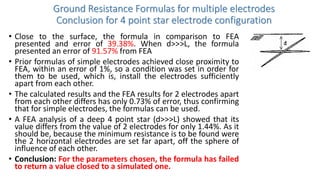
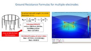
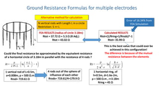
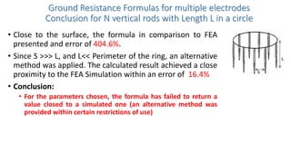
Downloaded 100 times
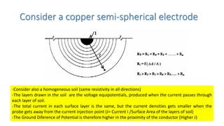
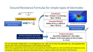
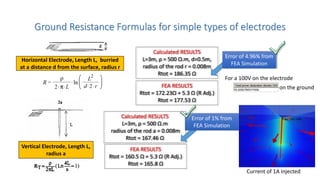
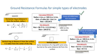
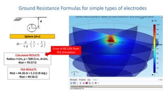
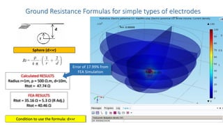
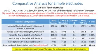
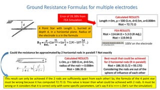
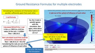
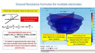
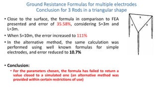
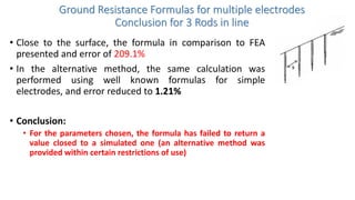


- The document discusses ground modeling and formulas for calculating ground resistance of various electrode configurations using finite element analysis software. - Formulas for simple electrode shapes like horizontal rods, vertical rods, rings, and semi-spheres were found to have errors within 1-5% of FEA results when conditions of separation between electrodes were met. - Formulas for more complex configurations like 4-point stars, vertical rods in a circle, and 3 rods in a triangle performed poorly compared to FEA, with errors over 30%. Alternative calculation methods treating the configurations as combinations of simple electrodes in parallel produced better results within 10-16% of FEA.