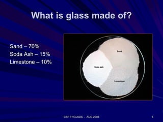
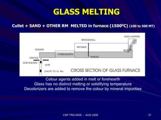
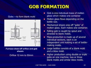
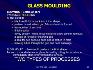
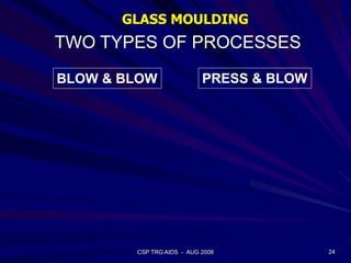
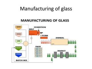
This document provides an overview of the course "Glass Metal and Textile Based packaging". It includes the syllabus, extended syllabus details, course outcomes, session plans, lecture notes, evaluations, and chapter details with learning objectives. The course aims to teach students about different packaging materials like glass, metal, and textiles as well as glass manufacturing processes, types of glass, properties, advantages and disadvantages of glass, glass classification, and defects in glass containers. It contains 10 chapters and the document maps the learning objectives of each chapter to the course outcomes.

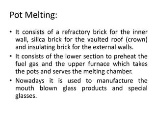
![IMI-NFG Course on Processing of Glass - Lecture 2: Industrial glass melting and fining processes
mathieu.hubert@celsian.nl 29
-2
0
2
4
6
8
10
600 650 700 750 800 850 900 950 1000
Temperature [°C]
Chemicalenergyconsumptionrate[kJ·kgbatch
-1
·K
-1
]
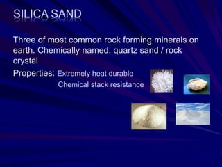
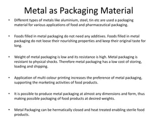
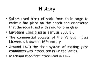
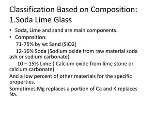
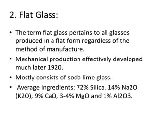
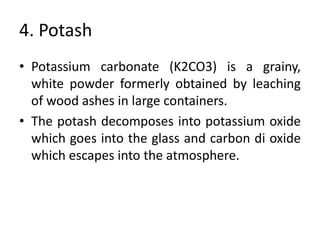
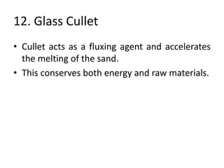
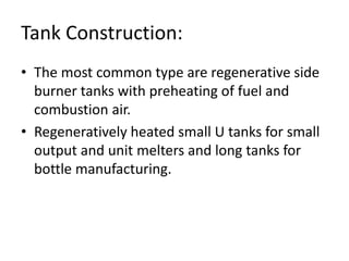
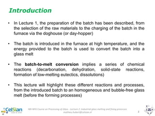
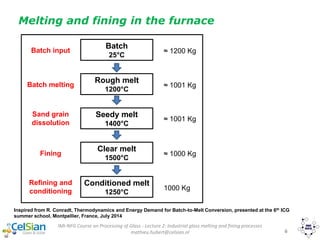
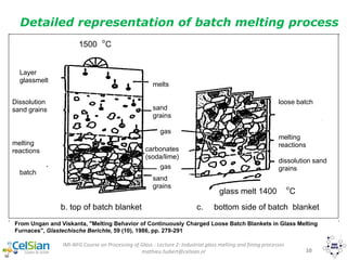
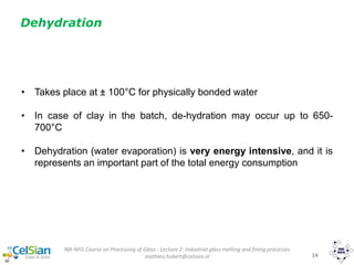
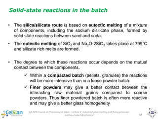
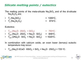
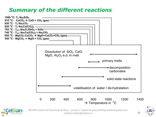
Overall chemical energy demand
MgCO3·CaCO3(s) -> MgO(s) + CO2(g) + CaCO3(s)
CaCO3(s) -> CaO(s) + CO2(g)
Na2CO3(s) + SiO2(q) -> Na2O·SiO2(s) + CO2(g)
Na2CO3(s) -> Na2CO3(l)
Na2CO3(l) + SiO2(q) -> Na2O·SiO2(s) + CO2(g)
Na2O·SiO2(s) + SiO2(q) -> NS(l)
CaO(s) + melt
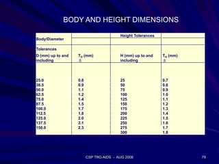
Chemical energy demand](https://image.slidesharecdn.com/chapter1-190109040244/85/Glass-as-Packaging-Materials-106-320.jpg)
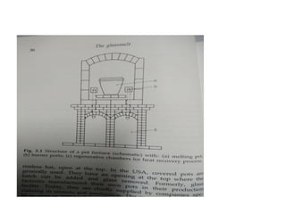
![IMI-NFG Course on Processing of Glass - Lecture 2: Industrial glass melting and fining processes
mathieu.hubert@celsian.nl 30
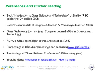
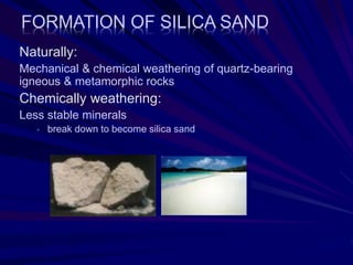
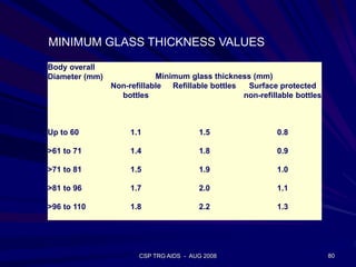
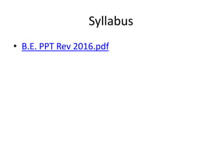
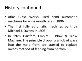
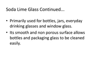
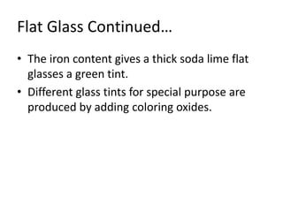
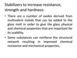
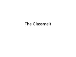
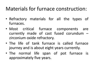
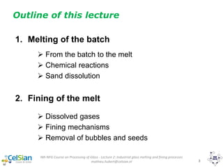
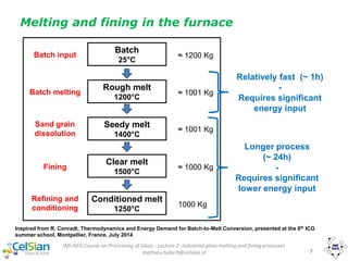
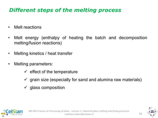
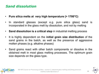
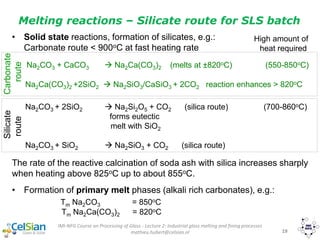
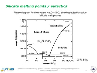
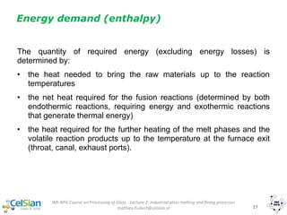
Effect of cullet on required energy:
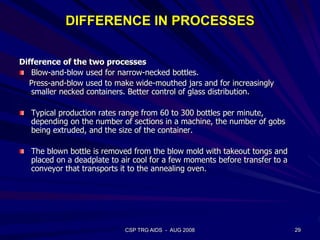
• Less reaction energy and less gaseous reaction products
• Faster batch heating due to better heat transfer
Soda lime
glass
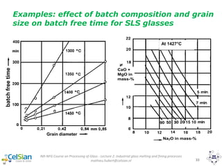
[kJ/kg]
Lead glass
(19 % PbO)
[kJ/kg]
Sodium boro-
silicate glass
(8 % B2O3)
[kJ/kg]
E-glass
[kJ/kg]
Tangible heat of melt
(0 - 1400 oC)
Reaction heat
Tangible heat volatile
reaction products
(0 - 1500 oC)
1775
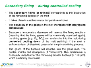
487
293
1603
403
166
1609
412
140
1588
roughly 400
577
TOTAL 2555 2172 2161 2565
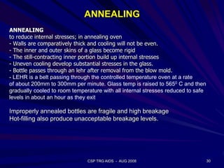
Typical values for theoretical heat demand of
several batch types (without cullet)](https://image.slidesharecdn.com/chapter1-190109040244/85/Glass-as-Packaging-Materials-107-320.jpg)
![IMI-NFG Course on Processing of Glass - Lecture 2: Industrial glass melting and fining processes
mathieu.hubert@celsian.nl 32
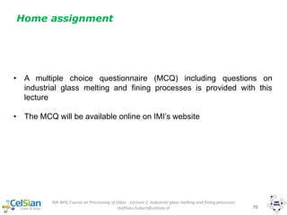
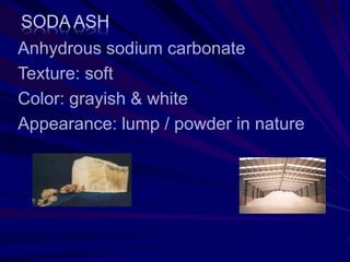
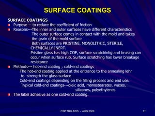
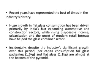
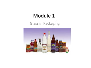
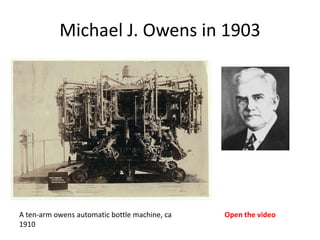
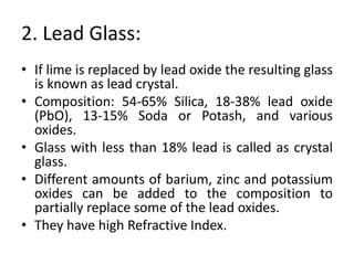
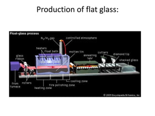
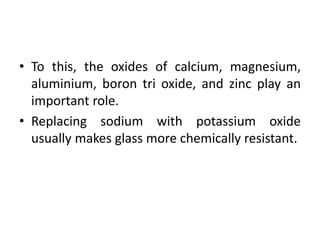
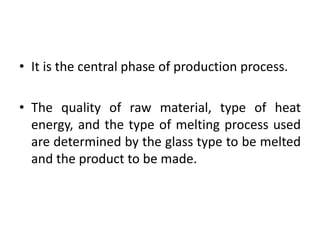
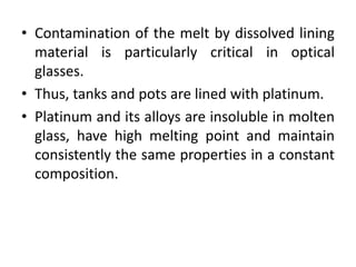
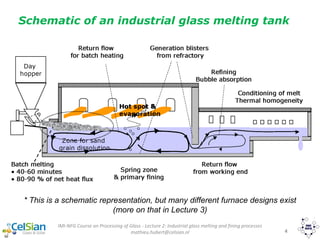
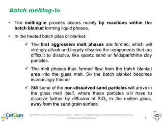
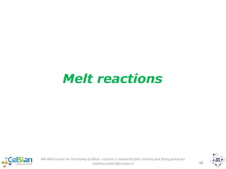
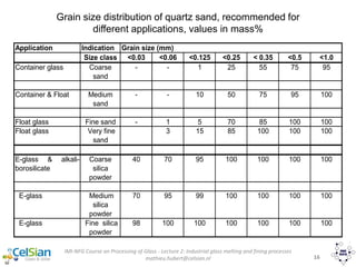
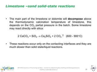
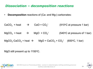
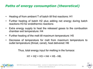
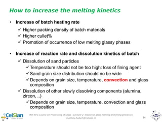
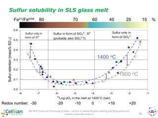
Dissolution rate of sand grains in silicate melt
• The dissolution rates of single silica grains in silicate melts are
diffusion-controlled
• The SiO2 at the grain surface dissolved in the surrounding melt has
to be transferred into the melt by diffusion.
• The driving force for the
diffusion process is the
difference of the
equilibrium concentration
of SiO2 in the molten glass
(maximum SiO2 solubility in
the glass melt at that
temperature) that exists
at the interface of the silica
quartz sand
grain
glass melt
Ce is maximum SiO2 solubility (depends
on glass composition and temperature)
reaction SiO2 with molten glass
Ws = concentration SiO2 in melt =
about 72 mass%
dissolution of SiO2
SiO2-diffusion
We= concentration SiO2 at
interface
85 mass%
[SiO2] = C in mass%](https://image.slidesharecdn.com/chapter1-190109040244/85/Glass-as-Packaging-Materials-109-320.jpg)


![IMI-NFG Course on Processing of Glass - Lecture 2: Industrial glass melting and fining processes
mathieu.hubert@celsian.nl 46
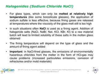
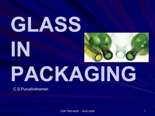
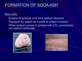
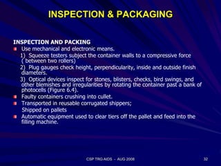
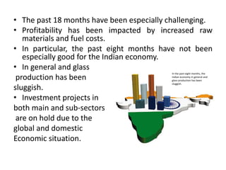
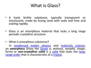
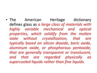
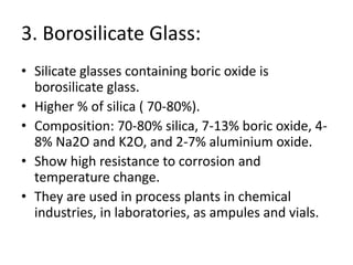
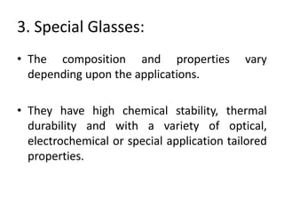
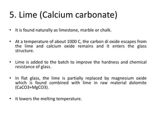
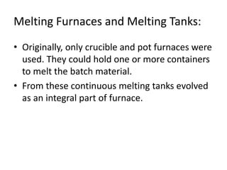
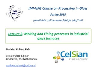
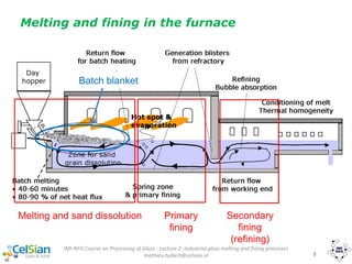
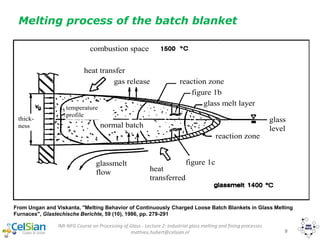
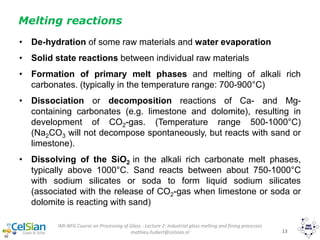
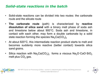
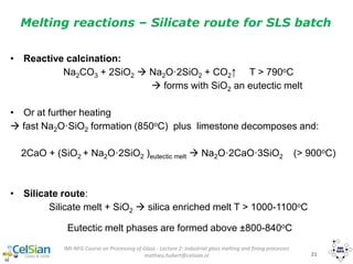
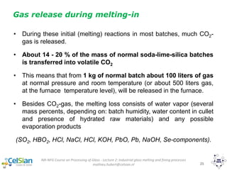
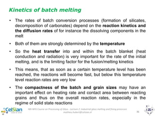
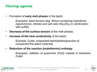
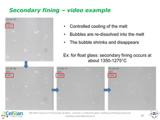
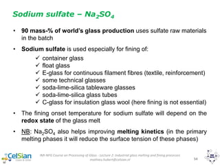
Often used fining agent: Sodium sulfate Na2SO4 (salt cake)
Primary fining – Example sulfate fining
Fining reaction: T > TFining onset
Na2SO4(m) Na2O(m)+SO2 (gas)+1/2 O2 (gas)
Dilution of N2 & CO2 in bubble by fining gases
SO2
CO2
O2
N2
Stripping of CO2
and N2 from melt
Cm CO2
Cm N2
][SO
pOpSO
K
3
22'
=](https://image.slidesharecdn.com/chapter1-190109040244/85/Glass-as-Packaging-Materials-123-320.jpg)
![IMI-NFG Course on Processing of Glass - Lecture 2: Industrial glass melting and fining processes
mathieu.hubert@celsian.nl 47
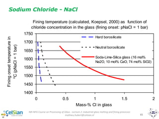
Acceleration of bubble ascension
𝑣 𝑎𝑠𝑐𝑒𝑛𝑠𝑖𝑜𝑛 =
𝑐. 𝜌. 𝑔. 𝑅2
η
ρ : density of the glass melt [Kg/m3]
η : viscosity of the glass melt [Pa.s]
R : bubble radius [m]
g : gravity [9.81 m/s2]
c : factor (e.g. Stokes c =2/9)](https://image.slidesharecdn.com/chapter1-190109040244/85/Glass-as-Packaging-Materials-124-320.jpg)
![IMI-NFG Course on Processing of Glass - Lecture 2: Industrial glass melting and fining processes
mathieu.hubert@celsian.nl 48
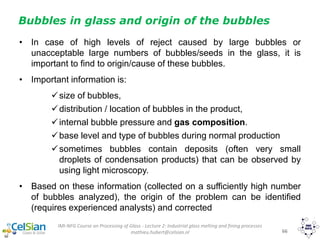
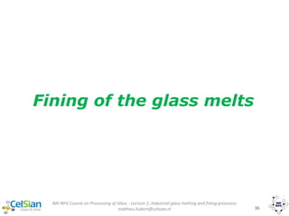
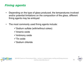
Primary fining
Time to reach glass surface (1 meter)
0
50
100
150
200
250
0 100 200 300 400 500
Bubble diameter [μm]
Timetoreachglasslevelat1meter[h]
1350 OC
1400 OC
1450 OC
1500 OC
Float glass melt
At higher temperatures
=> melt with lower viscosity](https://image.slidesharecdn.com/chapter1-190109040244/85/Glass-as-Packaging-Materials-125-320.jpg)
![IMI-NFG Course on Processing of Glass - Lecture 2: Industrial glass melting and fining processes
mathieu.hubert@celsian.nl 56
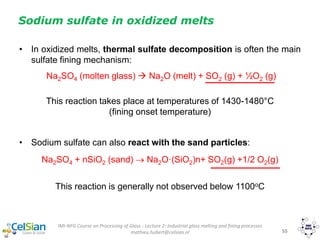
Sodium sulfate in reduced melts
• Some sulfate reacts with reducing agents in batch (cokes or oganic
contamination, i.e. carbon). Examples of reactions:
2 C + Na2SO4 → 2 CO + Na2S
4 CO + Na2SO4 → 4 CO2 + Na2S
4C + Na2SO4 → 4 CO + Na2S
• Then, sulfate-sulfide reactions occur in the temperature interval
1140-1350°C (one example below, but other reactions are also
possible)
xNa2S + yNa2SO4 + pSiO2 (Na2O)(x+y)·(SiO2)p+ (x+y) SO2 + [(y-3x)/2] O2
formation of sulfides S2-
around 700-800°C](https://image.slidesharecdn.com/chapter1-190109040244/85/Glass-as-Packaging-Materials-133-320.jpg)
![IMI-NFG Course on Processing of Glass - Lecture 2: Industrial glass melting and fining processes
mathieu.hubert@celsian.nl 58
0
2
4
6
8
10
500 600 700 800 900 1000 1100 1200 1300 1400 1500
Temperature [°C]
ConcentrationCO2inpurge
gas[vol%]
0
200
400
600
800
1000
ConcentrationCO,O2&SO2
inpurgegas[volppm]
CO2
CO
SO2
O2
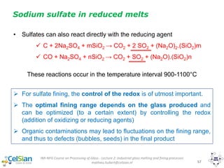
Gas evolution for an oxidized batch with sulfates
Reaction of sulfide
and sulfate
Thermal sulfate
decomposition](https://image.slidesharecdn.com/chapter1-190109040244/85/Glass-as-Packaging-Materials-135-320.jpg)
![IMI-NFG Course on Processing of Glass - Lecture 2: Industrial glass melting and fining processes
mathieu.hubert@celsian.nl 59
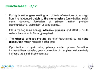
Gas evolution for an reduced batch with sulfates
0
2
4
6
8
10
500 600 700 800 900 1000 1100 1200 1300 1400 1500
Temperature [°C]
ConcentrationCO2inpurge
gas[vol%]
0
200
400
600
800
1000
ConcentrationCO&SO2in
purgegas[volppm]
CO2
CO
SO2
Direct reaction
sulfate with
reducing
component
2n242
2422
4SO)(SiOO)(Na
nSiOSO3NaSNa
](https://image.slidesharecdn.com/chapter1-190109040244/85/Glass-as-Packaging-Materials-136-320.jpg)