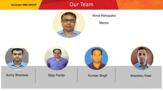
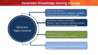
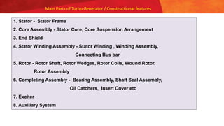
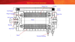
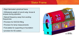
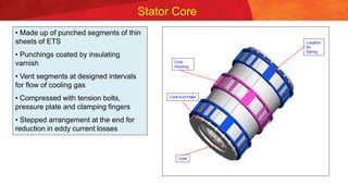
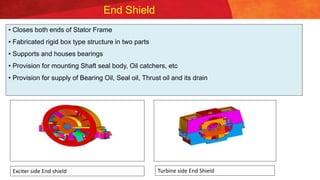
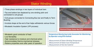
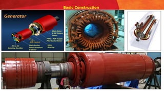
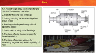
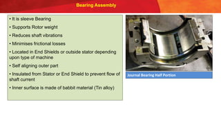
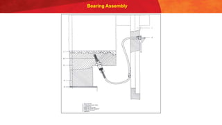
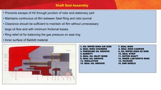
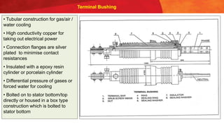
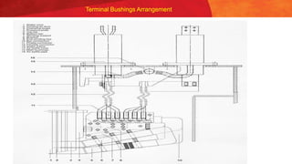
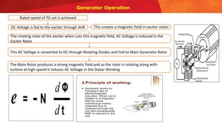
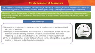
11/16/2022
Knowledge Sharing Program
on
Generator basics, Excitation, Protection System, Overhauling
Maintenance
Presented by:
Sunny Bhardwaj, Bijay Panda ,Kundan Singh and Shambhu Patel
Our Team
Generator SME GROUP
Sunny Bhardwaj Bijay Panda Kundan Singh Shambhu Patel
Nimai Mahapatra
Mentor
Generator Knowledge sharing Journey
Generator
Topics Covered
Generator Basics:
History, working Principle, classification, Insulation,
Construction, Synchronisation, Bearing, NGT
Excitation System and AVR:
Definition, Types, Component, Difference between
Static & Brushless exc system, Advantage
Protection System:
Importance, Protectives relay , Schemes
Overhauling and Maintenance:
Generator testing ,condition , principle, Instruments
Required
Generator Basics and Design Aspect
Name Plate Details
Name Plate of Generator Turbine House
Introduction
A generator is a device that converts motive power (mechanical energy) into electrical power for
use in an external circuit.
Sources of mechanical energy include :-
Steam turbines, Gas turbines, Water turbines and Internal combustion engines.
We at Hindalco, are using Steam Turbine and Internal Combustion Engine as source of Mechanical Energy
GENERATOR
“The e.m.f. induced in a
conductor is proportional
to the rate at which the
magnetic field lines are
cut by the conductor.”
Faraday’s law of
electromagnetic
induction.
Working Principle :
Introduction
History of Development - Globally
 First single phase generator of 75 KW 1888
 First 3 phase generator, salient pole 1900
 First turbo type 3 phase 25 MW generator 1912
 UK made 50 Hz as standard frequency for Europe 1925
 First Hydrogen cooled 3 phase 30 MW generator 1937
 First Hydrogen cooled TG with direct cooling of rotor 1949
 First generator with water cooled stator winding 1956
 First generator with water cooling for stator and rotor wdg 1959
Power Output of Turbogenerator
P  D2 . L . B . A . n
P Power in MVA
D Bore Diameter of Core in meters
L Length of Active Rotor Body in meters
B Air Gap Flux Density in Tesla
A Stator Ampere-Turn Loading in Amp./meter
n Speed in rpm
Main Parts of Turbo Generator / Constructional features
1. Stator - Stator Frame
2. Core Assembly - Stator Core, Core Suspension Arrangement
3. End Shield
4. Stator Winding Assembly - Stator Winding , Winding Assembly,
Connecting Bus bar
5. Rotor - Rotor Shaft, Rotor Wedges, Rotor Coils, Wound Rotor,
Rotor Assembly
6. Completing Assembly - Bearing Assembly, Shaft Seal Assembly,
Oil Catchers, Insert Cover etc
7. Exciter
8. Auxiliary System
Main Parts of Turbo Generator
Stator
Stator Core
End Shield
Rotor
Wdg Overhang
Bearing
Shaft Seal
Terminal Bushing
Oil Catcher
Cooler
Rotor fan
Insert
Cover
Stator Frame
• Rigid fabricated cylindrical frame
• Withstands weight of core & wdg, forces &
torques during operation
• Natural frequency away from exciting
frequencies
• Provision for H2/CO2 filling
• Provision for temp measurements
• Foot plates for supporting on foundation
• provision for H2 coolers
Stator Core
• Made up of punched segments of thin
sheets of ETS
• Punchings coated by insulating
varnish
• Vent segments at designed intervals
for flow of cooling gas
• Compressed with tension bolts,
pressure plate and clamping fingers
• Stepped arrangement at the end for
reduction in eddy current losses
Core End Plate
Core
Housing
Location
for
Spring
Core
End Shield
• Closes both ends of Stator Frame
• Fabricated rigid box type structure in two parts
• Supports and houses bearings
• Provision for mounting Shaft seal body, Oil catchers, etc
• Provision for supply of Bearing Oil, Seal oil, Thrust oil and its drain
Exciter side End shield Turbine side End Shield
Stator Winding
• Three phase windings in two layers of individual bars
• Top and bottom bar displaced by one winding pitch and
connected to coil groups
• Coil groups connected to Connecting Bus bar and finally to Term
Bushing
• Involute shape at the end of bar helps withstands various forces
• Micalastic Insulation System (VPI process)
- Micalastic good conductor of heat
- Low flamability
- High resistance to moisture and chemical action
- Accommodates thermo-mechanical stresses
- Retains properties even after years of operation
Diamond Shape Stator Bar/Coil
Temperature Monitoring inside Generator for Monitoring
by Operator using RTD method
.Measurement of Stator Winding Temperature
.Measurement of Stator Core Temperature
.Measurement of Hot Air/ Cold Air
Basic Construction
Rotor
1. A high strength alloy steel single forging
prepared by vacuum cast steel
2. Slots for housing field windings
3. Strong coupling for withstanding short
circuit forces
4. Bending critical speed away ±5% of
operating speed
5. Supported on two journal Bearings
6. Provision of axial fan/compressor for
forced ventilation
7. Provision of damper wedges for
increasing negative sequence capability of
rotor
Rotor Slot
Sub Slot
Top Slot Liner
Rotor Wedge
Conductor
Inter turn Insulation
Slot Liner
Rotor End Winding
Rotor Fan Blades
Rotor Slip Ring
Bearing Assembly
• It is sleeve Bearing
• Supports Rotor weight
• Reduces shaft vibrations
• Minimises frictional losses
• Located in End Shields or outside stator depending
upon type of machine
• Self aligning outer part
• Insulated from Stator or End Shield to prevent flow of
shaft current
• Inner surface is made of babbit material (Tin alloy)
Journal Bearing Half Portion
Bearing Assembly
Shaft Seal Assembly
• Prevents escape of H2 through junction of rotor and stationary part
• Maintains continuous oil film between Seal Ring and rotor journal
• Clearance should be sufficient to maintain oil film without unnecessary
large oil flow and with minimum frictional losses
• Ring relief oil for balancing the gas pressure on seal ring
• Inner surface of Babbitt material
1. OIL WIPER RING AIR SIDE 7. SEAL RING
2. SEAL RING CHAMBER 8. SEAL RING CARRIER
3. PRESSURE OIL GROOVE 9. OIL WIPER RING H2 SIDE
4. BABBITT 10. SEAL STRIP
5. SEAL OIL INLET BORE 11. ROTOR SHAFT
6. SEAL OIL GROOVE 12. INNER LABYRINTH RING
13. INSULATION 14. PACKING
15. SEAL OIL GROOVE 16. END SHIELD
Terminal Bushing
• Tubular construction for gas/air /
water cooling
• High conductivity copper for
taking out electrical power
• Connection flanges are silver
plated to minimise contact
resistances
• Insulated with a epoxy resin
cylinder or porcelain cylinder
• Differential pressure of gases or
forced water for cooling
• Bolted on to stator bottom/top
directly or housed in a box type
construction which is bolted to
stator bottom
Terminal Bushings Arrangement
Knowledge Check and Revision
1. Active Power of Generator is measured in?
a) KVA
b) KW
c) KVAR
2. The shape of the Generator Stator winding is?
a) Square
b) Diamond
c) Rectangle
Generator Operation
Rated speed of TG set is achieved
DC Voltage is fed to the exciter through AVR This creates a magnetic field in exciter stator
The rotating rotor of the exciter when cuts this magnetic field, AC Voltage is induced in the
Exciter Rotor
This AC Voltage is converted to DC through Rotating Diodes and Fed to Main Generator Rotor
The Main Rotor produces a strong magnetic field and as the rotor is rotating along with
turbine at high speed it induces AC Voltage in the Stator Winding
Synchronization of Generators
The process of matching parameters such as voltage, frequency, phase angle, phase sequence and waveform
of alternator (generator) or other source with a healthy or running power system is called synchronization
Generator cannot deliver power to electric power system unless its voltage, frequency and other parameters
are exactly matched with the network. Synchronization is accomplished by controlling the exciter current and
the turbine speed
Synchronoscope
 A synchroscope is used for better accuracy of synchronization and it consists of
two pairs of terminals.
 One pair of terminals marked as ‘existing’ has to be connected across the bus bar
terminals or to the existing alternator and other pair of terminals marked as
‘incoming’ has to be connected across the terminals of incoming alternator.
 The synchroscope has circular dial over which a pointer is hinged that is capable of
rotating in clockwise and anticlockwise directions.
Synchronization of Generators
• After the voltage condition is checked, the operator has to check the synchroscope. The rate at which the pointer
rotates indicates the difference of frequency between the incoming alternator and the bus bar.
• Also, the direction to which the pointer rotates (to either fast or slow) gives the information, whether the incoming
alternator frequency is higher or lower than the bus bar frequency and hence the pointer moves either fast or slow.
• The appropriate correction has to be made to control the speed of the alternator so as to bring the rate of rotation of
pointer as small as possible. Therefore, synchroscope along with voltmeters are enough for synchronization process.
However, in most of the cases a set of lights along with synchroscope is used as a double-check system.
• Modern synchronization equipments automate the whole synchronization process with the use of microprocessor
based systems that avoids manual lamps and synchroscope observations. These methods are easier to manage and
more reliable - Autosynchronizers

Generator Baisc Construction.pptx

  • 1.
    11/16/2022 Knowledge Sharing Program on Generatorbasics, Excitation, Protection System, Overhauling Maintenance Presented by: Sunny Bhardwaj, Bijay Panda ,Kundan Singh and Shambhu Patel
  • 2.
    Our Team Generator SMEGROUP Sunny Bhardwaj Bijay Panda Kundan Singh Shambhu Patel Nimai Mahapatra Mentor
  • 3.
    Generator Knowledge sharingJourney Generator Topics Covered Generator Basics: History, working Principle, classification, Insulation, Construction, Synchronisation, Bearing, NGT Excitation System and AVR: Definition, Types, Component, Difference between Static & Brushless exc system, Advantage Protection System: Importance, Protectives relay , Schemes Overhauling and Maintenance: Generator testing ,condition , principle, Instruments Required
  • 4.
    Generator Basics andDesign Aspect
  • 5.
    Name Plate Details NamePlate of Generator Turbine House
  • 6.
    Introduction A generator isa device that converts motive power (mechanical energy) into electrical power for use in an external circuit. Sources of mechanical energy include :- Steam turbines, Gas turbines, Water turbines and Internal combustion engines. We at Hindalco, are using Steam Turbine and Internal Combustion Engine as source of Mechanical Energy GENERATOR “The e.m.f. induced in a conductor is proportional to the rate at which the magnetic field lines are cut by the conductor.” Faraday’s law of electromagnetic induction. Working Principle : Introduction
  • 7.
    History of Development- Globally  First single phase generator of 75 KW 1888  First 3 phase generator, salient pole 1900  First turbo type 3 phase 25 MW generator 1912  UK made 50 Hz as standard frequency for Europe 1925  First Hydrogen cooled 3 phase 30 MW generator 1937  First Hydrogen cooled TG with direct cooling of rotor 1949  First generator with water cooled stator winding 1956  First generator with water cooling for stator and rotor wdg 1959
  • 8.
    Power Output ofTurbogenerator P  D2 . L . B . A . n P Power in MVA D Bore Diameter of Core in meters L Length of Active Rotor Body in meters B Air Gap Flux Density in Tesla A Stator Ampere-Turn Loading in Amp./meter n Speed in rpm
  • 9.
    Main Parts ofTurbo Generator / Constructional features 1. Stator - Stator Frame 2. Core Assembly - Stator Core, Core Suspension Arrangement 3. End Shield 4. Stator Winding Assembly - Stator Winding , Winding Assembly, Connecting Bus bar 5. Rotor - Rotor Shaft, Rotor Wedges, Rotor Coils, Wound Rotor, Rotor Assembly 6. Completing Assembly - Bearing Assembly, Shaft Seal Assembly, Oil Catchers, Insert Cover etc 7. Exciter 8. Auxiliary System
  • 10.
    Main Parts ofTurbo Generator Stator Stator Core End Shield Rotor Wdg Overhang Bearing Shaft Seal Terminal Bushing Oil Catcher Cooler Rotor fan Insert Cover
  • 11.
    Stator Frame • Rigidfabricated cylindrical frame • Withstands weight of core & wdg, forces & torques during operation • Natural frequency away from exciting frequencies • Provision for H2/CO2 filling • Provision for temp measurements • Foot plates for supporting on foundation • provision for H2 coolers
  • 12.
    Stator Core • Madeup of punched segments of thin sheets of ETS • Punchings coated by insulating varnish • Vent segments at designed intervals for flow of cooling gas • Compressed with tension bolts, pressure plate and clamping fingers • Stepped arrangement at the end for reduction in eddy current losses Core End Plate Core Housing Location for Spring Core
  • 13.
    End Shield • Closesboth ends of Stator Frame • Fabricated rigid box type structure in two parts • Supports and houses bearings • Provision for mounting Shaft seal body, Oil catchers, etc • Provision for supply of Bearing Oil, Seal oil, Thrust oil and its drain Exciter side End shield Turbine side End Shield
  • 14.
    Stator Winding • Threephase windings in two layers of individual bars • Top and bottom bar displaced by one winding pitch and connected to coil groups • Coil groups connected to Connecting Bus bar and finally to Term Bushing • Involute shape at the end of bar helps withstands various forces • Micalastic Insulation System (VPI process) - Micalastic good conductor of heat - Low flamability - High resistance to moisture and chemical action - Accommodates thermo-mechanical stresses - Retains properties even after years of operation Diamond Shape Stator Bar/Coil Temperature Monitoring inside Generator for Monitoring by Operator using RTD method .Measurement of Stator Winding Temperature .Measurement of Stator Core Temperature .Measurement of Hot Air/ Cold Air
  • 15.
  • 16.
    Rotor 1. A highstrength alloy steel single forging prepared by vacuum cast steel 2. Slots for housing field windings 3. Strong coupling for withstanding short circuit forces 4. Bending critical speed away ±5% of operating speed 5. Supported on two journal Bearings 6. Provision of axial fan/compressor for forced ventilation 7. Provision of damper wedges for increasing negative sequence capability of rotor
  • 17.
    Rotor Slot Sub Slot TopSlot Liner Rotor Wedge Conductor Inter turn Insulation Slot Liner
  • 18.
  • 19.
  • 20.
  • 21.
    Bearing Assembly • Itis sleeve Bearing • Supports Rotor weight • Reduces shaft vibrations • Minimises frictional losses • Located in End Shields or outside stator depending upon type of machine • Self aligning outer part • Insulated from Stator or End Shield to prevent flow of shaft current • Inner surface is made of babbit material (Tin alloy) Journal Bearing Half Portion
  • 22.
  • 23.
    Shaft Seal Assembly •Prevents escape of H2 through junction of rotor and stationary part • Maintains continuous oil film between Seal Ring and rotor journal • Clearance should be sufficient to maintain oil film without unnecessary large oil flow and with minimum frictional losses • Ring relief oil for balancing the gas pressure on seal ring • Inner surface of Babbitt material 1. OIL WIPER RING AIR SIDE 7. SEAL RING 2. SEAL RING CHAMBER 8. SEAL RING CARRIER 3. PRESSURE OIL GROOVE 9. OIL WIPER RING H2 SIDE 4. BABBITT 10. SEAL STRIP 5. SEAL OIL INLET BORE 11. ROTOR SHAFT 6. SEAL OIL GROOVE 12. INNER LABYRINTH RING 13. INSULATION 14. PACKING 15. SEAL OIL GROOVE 16. END SHIELD
  • 24.
    Terminal Bushing • Tubularconstruction for gas/air / water cooling • High conductivity copper for taking out electrical power • Connection flanges are silver plated to minimise contact resistances • Insulated with a epoxy resin cylinder or porcelain cylinder • Differential pressure of gases or forced water for cooling • Bolted on to stator bottom/top directly or housed in a box type construction which is bolted to stator bottom
  • 25.
  • 26.
    Knowledge Check andRevision 1. Active Power of Generator is measured in? a) KVA b) KW c) KVAR 2. The shape of the Generator Stator winding is? a) Square b) Diamond c) Rectangle
  • 27.
    Generator Operation Rated speedof TG set is achieved DC Voltage is fed to the exciter through AVR This creates a magnetic field in exciter stator The rotating rotor of the exciter when cuts this magnetic field, AC Voltage is induced in the Exciter Rotor This AC Voltage is converted to DC through Rotating Diodes and Fed to Main Generator Rotor The Main Rotor produces a strong magnetic field and as the rotor is rotating along with turbine at high speed it induces AC Voltage in the Stator Winding
  • 28.
    Synchronization of Generators Theprocess of matching parameters such as voltage, frequency, phase angle, phase sequence and waveform of alternator (generator) or other source with a healthy or running power system is called synchronization Generator cannot deliver power to electric power system unless its voltage, frequency and other parameters are exactly matched with the network. Synchronization is accomplished by controlling the exciter current and the turbine speed Synchronoscope  A synchroscope is used for better accuracy of synchronization and it consists of two pairs of terminals.  One pair of terminals marked as ‘existing’ has to be connected across the bus bar terminals or to the existing alternator and other pair of terminals marked as ‘incoming’ has to be connected across the terminals of incoming alternator.  The synchroscope has circular dial over which a pointer is hinged that is capable of rotating in clockwise and anticlockwise directions.
  • 29.
    Synchronization of Generators •After the voltage condition is checked, the operator has to check the synchroscope. The rate at which the pointer rotates indicates the difference of frequency between the incoming alternator and the bus bar. • Also, the direction to which the pointer rotates (to either fast or slow) gives the information, whether the incoming alternator frequency is higher or lower than the bus bar frequency and hence the pointer moves either fast or slow. • The appropriate correction has to be made to control the speed of the alternator so as to bring the rate of rotation of pointer as small as possible. Therefore, synchroscope along with voltmeters are enough for synchronization process. However, in most of the cases a set of lights along with synchroscope is used as a double-check system. • Modern synchronization equipments automate the whole synchronization process with the use of microprocessor based systems that avoids manual lamps and synchroscope observations. These methods are easier to manage and more reliable - Autosynchronizers