Download as PDF, PPTX

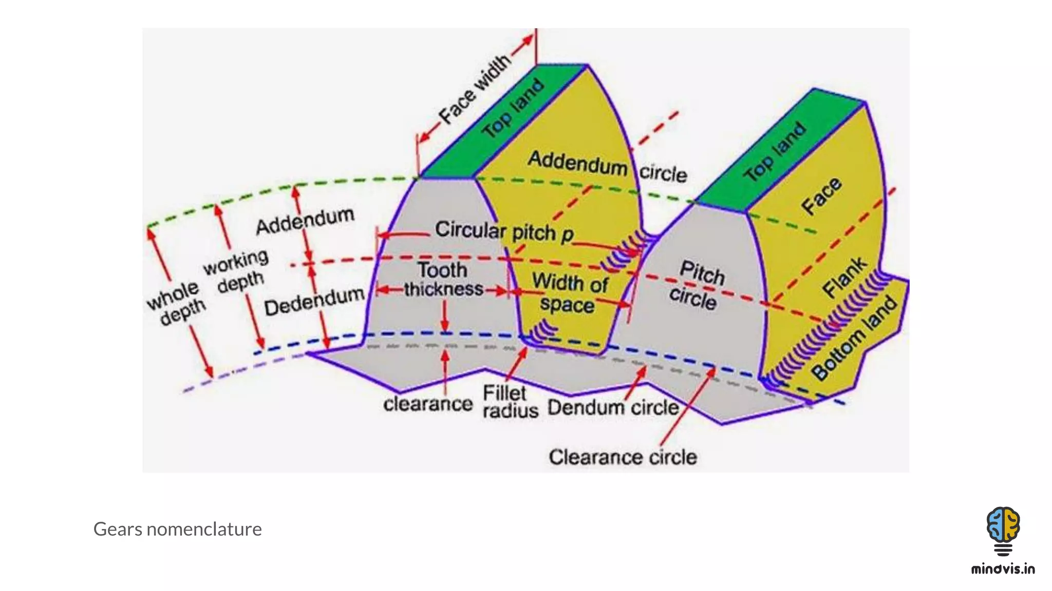
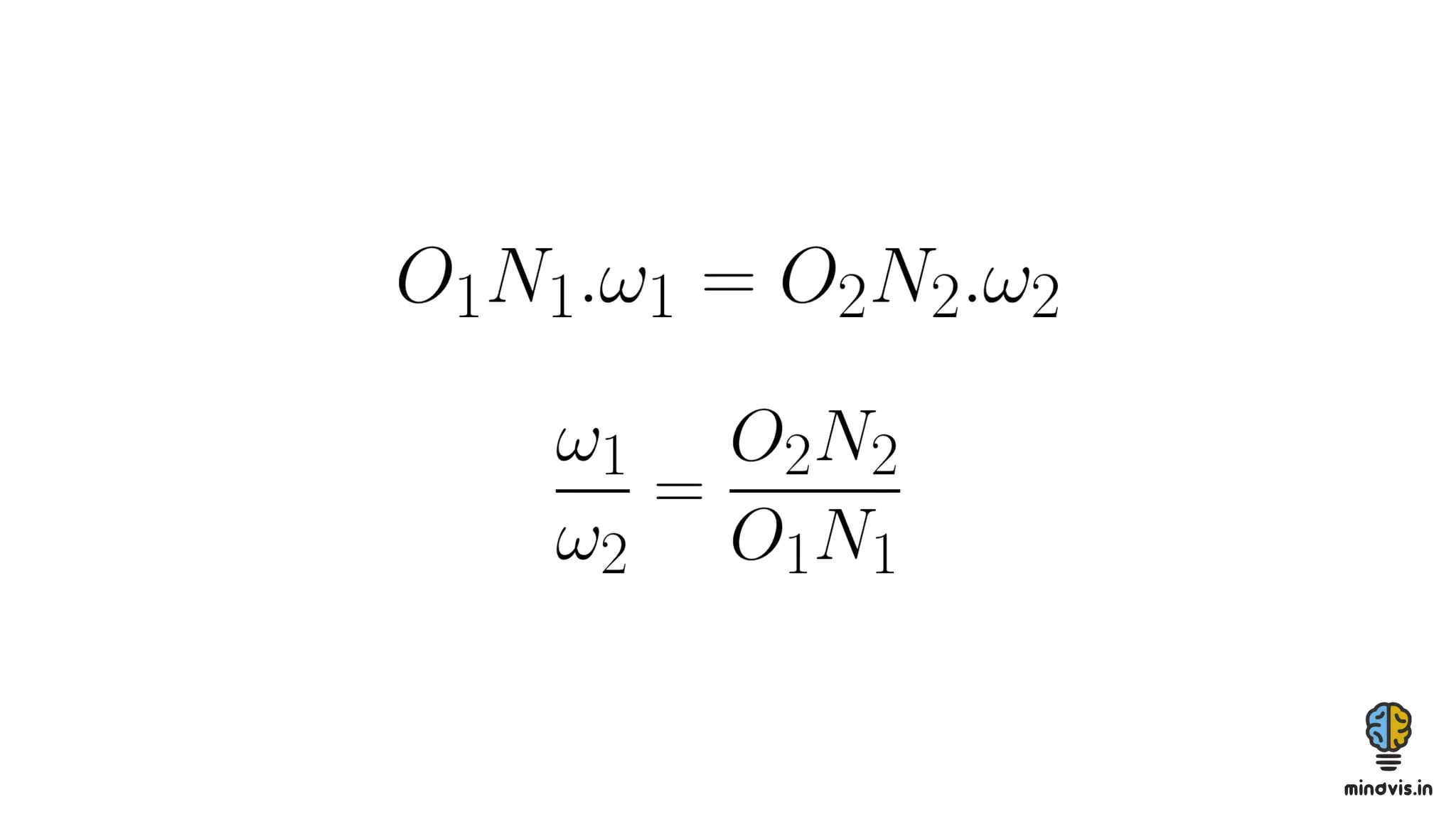


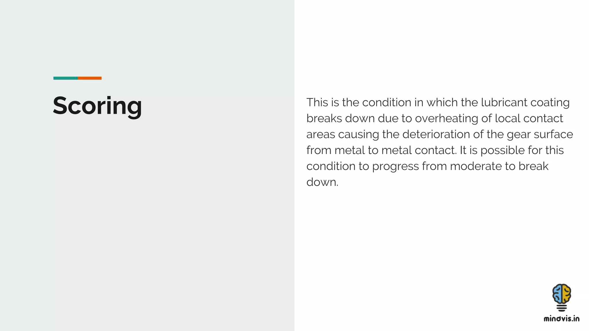


The document discusses the theory of gears, including their functions, classifications, and terminology, as well as the fundamental laws of gearing and tooth profiles such as involute and cycloidal. It also covers the significance of pressure angles in gear design and troubleshooting common gear issues like pitting, scoring, and spalling. The document serves as a comprehensive guide for understanding gears and their operational principles in machinery.


