Gears
•Download as DOCX, PDF•
0 likes•64 views

Gears BY Azlan Ali shah BSc Mechanical GCT Peshawar

Recommended
More Related Content
What's hot
What's hot (20)
Similar to Gears
Similar to Gears (20)
Recently uploaded
Recently uploaded (20)
Gears
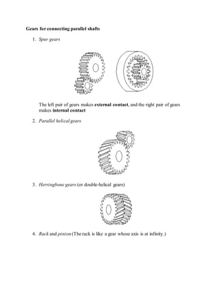
- 1. Gears for connecting parallel shafts 1. Spur gears The left pair of gears makes external contact, and the right pair of gears makes internal contact 2. Parallel helical gears 3. Herringbone gears (or double-helical gears) 4. Rack and pinion (The rack is like a gear whose axis is at infinity.)
- 2. Gears for connecting intersecting shafts 1. Straight bevel gears 2. Spiral bevel gears Neither parallel nor intersecting shafts 1. Crossed-helical gears 2. Hypoid gears 3. Worm and wormgear
- 3. 7.2 Gear-Tooth Action 7.2.1 Fundamental Law of Gear-Tooth Action Figure 7-2 shows two mating gear teeth, in which Tooth profile 1 drives tooth profile 2 by acting at the instantaneous contact point K. N1N2 is the common normal of the two profiles. N1 is the foot of the perpendicular from O1 to N1N2 N2 is the foot of the perpendicular from O2 to N1N2. Figure 7-2 Two gearing tooth profiles
- 4. Although the two profiles have different velocities V1 and V2 at point K, their velocities along N1N2 are equal in both magnitude and direction. Otherwise the two tooth profiles would separate from each other. Therefore, we have (7-1) or (7-2) We notice that the intersection of the tangency N1N2 and the line of center O1O2 is point P, and (7-3) Thus, the relationship between the angular velocities of the driving gear to the driven gear, or velocity ratio, of a pair of mating teeth is (7-4) Point P is very important to the velocity ratio, and it is called the pitch point. Pitch point divides the line between the line of centers and its position decides the velocity ratio of the two teeth. The above expression is the fundamental law of gear-tooth action. 7.2.2 Constant Velocity Ratio For a constant velocity ratio, the position of P should remain unchanged. In this case, the motion transmission between two gears is equivalent to the motion transmission between two imagined slipless cylinders with radius R1 and R2 or diameter D1 and D2. We can get two circles whose centers are at O1 and O2, and through pitch point P. These two circle are termed pitch circles. The velocity ratio is equal to the inverse ratio of the diameters of pitch circles. This is the fundamental law of gear-tooth action.
- 5. The fundamental law of gear-tooth action may now also be stated as follow (for gears with fixed center distance) (Ham 58): The common normal to the tooth profiles at the point of contact must always pass through a fixed point (the pitch point) on the line of centers (to get a constant velocity ration). 7.2.3 Conjugate Profiles To obtain the expected velocity ratio of two tooth profiles, the normal line of their profiles must pass through the corresponding pitch point, which is decided by the velocity ratio. The two profiles which satisfy this requirement are called conjugate profiles. Sometimes, we simply termed the tooth profiles which satisfy the fundamental law of gear-tooth action the conjugate profiles. Although many tooth shapes are possible for which a mating tooth could be designed to satisfy the fundamental law, only two are in general use: the cycloidal and involute profiles. The involute has important advantages -- it is easy to manufacture and the center distance between a pair of involute gears can be varied without changing the velocity ratio. Thus close tolerances between shaft locations are not required when using the involute profile. The most commonly used conjugate tooth curve is the involute curve (Erdman & Sandor 84). 7.3 Involute Curve The following examples are involute spur gears. We use the word involute because the contour of gear teeth curves inward. Gears have many terminologies, parameters and principles. One of the important concepts is the velocity ratio, which is the ratio of the rotary velocity of the driver gear to that of the driven gears.
- 6. The SimDesign file for these gears is simdesign/gear15.30.sim. The number of teeth in these gears are 15 and 30, respectively. If the 15-tooth gear is the driving gear and the 30-teeth gear is the driven gear, their velocity ratio is 2. Other examples of gears are in simdesign/gear10.30.sim and simdesign/gear20.30.sim 7.3.1 Generation of the Involute Curve Figure 7-3 Involute curve The curve most commonly used for gear-tooth profiles is the involute of a circle. This involute curve is the path traced by a point on a line as the line rolls without slipping on the circumference of a circle. It may also be defined as a path traced by the end of a string which is originally wrapped on a circle when the string is unwrapped from the circle. The circle from which the involute is derived is called the base circle. In Figure 7-3, let line MN roll in the counterclockwise direction on the circumference of a circle without slipping. When the line has reached the position M'N', its original point of tangent A has reached the position K, having traced the involute curve AK during the motion. As the motion continues, the point A will trace the involute curve AKC. 7.3.2 Properties of Involute Curves 1. The distance BK is equal to the arc AB, because link MN rolls without slipping on the circle. 2. For any instant, the instantaneous center of the motion of the line is its point of tangent with the circle. Note: We have not defined the term instantaneous center previously. The instantaneous center or instant center is defined in two ways (Bradford & Guillet 43): 1. When two bodies have planar relative motion, the instant center is a point on one body about which the other rotates at the instant considered.
- 7. 2. When two bodies have planar relative motion, the instant center is the point at which the bodies are relatively at rest at the instant considered. 3. The normal at any point of an involute is tangent to the base circle. Because of the property (2) of the involute curve, the motion of the point that is tracing the involute is perpendicular to the line at any instant, and hence the curve traced will also be perpendicular to the line at any instant. 4. There is no involute curve within the base circle. 7.4 Terminology for Spur Gears Figure 7-4 shows some of the terms for gears. Figure 7-4 Spur Gear In the following section, we define many of the terms used in the analysis of spur gears. Some of the terminology has been defined previously but we include them here for completeness. (See (Ham 58) for more details.) Pitch surface : The surface of the imaginary rolling cylinder (cone, etc.) that the toothed gear may be considered to replace. Pitch circle: A right section of the pitch surface. Addendum circle: A circle bounding the ends of the teeth, in a right section of the gear. Root (or dedendum) circle: The circle bounding the spaces between the teeth, in a right section of the gear. Addendum: The radial distance between the pitch circle and the addendum circle. Dedendum: The radial distance between the pitch circle and the root circle.
- 8. Clearance: The difference between the dedendum of one gear and the addendum of the mating gear. Face of a tooth:That part of the tooth surface lying outside the pitch surface. Flank of a tooth:The part of the tooth surface lying inside the pitch surface. Circular thickness (also called the tooth thickness) : The thickness of the tooth measured on the pitch circle. It is the length of an arc and not the length of a straight line. Tooth space: The distance between adjacent teeth measured on the pitch circle. Backlash: The difference between the circle thickness of one gear and the tooth space of the mating gear. Circular pitch p: The width of a tooth and a space, measured on the pitch circle. Diametral pitch P: The number of teeth of a gear per inch of its pitch diameter. A toothed gear must have an integral number of teeth. The circular pitch, therefore, equals the pitch circumference divided by the number of teeth. The diametral pitch is, by definition, the number of teeth divided by the pitch diameter. That is, (7-5) and (7-6) Hence (7-7) where p = circular pitch P = diametral pitch N = number of teeth D = pitch diameter
- 9. That is, the product of the diametral pitch and the circular pitch equals . Module m: Pitch diameter divided by number of teeth. The pitch diameter is usually specified in inches or millimeters; in the former case the module is the inverse of diametral pitch. Fillet : The small radius that connects the profile of a tooth to the root circle. Pinion: The smaller of any pair of mating gears. The larger of the pair is called simply the gear. Velocity ratio: The ratio of the number of revolutions of the driving (or input) gear to the number of revolutions of the driven (or output) gear, in a unit of time. Pitch point: The point of tangency of the pitch circles of a pair of mating gears. Common tangent: The line tangent to the pitch circle at the pitch point. Line of action: A line normal to a pair of mating tooth profiles at their point of contact. Path of contact: The path traced by the contact point of a pair of tooth profiles. Pressure angle : The angle between the common normal at the point of tooth contact and the common tangent to the pitch circles. It is also the angle between the line of action and the common tangent. Base circle :An imaginary circle used in involute gearing to generate the involutes that form the tooth profiles. Table 7-1 lists the standard tooth system for spur gears. (Shigley & Uicker 80)