The ME300 Summer Practice Report by Samet Baykul provides an overview of the Note Elevator company, detailing its organizational structure, manufacturing processes, and specific projects undertaken during an internship. The report outlines the technical and operational aspects of the elevator manufacturing process, including various techniques such as shearing, drilling, and welding. It highlights the company's focus on delivering customized elevator solutions and the challenges faced in manufacturing efficiency and quality control.


![ii
ME 300 Summer Practice Report October 19, 2016
References
Asansör Sektörü Raporu (Sektörel Raporlar ve Analizler Serisi) [2]. (2015). Retrieved
from http://aysad.org.tr/Document/NoticeDocumentGalery/2015-2 Asansor-
sektoru-raporu-20-2112015133019.pdf
Black, J.T., & Kohser R.A. (2008). Materials & Processes in Manufacturing. U.S: Wiley.
Otis Elevator. Elevator 101 Introduction to Elevator Technology Technology. Retrieved
October 12, 2016, from Mass,
http://www.mass.gov/anf/docs/dcam/mafma/tutorials/elevator-101.pdf
Hypertherm HPR260XD Consumable Parts
https://www.weldersupply.com/C/202/HyperthermHPR260XDConsumables?page=3
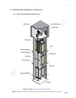
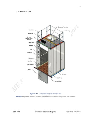
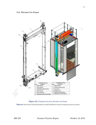
Shaun. (2013, January 29). Basic elevator components - part One. Retrieved October 12,
2016, from electrical-knowhow, http://www.electrical-
knowhow.com/2012/04/basic-elevator-components-part-one.html](https://image.slidesharecdn.com/2016-190801205111/85/Note-Elevator-Summer-Practice-Report-67-320.jpg)