Downloaded 677 times


![SP : 34(!3&T)-1987
SE‘CTION 1
STEEL FOR REINFORCEMENT
1.0 Reinforcing bars/ wires for concrete
reinforcement shall be any of the following
conforming to accepted standards:
b)
4
Mild steel and medium tensile steel bars
[IS : 432 (Part I)-1982 S cification for
mild steel and medium tensi e steel bars andf”
hard-drawn steel wire for concrete rein-
forcement : Part I Mild steel and medium
tensile steel bars (third revision)].
High strength deformed steel bars/ wires
[IS : 1786-1985 Specification for high
strength deformed steel bars and
wires for concrete reinforcement
(third revision).
Hard-drawn steel wire fabric [IS : 1566-1982
Specification for hard-drawn steel wire
fabric for concrete reinforcement (second
re+ision)].
The requirements for manufacture and supply
of different types of steel reinforcement are briefly
highlighted in 1.1 to 13.43.
NOTE- Different types of reinforcing bars, such as plain
bars and deformed bars of various grades, say Fe415
(N/mm,) and Fe500 (N/mm*), should not be used side by
side as this practice will lead to confusion and error at site.
Howwcr.secondaryrcinforamcnt such as ties and stirrups,
may be of’mild steel throughout even though the main steel
may be of high strength deformed bars.
1.1 Mild Steel and Medium Tensile Steel Bars
11.1 Reinforcement supplied shall be classi-
fied into the following types:
a) mild steel bars, and
b) medium tensile steel bars.
1.1.1.1 Mild steel bars shall be supplied in
the following two grades:
a) mild steel ba;s, Grade 1; and
b) mild steel bars, Grade II.
Non!- In all cases where the design seismic coefficient
[src IS : 1893-1984 Critetja for earthquake resistant desir
of structures ~ourrh rrvisiun)] chosenfor the structure is0. 3
or more (which include earthquake zanes IV and V) and for
8tructures subjected to dynamic loading. use of
Grade II bars is not recommended.
1.1.2 Physical/ Mechanical Properties - The
requirements for physical/ mechanical properties
of mild steel and medium tensile steel bars are
given in Table I. 1.
1.1.3 Tolerance - The rolling and cutting
tolerances shall be as specified in 1.1.3.1 and
1.1.3.2.
1.1.3.1 Bars in straight lengths
a) The tolerance on diameter shall be as follows:
Diameter Tolerance,
A
r Over Up to and’
percent
including
mm mm mm
- 25 kO.5
25 35 kO.6
35 50 kO.8
50 80 k1.0
80 100 f1.3
100 - + 1.6
b) The permissible ovality measured as the
difference between the maximum and mini-
mum diameter shall be 75 percent of the
tolerance (k) specified on diameter.
c) The tolerance on weight per m length shall
be as follows:
Diameter Tolerance,
’ Over
A
Up to and’
percent
including
mm mm
- IO f7
10 16 +5
16 - f3
1J.3.2 Coiled bars
a) The tolerance on diameter shall be kO.5 mm
for diameters up to and including I2 mm.
b) The difference between the maximum and
minimum diameter at any cross-section shall
not exceed 0.65 IW:.
NATE- No weight tokrana is specified for coikd ban.
1.2 High Strength Deformed Steel Bars
13.1 Deformed steel bars/ wires for use as
reinforcement in concrete shall be in the following
three grades:
a) Fkl5,
b) Fe500, and
c) Fe550.
HANDBOOK ON CONCRETE REINFORCEMENT AND DETAILING](https://image.slidesharecdn.com/sp34-strdetailing-130507020321-phpapp01/85/Sp34-str-detailing-9-320.jpg)


![SP : 34(S&T)-1987
3.5 Marks for Parts of Buildings (that is, column for
3.5.1 Marks are used to designate the different
storey 2, or column
structural members of a structure. Different
between floor 2
structural members of a struCture shall be marked
and 3).
using symbols, abbreviations and notati&s 3.5.4 Beams, slabs and lintels, and tie beams
indicated in succeeding clauses and in the manner shall be consecutively numbered from left-hand
indicated in other clauses. top corner (see Fig. 3.3A).
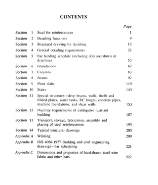
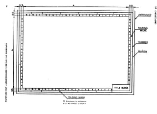
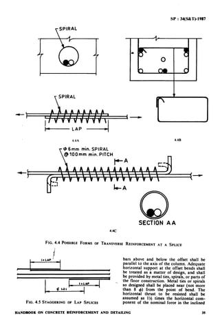
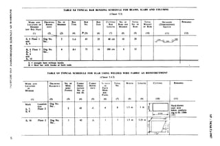
3.5.2 A key framing plan shall be prepared to
ai convenient scale and the t AOaxes marked one
side with alphabets A, B, C, etc. and the other
with numbers (see Fig. 3.3). Normally with
rectangular pattern, the same key framing plan
may be used for all floors. However, if
arrangement of beams vary for different floors a
separate key framing plan with grid arrangement
and areas may be used for each of the floor. The
floors shall be .specified in accordance with the
requirements of IS : 2332-1973 ‘Specifications for
nomenclature of floors and storeys’ and
abbreviations BT and MZ shall be used for
basement and mezzanine, respectively, for
example:
B-I-
MZ
Floor I
‘Basement
Mezzanine
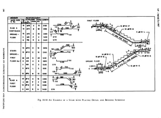
3.5.5 If longitudinal section of the beam is
shown, the grid of the column or number of the
column supporting the beam is being detailed
shall be as indicated as in fig. 3.3B and, if
possibie, inset on the drawing showing the key
framing plan. On the other hand if a beam
schedule is included, a table [see Fig. 3.3C] may
be prepared and inset on the drawing showing the
key framing plan [see Fig. 3.3A].
3.5.5.1 Beams or slabs that are similar may
be given in the same number.
3.5.6 Walls - Marking of walls shall be made
in the serial order starting from top left corner of
plan and proceeding towards the right, followed
by subsequent rows in order. Longitudinal walls
and cross-walls shall be marked separately (see
Fi .
f!
3.4) and identified in the drawing with
re erence to the serial number of the floor.
Floor 2
Example
3.5.3 Columns - Columns and foundations
2 WL - I Longitudinal wall No. 1
shall be specified by grid arrangement giving
at floor 2 (between
reference to the floor. for examole Isee Fie. 3.3Aj.
floor 2 and 3).
FG Col El
. .
Footing for Column El
4 WX - 3 Cross-wall No. 3 at
floor 4 (between floor 4
Co1 2EI Column El at floor 2 and 5).
33
n
FIG. 3.3 TYPICAL ARRANCXNENT FORTHE KEY FRAMING PLAN AND MARKING DIFFERENTSTRUCTURAL
MEMBERS(Continued)
24 HANDBOOK ON CONCRETE REINFORCEMENT AND DETAHJNG](https://image.slidesharecdn.com/sp34-strdetailing-130507020321-phpapp01/85/Sp34-str-detailing-30-320.jpg)


![sP : 34fM~)-1987
which the tension reinforcement is not parallel to
the compression face.
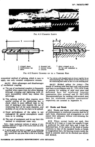
4.4 Reinforcement Splicing - Splicing is
required to transfer force from one bar -t,o
another. Methods of splicing include lapping (see
4.4.2), welding (see Appendix A) and mechanical
means (see -4.4.3).
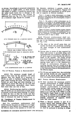
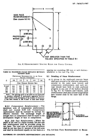
4.4.1 Where splices are provided for
continuity in the reinforcing bars (tension bars in
beams), they shall be as far as possible away from
the sections of ,maximum stress and be staggered.
It is recommended that splice in flexural members
should not be at sections where the bending
moment is more thaa 50 percent of the moment of
resistance of the section. Not more than half the
bars shall & spliced at a section.
Where more than one half of the bars are
spll’ced at a section or where splices are made at
points of maximum stress, special precautions
shall be taken, such as increasing the length of lap
and/or using spirals or closely spaced stirrups
around the length of /the splice.
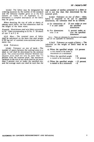
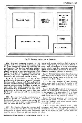
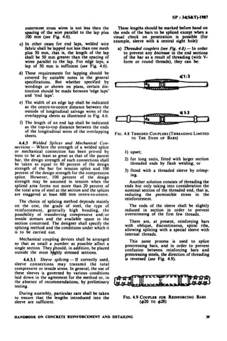
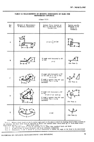
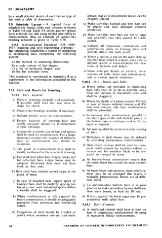
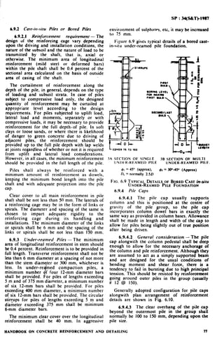
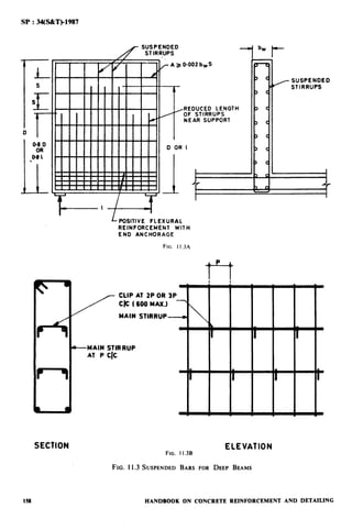
NATE l -The stirru s provided should be able to resist a
tension equal to the fu I tenstle force in the lapped bars andP
should be provided in the outer one-third of the lap length
at both etids with at least three stirrups on either side (see
Fig. 4.3). In case of thick bars (say 4 > 28 mm), lap splices
shoutd be completely enclosed by transverse reinforcement,
for example. in the form of small compact stirrups or spirats
[see Fig. 4.4 (A and B)].
NOTE 2 -Careful detailing is necessary when
reinforcements are to be spliced. Therefore location and
details of splices should be determined at the design stage
itself and indicated in the drawing. Preferably splicing
details should not be left to be decided at the site of
construction.
44.2 Lap Splices
a) Diameter of bars for lap splicing - Lap
splices shall not be used for bars larger than
36 mm. For larger diameters, bars may be
welded (see Appendix A).
34
b)
cl
In cases where welding is not practicable,
lapping of bars larger than 36 mm may be
permitted, in which case additikal spirals
should be provided around the lapped bars
(see Fig. 4.4A).
Staggering of lap splices - Lap splices
shall bc considered as staggered if the
centre-toxentre distance of the splices is not
less than 1.3 times the lap length (see Fig. 4.5)
calculated as given in (c) below. Bars
could be lapped vertically one above the
other or horizontally, depending upon the
space requirement.
Lup length in tension - Lap length includ-
ing anchorage value of hooks in flexural
tension shall be h or 30 4 whichever is
greater and for direct tension 2 Ld or 30 4
whichever is greater. The straight length
of the lap shall not be less than 15 4 or
200 mm, whichever is greater (see Fig. 4.6).
where
I,,, = development length
NOTE- Splices in direct tension members shall be
enclosed in spirals made of bars not less than 6 mm in dia-
meter with pitch not more than IO cm. Hooks/bends shall
bc provided at the end of bars in tension members (see
Fig. 4.4C).
d)
e)
Lap length in compression --The lap
length in compression shall be equal to the
development length in compression calcula-
ted as in 4.2.2 (see Tables 4.2, 4.3 and 4.4),
but not less than 24 4.
Requirement of splice in a column - In
columns where longitudinal bars are offset
at a splice, the slope of the inclined portion
of the bar with the axis of the column shall
not exceed I in 6. and the portions of the
1
I
-5-
L
4 L-LAP
-P-’
c
FIG. 4.3 TRANSVERSE REINFORCEMENT AT A SPLICE
HANDBOOB ON CONCRETE REINFORCEMENT AND DETAILING](https://image.slidesharecdn.com/sp34-strdetailing-130507020321-phpapp01/85/Sp34-str-detailing-40-320.jpg)


![SP : 34(S&T)-198’7
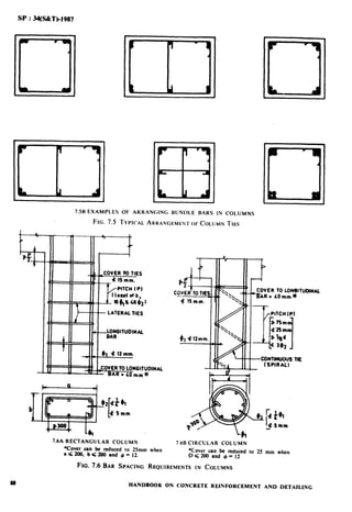
9.4.1 The slabs are considered as divided in
each direction int:o middle strips and edge strips
as shown in Fig. !9.3, the middle strip being three-
quarters of the width and each edge strip one-
eighth of the width.
9.4.2 The tension reinforcement provided at
mid-span in the imiddle strip shall extend in the
lower part of the slab to within 0.25 1 of a
continuous edge, or 0.15 I of a discontinuous
edge.
9.4.3 Over the continuous edges of a middle
strip, the n.ension reinforcement shall extend in the
upper p&n;of the ,slab a distance of 0.15 1from the
support, and at least 50 percent shall extend a
distance rif 0.30 1.
9.4.4 ,4t a discontinuous edge, negative
moments may arise. They depend on the fixity at
the cedge of the slab but, in general, tension
reinforcement equal to 50 percent of that
provided at mid-span extending 0.1 I into the span
will be sufficient.
9.43 Reinforcement in edge strip parallel to
the edge, shall comply with the minimum
reinforcement requirement (9.1) and the
requirements for torsion in 9.4.6. to 9.4.6.2.
9.4.6 torsional Reinforcement - Torsional
reinforcement shall be provided at any corner
where the slab is simply supported on both edges
meeting at that corner and is prevented from
lifting unless the consequences of cracking are
negligible. It sh;all consist of top and bottom
reinforcement, each with layer of bars placed
parallel t3 the sides of the slab and extending
from the edges a minimum distance of one-fifth of
the shorter span. The area of reinforcement per
unit widt’h in ea’ch of these four layers shall be
three-quarters of the ~area required for the
maximum mid-span moment per unit width in the
slab (see Fig. 9.4A).
9.4.6.1 Torsional reinforcement equal to
half that ‘described in 9.4.6 shall be provided at a
corner cointained by edges over only one of which
the slab is’continuous. (see Fig. 9.4B.)
9.4.6.2 Torsional reinforcement need not be
provided at any corner contained by edges over
both of which t.he slab is continuous.
9.4.7 .A slab shall be treated as spanning one
way (in the shorter direction) when ratio of
effective span in the longer direction to the
effective :span in. the shorter direction is greater
than 2.
9.4.8 Figure ‘9.5illustrates curtailment of bars
in a restrained slab spanning in two directions
based on the above rules using straight bars or
bent-up bars.
9.4.9 Re-entrant Corners- Diagonal rem-
forcement shall be placed at all re-&trant corners
to keep crack widths within limits (see Fig. 9.6).
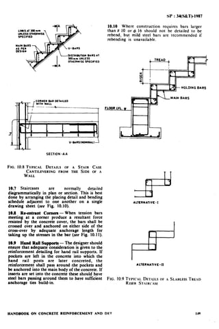
9.5 Cantilever Slabs-The main reinforcement
shall be placed in the top of cantilever slab
extending to sufficient length over the support
and back into the normal span.Ttie method of
curtailment shall conform to the requirements
specified in Section 4.
Support to the top steel of cantilever slabs at
spacings -(for stools and chairs) should preferably
be specified in the detailing drawing. The bending
of the main bars should be such that they
contribute to the supporting of the steel, that is,
bars that extend to the end should have vertical
bends, with a fixing bar at the bend.
The secondary steel at right angles to fhe
support may be designed and -detailed to carry
construction loading in the propped condition, if
necessary.
The deflection in cantilever slabs can be
reduced by the addition of compression steel at
the bottom. This would also be . helpful in
counteracting possible reversal of bending
moments.
9.5.1 The simplified curtailment rules
illustrated in Fig. 9.7 may be used for cantilever
slabs when they are designed for predominantly
uniformly distributed loads.
9.5.2 Tie Backs and Counter Masses to
Cantilevers
9.5.2.1 Cantilever at the bottom of
beams- Ensure, when a cantilever is at the
bottom of a beam, the design of the stirrups in the
beam provides for moment, shear, hanging
tension and, if necessary, torsion. If possible,
provide in the detailing of this steel for placing of
the beam steel without the necessity of. the
threading of the main beam steel through the
cantilever anchorage loops. The details should
conform to the basic principles a plicable to
opening corner in retaining walls ans the beams.
Figure 9.8 provides three alternative methods of
anchoring bars in supporting beams.
NOTE- Note the special difficulty induced by bent-up
bars in the beam steel:
a) Curtailed bars going to the back of a beam may drift _
out of position during casting of concrete.
b) Hairpin type bars should be related to the horizontal
stirrup spacing, and this may cause difficulties.
c) Loops of 270° are difficult to bend and place in
position.
9.5.2.2 Cantilever at the top of bedms-
Where the weathering course is 30 mm -or less,
crank the-bars at a slope not exceeding 1 in 6 [see
Fig. ~9.9(A)]. Ensure that the combination of top
bars and stirrups is such as to provide the
required restraint. Note that if a bar is laced over
and under the beam bars, it is fully restrained
provided that the beam top bars are heavy enough
and a stirrup is within 50 mm of such bar- If the
bar is not so laced, detail the steel to ensure the
anchorage against bursting (see Fig. 9.9).
124 HANDBOOK ON CONCRETE REINFORCEMENT AND DETAILING](https://image.slidesharecdn.com/sp34-strdetailing-130507020321-phpapp01/85/Sp34-str-detailing-130-320.jpg)


![SP : 34(S%T)_1987
I,100
r?ncH SL*
Il.27A SINGLE LAYER
SECTION AA
SECTION AA
DETAIL AT
AT SUITABLE
INTERVALS TO KEEP
THE CAGE IN POSITION
II.278 DOUBLE LAYER
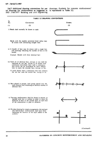
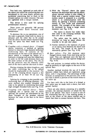
FIG. 11.27TYPICAL DETAILS OF PIPES
11.8.2 Foundations forRotary Type Machines
of Low Frequency [IS : 2974(Part 4)1979] -The
base slab, 70 kg/m3 of concrete for columns and
amount of minimum reinforcement for block
90 kg/m3 of concrete for top slab.
foundation shall be 25 kg/m-’ of concrete. The
amount of minimum reinforcement for frame Stirrups suitably spaced shall be provided to tie
foundations shall be 40 kg/m3 of concrete for together the main longitudinal bars.
HANDBOOK ON CONCRETE REINFORCEMENT AND DETAILING 179](https://image.slidesharecdn.com/sp34-strdetailing-130507020321-phpapp01/85/Sp34-str-detailing-185-320.jpg)
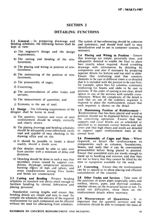
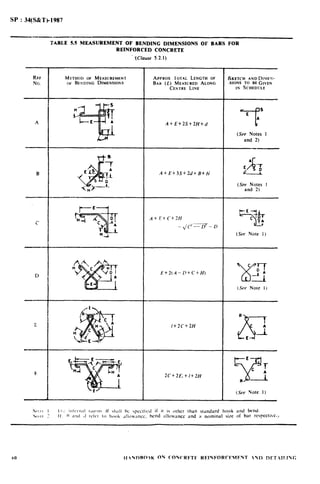
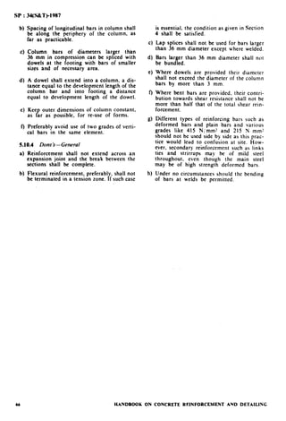
![SP : 34(S&T)-1987
CUT-IN
L FOUNOATION BLOCK
FIG. II.28 TYPICAL REINFORCEMENTDETAIL
The minimum diameter of the mild steel bars
shall be 12 mm and the maximum spacing shall be
200 mm.
The concrete cover for protection of
reinforcement shall be 75 mm at the bottom, 50
mm on sides and 40 mm at the top.
Typical arrangement of reinforcements are
shown in Fig. I 1.29 to I I .31.
11.8.3 Foundations for Reciprocating Type
Machines [IS : 2974 (Part 1)1982].
11.8.3.1 Minimum reinforcement in block
foundations - Minimum remforcement in the
concrete block shall be not less than 25 kg/mJ.
For machines requiring special design
considerations of foundations, like machines
pumping explosive gases, the reinforcement shall
be not less than 40 kg/ m3.
The minimum reinforcement in the block shall
usually consist of 12 mm bars spaced at 2001250
mm centre-tocentre extending both vertically and
horizontally near all the faces of the foundation
block.
11.8.3.2 The following points shall be
considered while arranging the reinforcements:
a)
W
cl
4
A
The ends of mild steel (if used) shall always
be hooked irrespective of whether they are
designed for, tension or compression;
Reinforcement shall be used at all faces;
If the height of foundation block exceeds
one metre, shrinkage reinforcement shall be
placed at suitable spacing jn all three direc-
tions; and
Reinforcement shall be provided around all
pits and openings and shall be equivalent to
0.50 to 0.75 percent of the cross-sectional
area of the opening.
typical arrangement of reinforcement in a
reciprocating machine foundation is shown in
Fig. 11.32.
180 HANDBOOK
11.8.4 Foundations for Rotary Type
Machines (Medium and High Frequency)
g.SiiTn74 (Part 3)_1975 Code of Practice for
and Construction of Machine
Foundations: Part 3 Foundation for Rotary Type
of Machines (Medium and High Frequency)
(First Revision)].
11.8.4.1 The vertical reinforcing bars of the
column shall have sufficient embedment in the
base slab to deveiop the required stresses.
11.8.4.2 All units of foundation shall be
provided with double reinforcement.
Reinforcements shall be provided along the other
two sides of cross-sections of beams and columns,
even if they are not required by design
calculations so that symmetric reinforcement will
be ensured in opposite sides.
11.8.4.3 The amount of minimum rein-
forcement for major structures components of the
framework shall be as follows:
a) Base slab 40 kg/m3 of concrete
b) Columns 70 kg/m3 of concrete
c) Top table 90 kg/m3 of concrete
(slab and beam)
Typical arrangement of reinforcement is shown
in Fig. 11.33.
11.8.4.4 Stirrups suitably spaced shall be
provided to account for the entire shear in the
foundation elements.
11.8.4.5 The minimum diameter of
longitudinal steel for beams and columns should
be selected so that the maximum spacing of these
bars shall not be more than 150 mm.
11.8.4.6 Reinforcement cover - Unless
specified otherwise, the concrete cover for
reinforcement protection shall be as follows:
a) Base slab 100 mm for top,
bottom and sides
b) Columns and 50 mm on sides
pedestals
c) Beams 40 mm on sides
11.8.4.7 Minimum
B
rade of concrete for
foundation shall be not ess than M20.
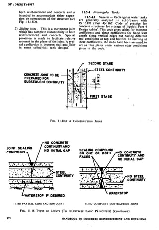
11.8.4.8 Construction joints - The base
slab shall be cast in a single pour. A properly
designed construction joint shall be provided
between the base slab and the columns.
Wherever intermediate decks exist and
construction joints are to be provided, the
subsequent set of construction joints shall be
provided at the top of each such intermediate
deck:
In case there is no intermediate deck,
continuous concreting shall be done for the
columns and the upper deck.
ON CONCRETE REINFORCEMENT AND DETAILING](https://image.slidesharecdn.com/sp34-strdetailing-130507020321-phpapp01/85/Sp34-str-detailing-186-320.jpg)


![SP : 34(S&Tbl987
SECTION 12
DUCTILITY REQUIREMENTS OF EARTHQUAKE RESISTANT BUILDINGS
12.0 General -The primary members of struc-
ture such as beams and columns are subjected to
stress reversals from earthquake loads. The
reinforcement provided shall cater to the needs of
reversal of moments in beams and columns, and
at their junctions.
Earthquake motion often induces forces large
enough to cause inelastic deformations in the
structure. If the structure is brittle, sudden failure
could occur. But if the structure is made to
behave ductile, it will be able to sustain the
earthquake effects better with some deflection
(Am) larger than the yield deflection (Ay) by
absorption of energ . Therefore, besides the
design for strength orythe frame, ductility is also
required as an essential element for safety from
sudden collapse during severe shocks. It has also
been observed during past earthquakes that
structures designed and built for low seismic
coefficients survived severe earthquakes with little
damage because of energy absorption in plastic
deformations.
In zones where risk of major damage from
earthquake loads is possible, ductile frame is
reqmred m accordance with IS : 4326-1976 ‘Code
of practice for earthquake resistant design and
construction of buildings (first revision)‘. These
provisions are generally applicable to all seismic
zones but its importance is greater where severe
earthquake loadings will become much more
significant than other concurrent loads.
Accordingly the Code makes it obligatory that in
all cases where the design seismic coefficient [see
IS : 1893-1976 ‘Criteria for earthquake resistant
design of structures (third revision)‘] is 0.05 or
more (which invariably includes zones IV and V)
ductility provisions specified in IS : 43261976
shall be adopted. The ductility requirements will
be deemed to be satisfied if the conditions given in
the following clauses are achieved.
12.1 Flexural Members
12.1.1 The to
P
as well as bottom steel
reinforcement sha 1 consist of at least two bars
each throughout the length of the member, and
the steel ratio p on either face (both on
compression and tension face) shall not be less
than as given below:
For M 15 concrete and plain mild steel bars,
pmin= 0.003 5
For other concrete and steel reinforcement,ptii,
= 0.06 FJ F,
where
p = As/M,
F, = 28day cube crushing strength of concrete,
F, = yield stress of reinforcing steel,
A, = area of steel on a face,
b = breadth of beam web, and
d = effective depth of section.
12.1.2 The maximum tensile steel ratio on any
face at any section shall not exceed the following
For M 15 concrete and plain mild steel bars,
pmax = PC + 0.011
For other concrete and mild steel reinfora-
ment, pm, = pc + 0.19 FJF,
For concrete’ reinforced with coldworked
deformed bars, prmX= ps + 0.15 F,/ F,
where
PC = actual steel ratio on the compression face.
12.1.3 When a beam frames into a column,
both the top and bottom bars of the beam shall be
anchored into the column so as to .develop their
full tensile strength in bond beyond the section of
the beam at the face of the column. Where beams
exist on both sides of the column, both face bars
of beams shall be taken continuously through the
column.
NOTE- To avoid congestion of steel in a column in which
the beam frames on one side only, it will be preferable to use
U-type of bars spliced outside the column instead of
anchoring the bars in the column.
Figure 12.1 shows ,the typical detail for a beam
framing into column from one side -or two sides.
Such an arrangement will ensure a ductile
junction and provide adequate anchorage of beam
reinforcement into columns. Top and bottom
longitudinal steel for beams framing into both
sides of column should extend through the
column without splicing.
12.1.4 The tensile steel bars shall not be
spliced at sections of maximum tension and the
splice shall be contained within at least two closed
stirrups (see Fig. 12.2).
12.1.5 The web reinforcement in the form of
vertical stirrups shall be provided so as to develop
the vertical shears resulting from all ultimate
vertical loads acting on the beam plus those which
HANDBOOKON CONCRETEREINFORCEMENTAND DETAILING 189](https://image.slidesharecdn.com/sp34-strdetailing-130507020321-phpapp01/85/Sp34-str-detailing-195-320.jpg)


![SP : 34(S&T)-1987
INCLINATION
FIG. A-l EDGE PREPARATION OF INCLINED BARS
recommended before welding is commenced on
second side. The root run and one further run
should be deposited on the first side. Where
possible the back chipping and root run on the
second side should then follow and the remaining
runs should preferably be deposited on alternate
sides of the joint to assist in controlling distortion.
A-1.3.1.7 Indirect butt splices may be made
by weldirig bars to splice plate, angle, sleeve, etc.
using single or double fillet welds as shown in
Fig. A-2. The splice member used. that is, plate,
angle, bar, sleeve, etc. should have a cross-
sectional area such that its strength is at least 5
percent higher than the strength of the bars being
welded. The bars shall not be eccentric by more
than 3 percent of the bars joined. The angles when
used may be flattened to suit for welding higher
size bars.
A-1.3.2 Lap Welding of Mild Step1 Bars
A-1-.3.2.1 Edge preparation is not necessary
for lap welds. The length of bars to be welded
shou’ld be free from scale, dirt, grease, paint. rust
and contaminants.
A-1.3.2.2 The bars may be lap welded using
the details given in Fig. A-3. Detail given in Fig.
A-3(A) is used when the bars are in contact with
each others. If the bars are bent, the maximrlm
gap shall be 6 mm.
When the gap between bars is more than 6 mm
the joint should be made using a splice bar or
plate [set’ Fig. A-3 (A)]. The gap between the bal
and splice plate should not exceed 0.25 times the
diameter of the bar or 5 mm,whichever is less.
The area of the splice materiai shall be at least 5
percent more than the area of the higher size bar
being welded.
Some information regarding throat thickness
and reinforcement is given in Table A-2.
A-1.3.2.3 The dimensions of the fillet welds
(length and throat thickness) shall be capable of
developing the full strength of the bar. The
TABLE A-2 DLTAILS FOR LAP WELDED JOINTS
((‘hrsr A-1.3.2.2)
BAK DIAMI~H TIIIWAT GAP
TIIICKN’ESS HETWFFii
REINFOWCI~WNT
Min (AIVROS)
0, (2) (3)
mm mm mm
Up to 12 3 1.5
Over I? up to I6 3
Over 16 z 3
Non: I II 2,“) overhead weld is required. it
should be made prior to the flat welds.
Non: 2 If the bars are bent. the maximum gap should
MI exceed 6 mm.
eccentricity in the joint should be taken into
consideration in the design calculations.
A-1.3.3 Square Burr M’elds - Square butt
welds may be used for direct butt welding and
shall be made using hydrogen controlled
electrodes or the thermit welding process.
A-l.4 Selection of Welded Joints
A-1.4.1 Direct butt splices (Table A-I) and,
as a second choice indirect butt splices (see Fig.
A-I), should be specified for bars of diameter 20
mm and over in order to reduce effects of
eccentricity.
A-1.4.2 For bars of diameter up to 20 mm
indirect splicing (see Fig. A-l) may be used
although lap welds are normally adopted for such
bars.
A-I .4.3 Square Butt Welds - The bars may
he directly jointed with square butt welds provided
the welds are made using hydrogen controlled
electrodes or thermit welding process.
A-1.5 Location of Welded Joints - Welded
joints should be staggered in the length of the
212 HANDBOOK ON CONCRETE REINFORCEMENT AND DETAILING](https://image.slidesharecdn.com/sp34-strdetailing-130507020321-phpapp01/85/Sp34-str-detailing-218-320.jpg)


![SP : 34(S&T)-1987
APPENDIX B
(Chuse 59.1)
IS0 4066-1977 BUILDING AND CIVIL ENGINEERING DRAWINGS-BAR SCHEDULING*
B-O. INTRODUCTION
The purpose of this International Standard is to
ensure uniformity of practice in the scheduling of
steel bars for the reinforcement of concrete. To
establish a clear and unambiguous system for
scheduling, it is necessary to specify the method of
indicating dimensions to be used and the order in
which the information is given on the bar
schedule.
As the use of preferred shapes is considered to
be very advantageous both for simplifying design
and manufacture and for the use of covputers,
the opportunity has been taken to include a list of
preferred shapes and a coding system; the layout
of the bar schedule is based on the use of
preferred shapes.
B-l. SCOPE
This International Standard establishes a system
for the scheduling of reinforcing bars, and
comprises
- the method of indicating dimensions;
- a coding system for bar shapes;
- a list of preferred shapes;
- the bar schedule.
B-2. FlELD OF APPLICATION
This International Standard applies to all types of
steel bar for the reinforcement of concrete.
Steel fabric and prestressing steel reinforcement
are excluded.
B-3. METHODS OF INDICATING
BENDING DIMENSIONS
The bending dimens’ ns
shown in Fig. B-l t
P
shall be indicated as
B-5.
Dimensions shall b’e outside dimensions except
for radii and the standard radius of bend shall be
the smallest radius permitted by national
standards or regulations.
The total length (cutting length) shall be
calculated on the basis of the appropriate bending
dimensions with corrections for bends and
allowances for anchorages.
*This IS0 standard is reproduced here in full as a supplement
to the information contained in this handbook.
HANDBOOK ON CONCRETE REINFORCEMENT AND
B-4. CODING SYSTEM FOR BAR SHAPES
The shape code number consists of two or, if
essential, three or four characters, as defined in
Table B-l.
B-S. LIST OF PREFERRED SHAPES
When a third character is used, the direction of
the end anchorages shall be as shown by the
dotted lines in the examples in Table B-2.
It is recognized that in some countries hooks
are used for end anchorages.
The letter symbols refer to the dimensions
which shall be given in the bar schedule.
B-6. BAR SCHEDULE
The bar schedule is the document used to
specify and identify reinforcing bars. The format
specified below incorporates the use of preferred
shapes.
B-6.1 Information content
A bar schedule shall contain the following
information in the sequence listed below:
a!
b)
cl
d)
e)
0
9)
h)
3
k)
m)
n)
P)
member - identification of the structural
member in which the bar is located;
bar mark-unique reference of the bar;
type of steel;
diameter of bar;
iength of each bar (cutting length, allowing
for loss or gain at bends, calculated from the
dimensions and radii given in (k); see B-3);
number of members;
number of bars in each member;
total number of bars [(f) X (g)];
total length [(e) X (h)];
shape code (as defined in B-5);
bending dimensions;
revision letter;
title block.
An example of a form of bar schedule is shown
on page 236.
DETAILING 221](https://image.slidesharecdn.com/sp34-strdetailing-130507020321-phpapp01/85/Sp34-str-detailing-227-320.jpg)


This document is a handbook on reinforcement and detailing produced by the Bureau of Indian Standards. It provides information on steel for reinforcement, including specifications for mild steel, medium tensile steel, high strength deformed steel bars, and hard-drawn steel wire fabric. It outlines the physical and mechanical properties required for different steel types, as well as tolerances for dimensions. The handbook serves as a companion to other documents on reinforced concrete, providing guidance on steel properties and specifications to inform proper reinforcement detailing.


