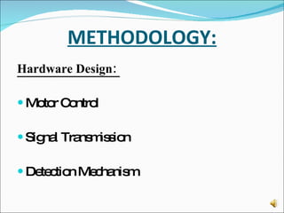
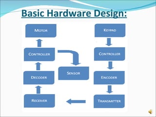
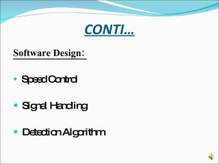
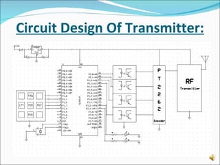
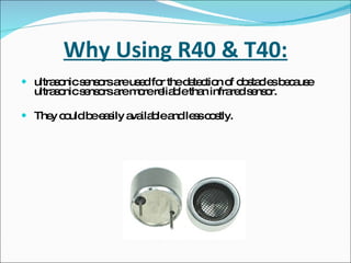
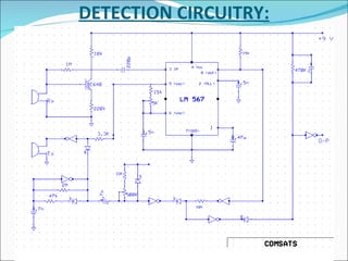
AUTONOMOUS & RC VEHICLE USING ULTRA-SONIC SENSERS
PROJECT ADVISOR: SIR USMAN RAFIQUE (Lecturer EE)
GROUP MEMBERS Mehtab Ejaz Qureshi CIIT/SP06-BTE-037/LHR Ijaz Ahmad CIIT/SP06-BTE-027/LHR Sibghat Ullah Khan CIIT/SP06-BTE-075/LHR Hammad Iqbal CIIT/SP06-BTE-022/LHR
INTRODUCTION: The “ Autonomous & RC Vehicle”  is a remote-controlled vehicle. In addition to the capability of being  controlled with a remote control, The “ Autonomous & RC Vehicle ” have a smart autonomous mode that allows the unit to move freely without running into major obstacles.
DESCRIPTION: Two Modes Of Operation Remote Control mode: A remote control vehicle is defined as any mobile device that is controlled by a means that does not restrict its motion with an origin external to the device. Controlling the vehicle with remote control.
CONTI… Autonomous mode: An autonomous vehicle is that vehicle that can drive itself from one place to another without help of driver. Obstacle detection and avoiding the obstacle.
OBJECTIVES: Remote controlled vehicle is consist of two major parts:  The Transmitter Unit. The Receiver Unit.
CONTI… Commands from the keypad is processed by a microcontroller unit, encoded and then transmitted by the RF transmitter at 300MHz. On the receiving end, received commands are decoded, processed by the microcontroller and translated to a series of  instructions.
CONTI… Another feature is of autonomous mode.  Under the autonomous mode, sensors are activated  to detect obstacles . Then outputs are monitor by the detection algorithm (code) that is running on the onboard microcontroller.  This algorithm acts accordingly and ensures the vehicle stays clear of obstacles.
METHODOLOGY: Hardware Design:  Motor Control Signal Transmission Detection Mechanism
Basic Hardware Design:
CONTI… Software Design:  Speed Control Signal Handling Detection Algorithm
Circuit Design Of Transmitter:
PHOTO-COUPLER: The photo-coupler is used in between the microcontroller and the transmitter. The basic purpose of using this component to avoid the frequency mismatch and to prevent the microcontroller from the reverse current. It is consist of diode and the transistor.
BASIC STRUCTURE:
ENCODER-PT2262: CMOS Technology. Low power consumption. Very high noise immunity. Up to six data pins. Wide range of operating voltage i.e. Vcc = 4 ~ 15 volts.
Circuit Design Of Receiver:
INVERTER ULN2003: This inverter is used to prevent the reverse voltage flow from the motor to the controller. It is consist of NOT gates and is very useful for driving a wide range of loads including DC motors, LED displays and high power buffers.
BASIC STRUCTURE:
MOTOR DRIVER L-298: L-298 is a high voltage, high current dual full-bridge driver designed to accept standard TTL logic levels and drive inductive loads such as relays, DC motors and stepping motors.
ULTRASONIC SENSORS: And LM 567
Why Using R40 & T40: ultrasonic sensors are used for the detection of obstacles because ultrasonic sensors are more reliable than infrared sensor. They could be easily available and less costly.
FEATURES:
Why Using LM567: general purpose tone decoders. Output wave fall time is 30ns. Output wave rise time is 150ns. Largest detection bandwidth is 10 to 13% of central frequency.
BASIC STRUCTURE:
DETECTION CIRCUITRY:
THANK YOU

Fyp 3rd Presentation

  • 1.
    AUTONOMOUS & RCVEHICLE USING ULTRA-SONIC SENSERS
  • 2.
    PROJECT ADVISOR: SIRUSMAN RAFIQUE (Lecturer EE)
  • 3.
    GROUP MEMBERS MehtabEjaz Qureshi CIIT/SP06-BTE-037/LHR Ijaz Ahmad CIIT/SP06-BTE-027/LHR Sibghat Ullah Khan CIIT/SP06-BTE-075/LHR Hammad Iqbal CIIT/SP06-BTE-022/LHR
  • 4.
    INTRODUCTION: The “Autonomous & RC Vehicle” is a remote-controlled vehicle. In addition to the capability of being controlled with a remote control, The “ Autonomous & RC Vehicle ” have a smart autonomous mode that allows the unit to move freely without running into major obstacles.
  • 5.
    DESCRIPTION: Two ModesOf Operation Remote Control mode: A remote control vehicle is defined as any mobile device that is controlled by a means that does not restrict its motion with an origin external to the device. Controlling the vehicle with remote control.
  • 6.
    CONTI… Autonomous mode:An autonomous vehicle is that vehicle that can drive itself from one place to another without help of driver. Obstacle detection and avoiding the obstacle.
  • 7.
    OBJECTIVES: Remote controlledvehicle is consist of two major parts: The Transmitter Unit. The Receiver Unit.
  • 8.
    CONTI… Commands fromthe keypad is processed by a microcontroller unit, encoded and then transmitted by the RF transmitter at 300MHz. On the receiving end, received commands are decoded, processed by the microcontroller and translated to a series of instructions.
  • 9.
    CONTI… Another featureis of autonomous mode. Under the autonomous mode, sensors are activated to detect obstacles . Then outputs are monitor by the detection algorithm (code) that is running on the onboard microcontroller. This algorithm acts accordingly and ensures the vehicle stays clear of obstacles.
  • 10.
    METHODOLOGY: Hardware Design: Motor Control Signal Transmission Detection Mechanism
  • 11.
  • 12.
    CONTI… Software Design: Speed Control Signal Handling Detection Algorithm
  • 13.
    Circuit Design OfTransmitter:
  • 14.
    PHOTO-COUPLER: The photo-coupleris used in between the microcontroller and the transmitter. The basic purpose of using this component to avoid the frequency mismatch and to prevent the microcontroller from the reverse current. It is consist of diode and the transistor.
  • 15.
  • 16.
    ENCODER-PT2262: CMOS Technology.Low power consumption. Very high noise immunity. Up to six data pins. Wide range of operating voltage i.e. Vcc = 4 ~ 15 volts.
  • 17.
  • 18.
    INVERTER ULN2003: Thisinverter is used to prevent the reverse voltage flow from the motor to the controller. It is consist of NOT gates and is very useful for driving a wide range of loads including DC motors, LED displays and high power buffers.
  • 19.
  • 20.
    MOTOR DRIVER L-298:L-298 is a high voltage, high current dual full-bridge driver designed to accept standard TTL logic levels and drive inductive loads such as relays, DC motors and stepping motors.
  • 21.
  • 22.
    Why Using R40& T40: ultrasonic sensors are used for the detection of obstacles because ultrasonic sensors are more reliable than infrared sensor. They could be easily available and less costly.
  • 23.
  • 24.
    Why Using LM567:general purpose tone decoders. Output wave fall time is 30ns. Output wave rise time is 150ns. Largest detection bandwidth is 10 to 13% of central frequency.
  • 25.
  • 26.
  • 27.