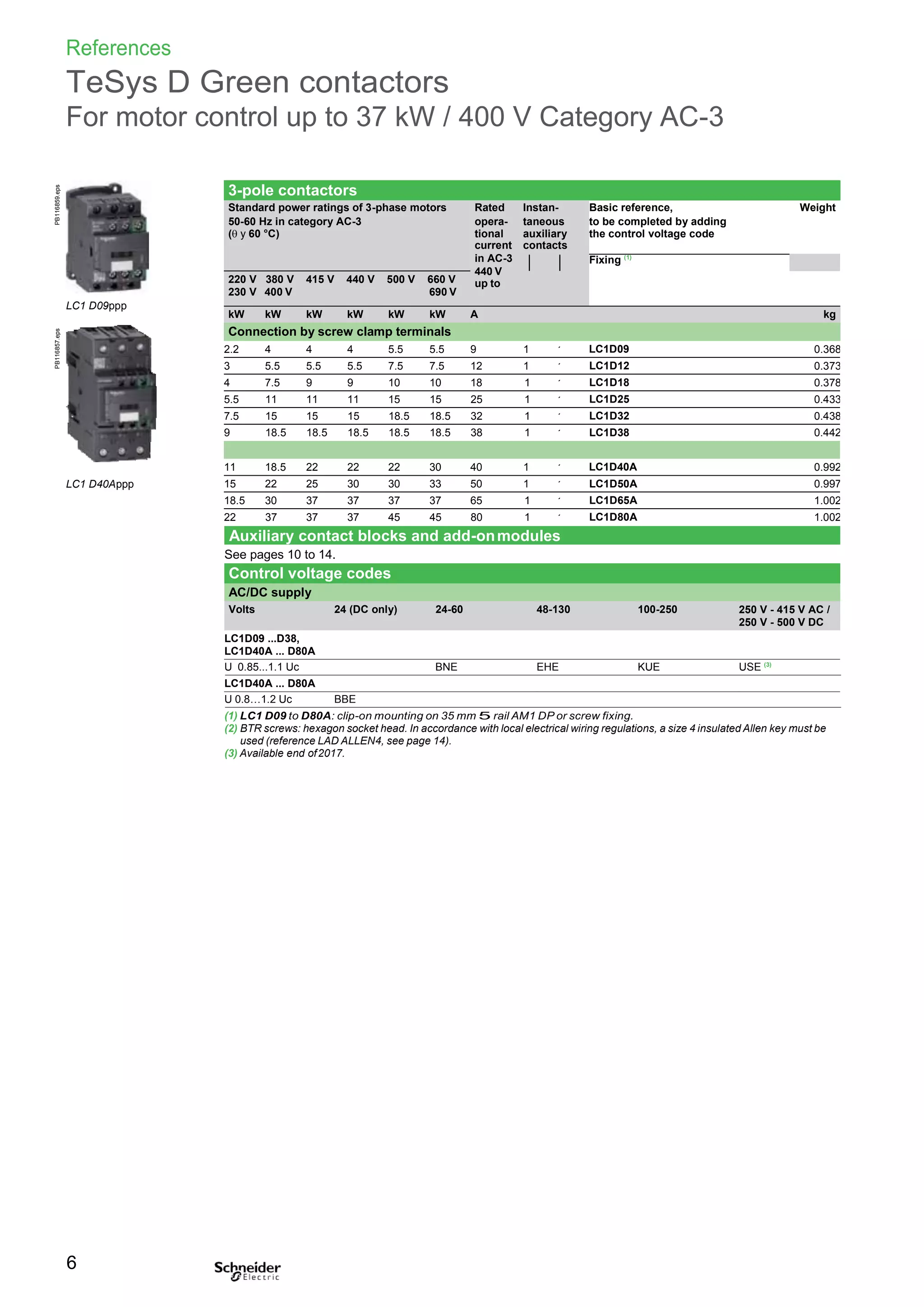
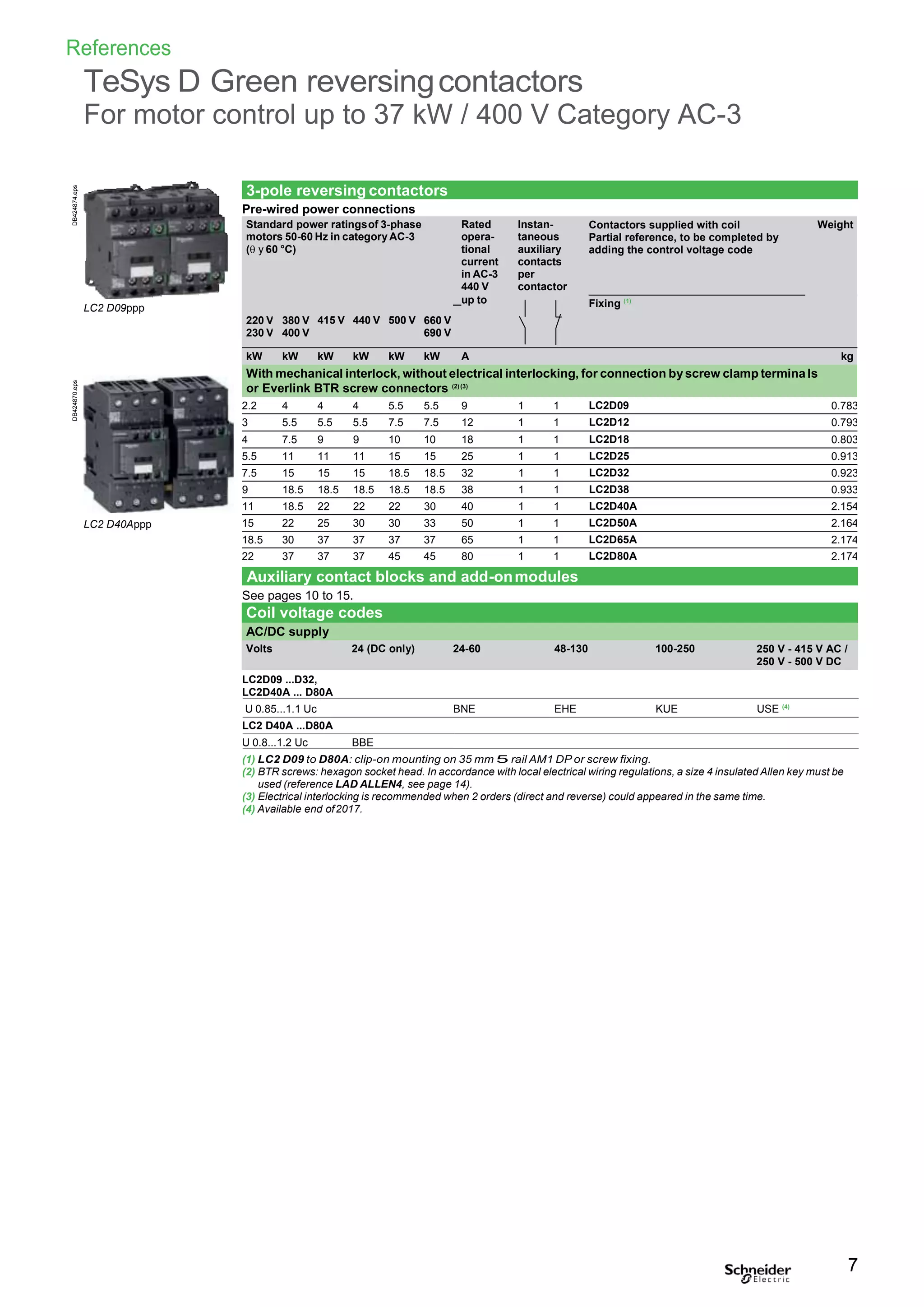
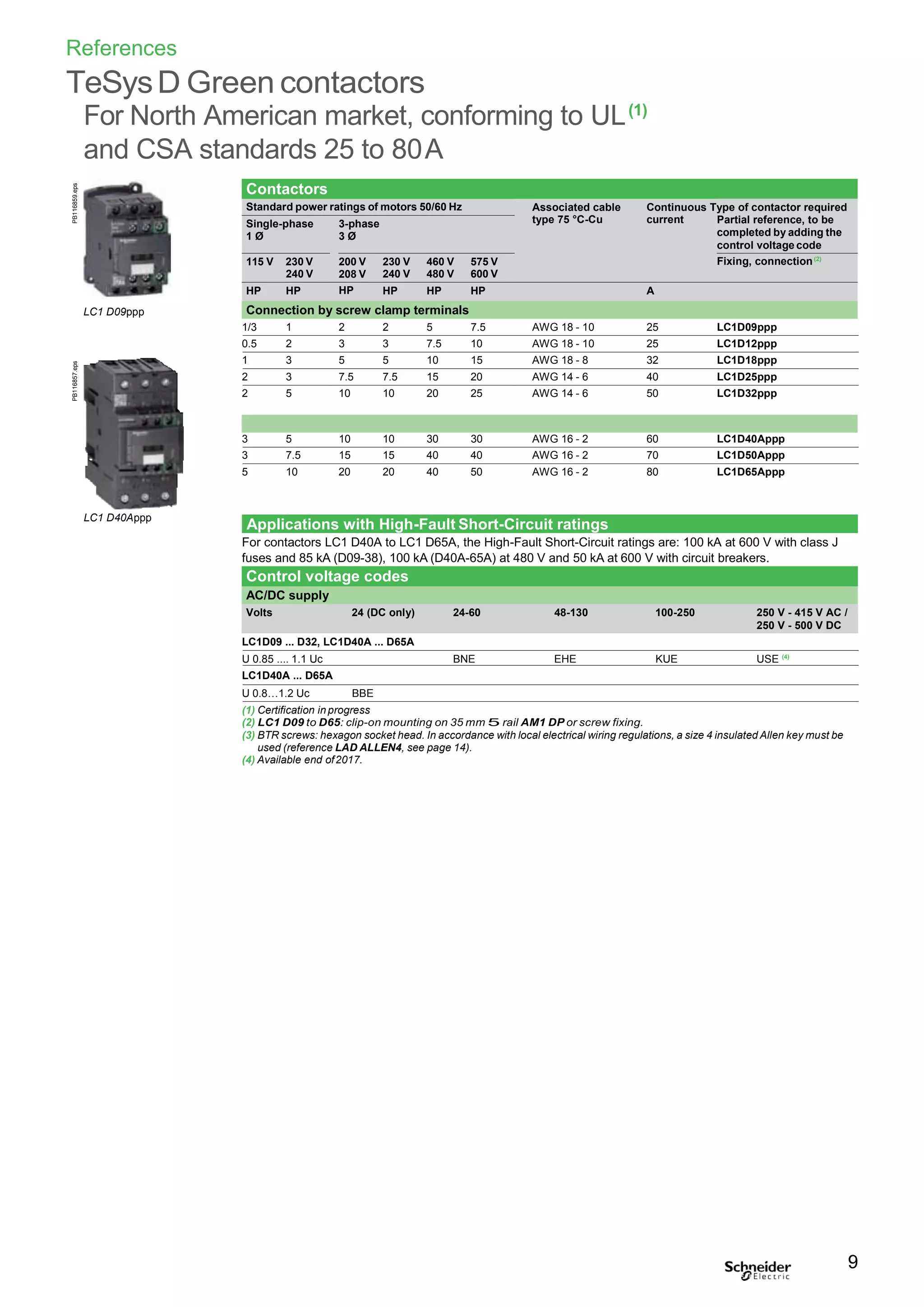
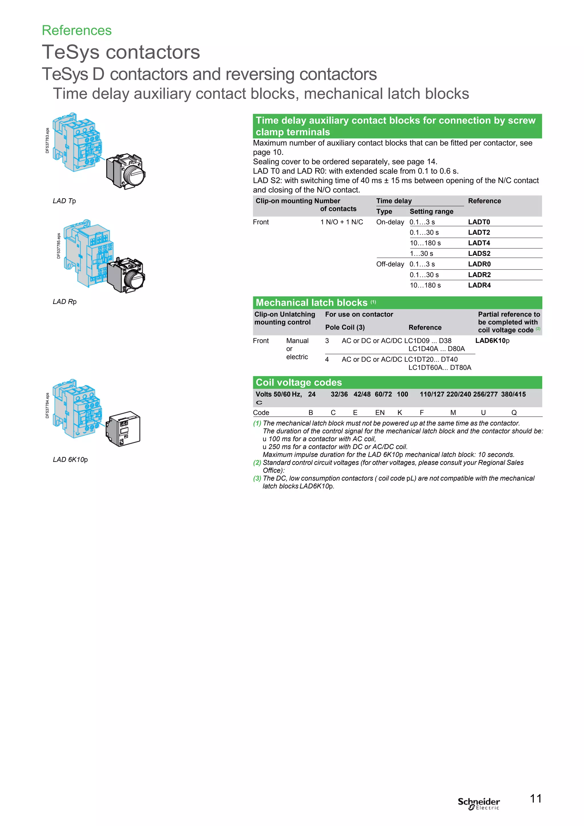
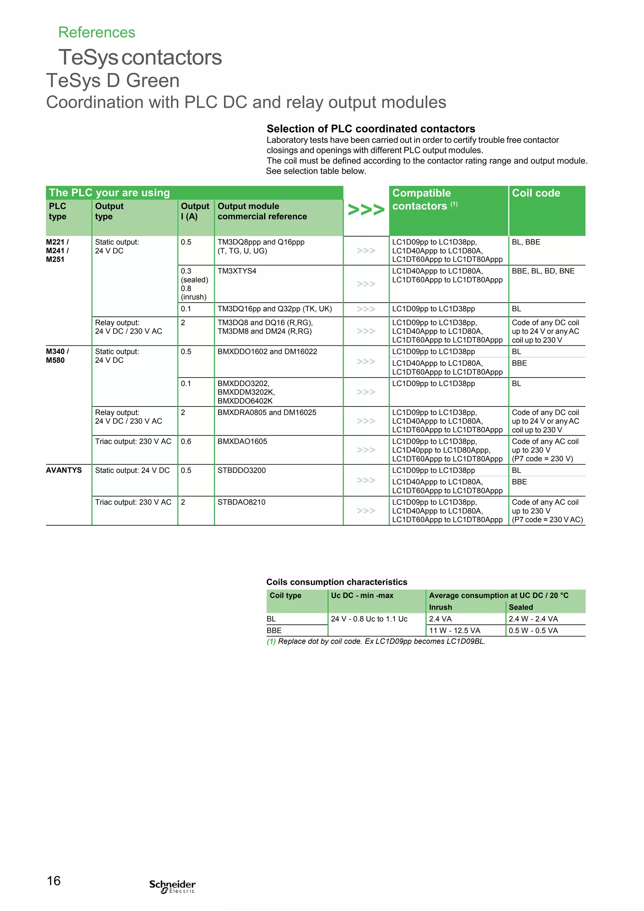
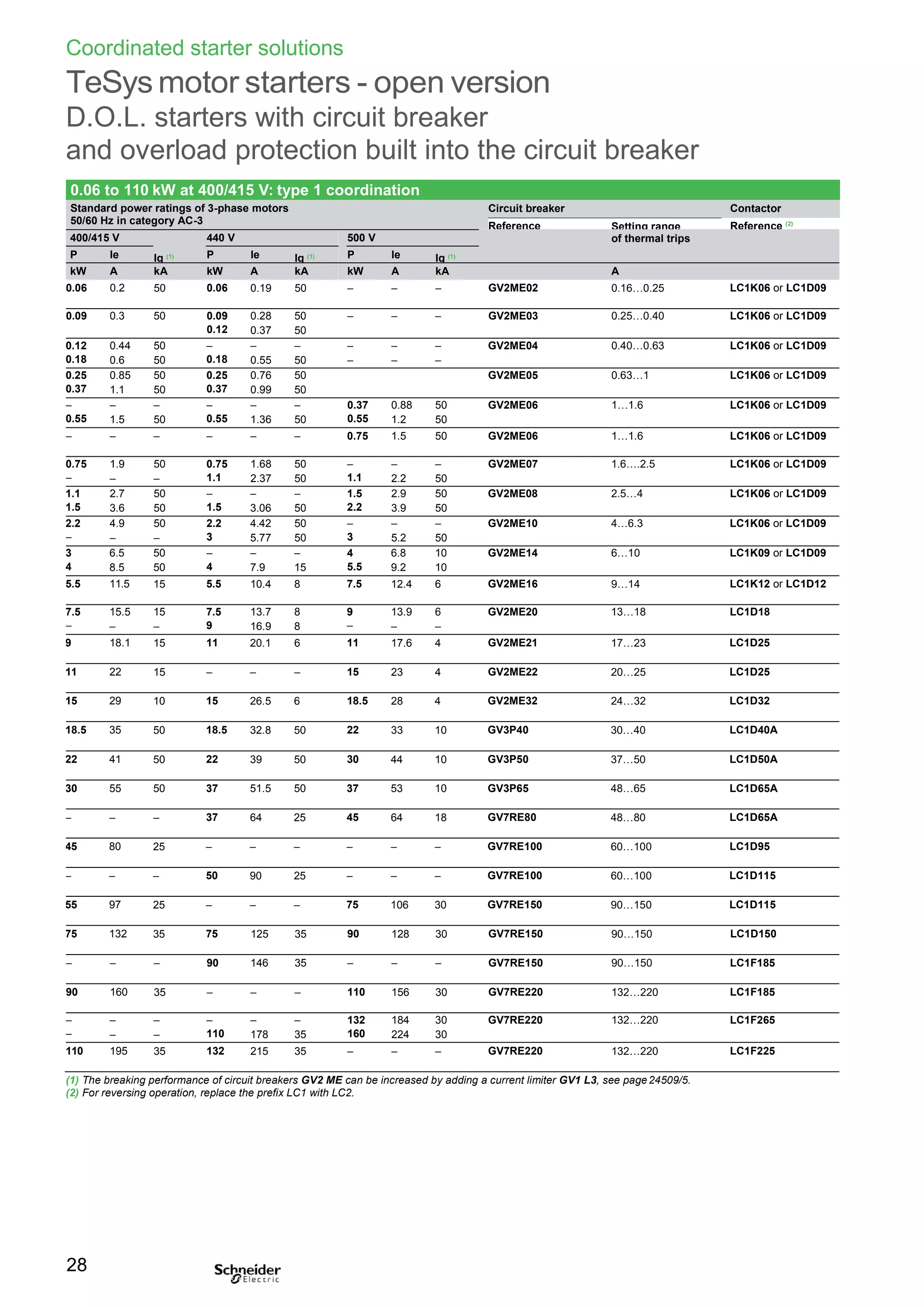
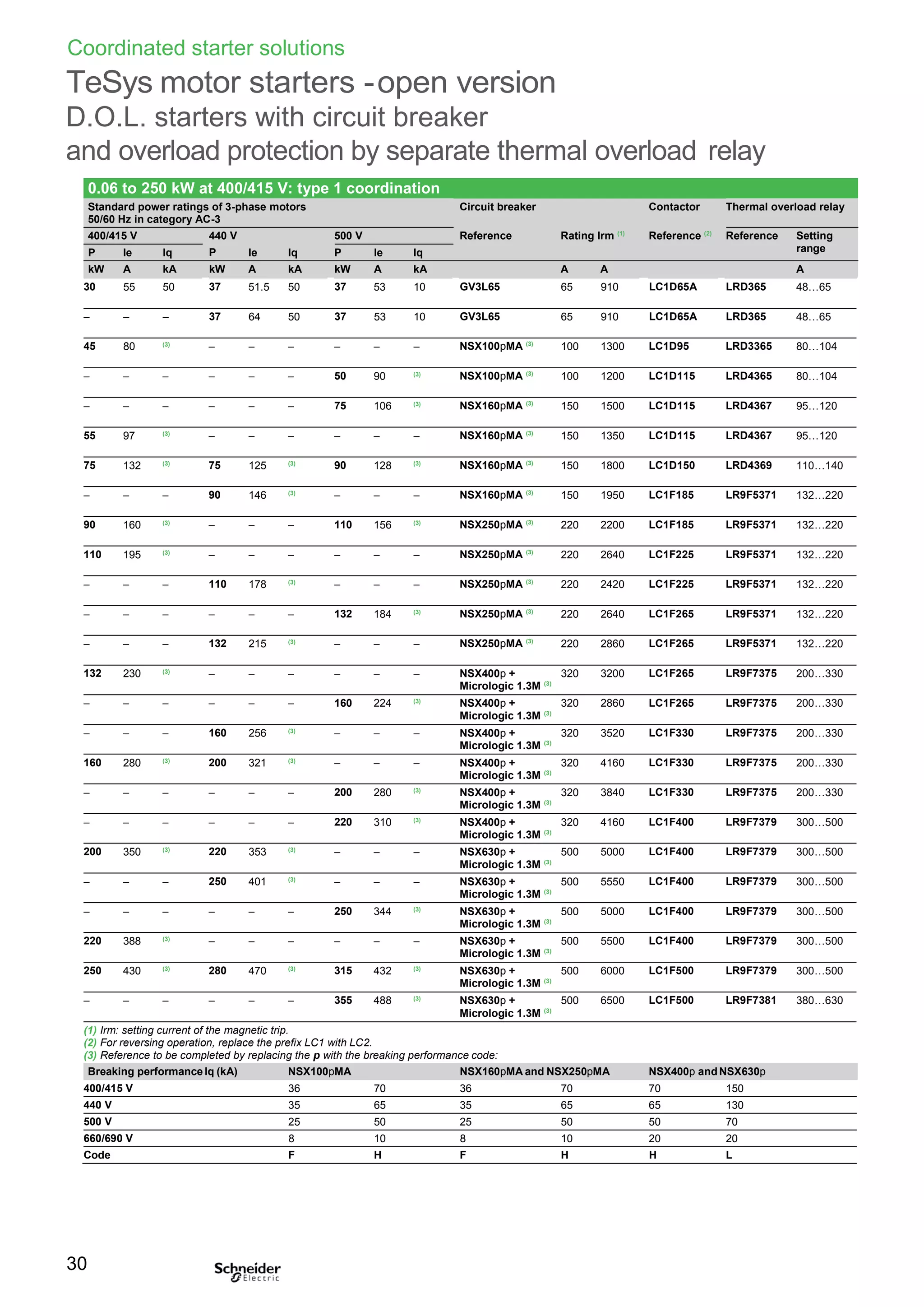
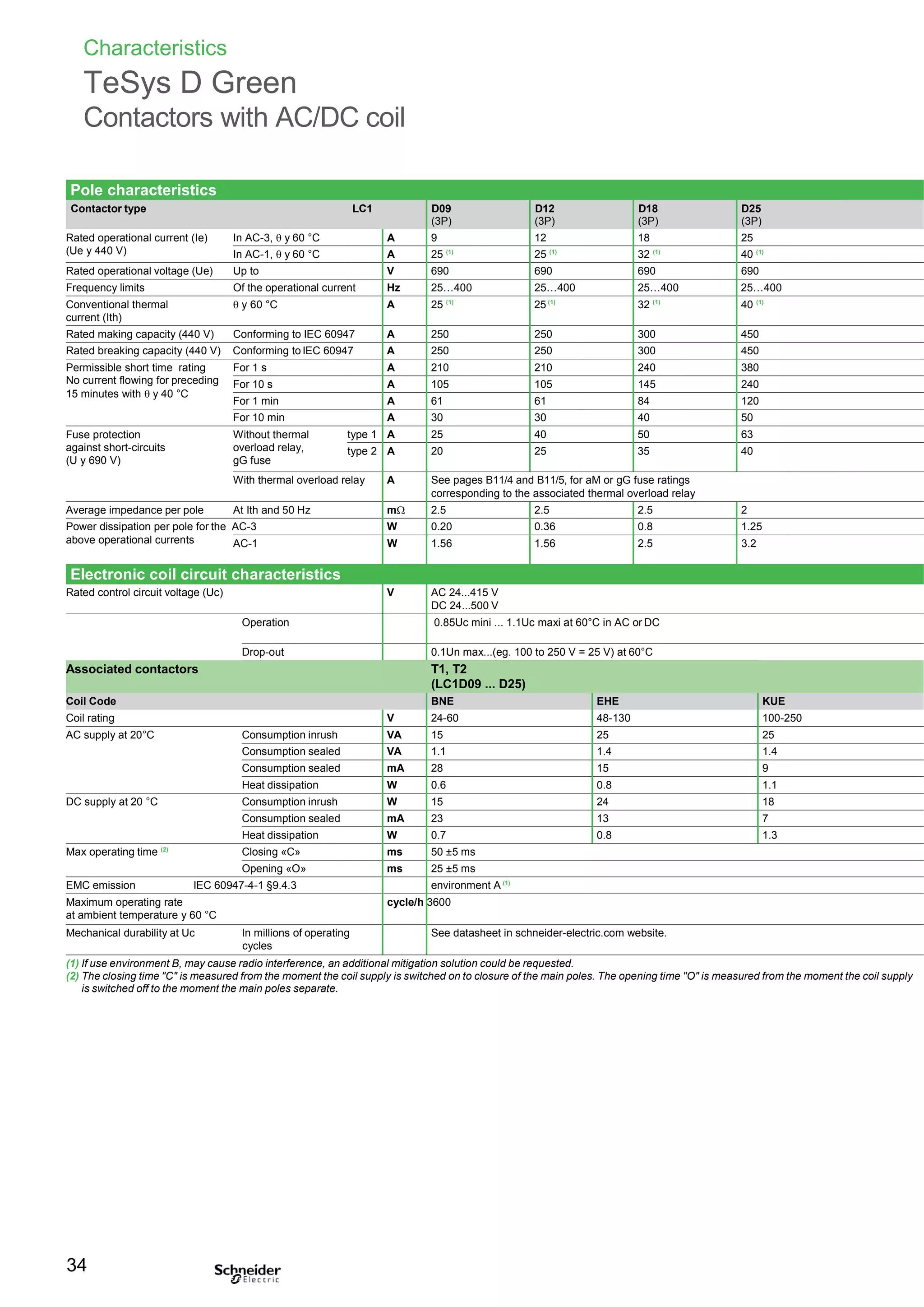
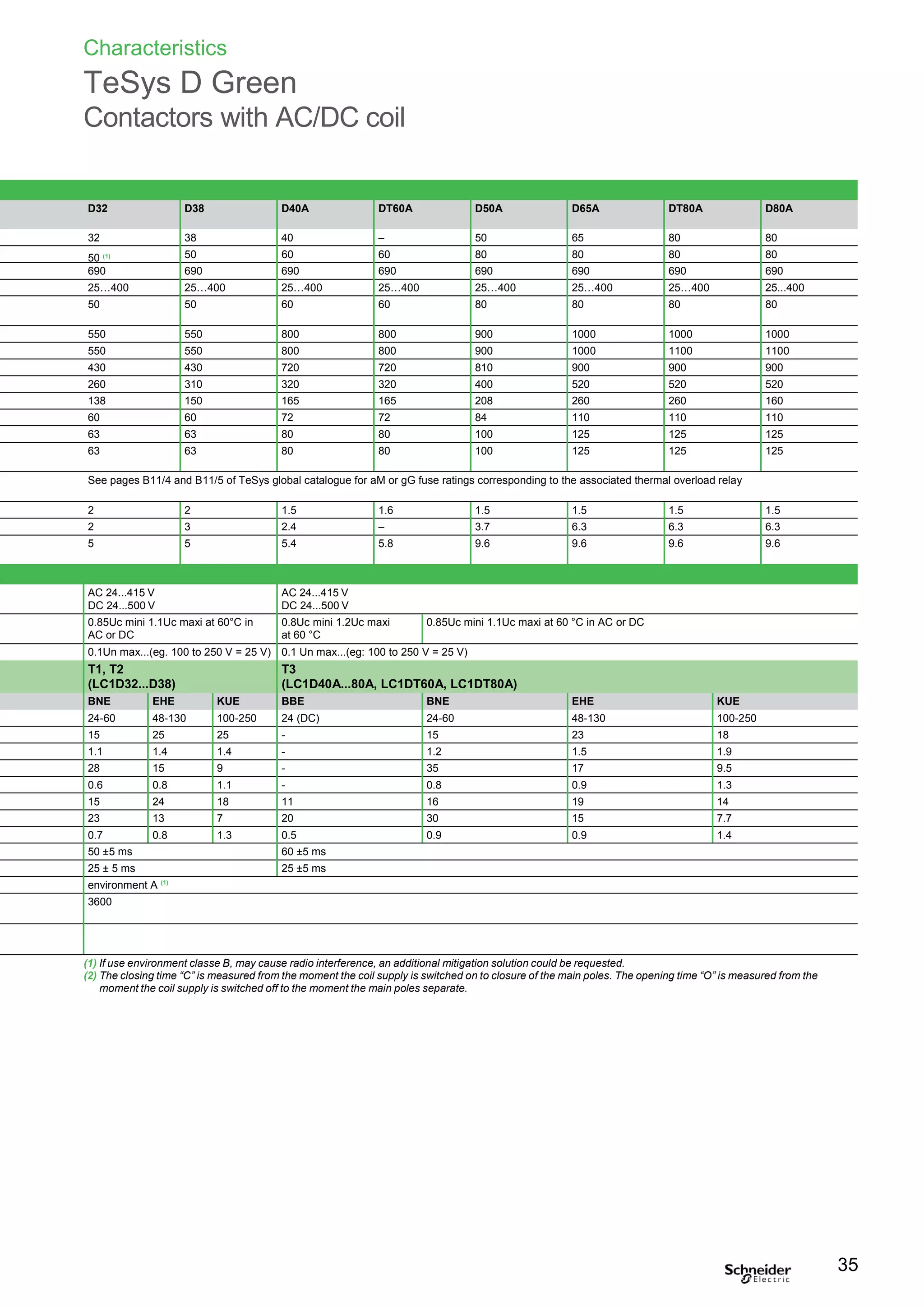
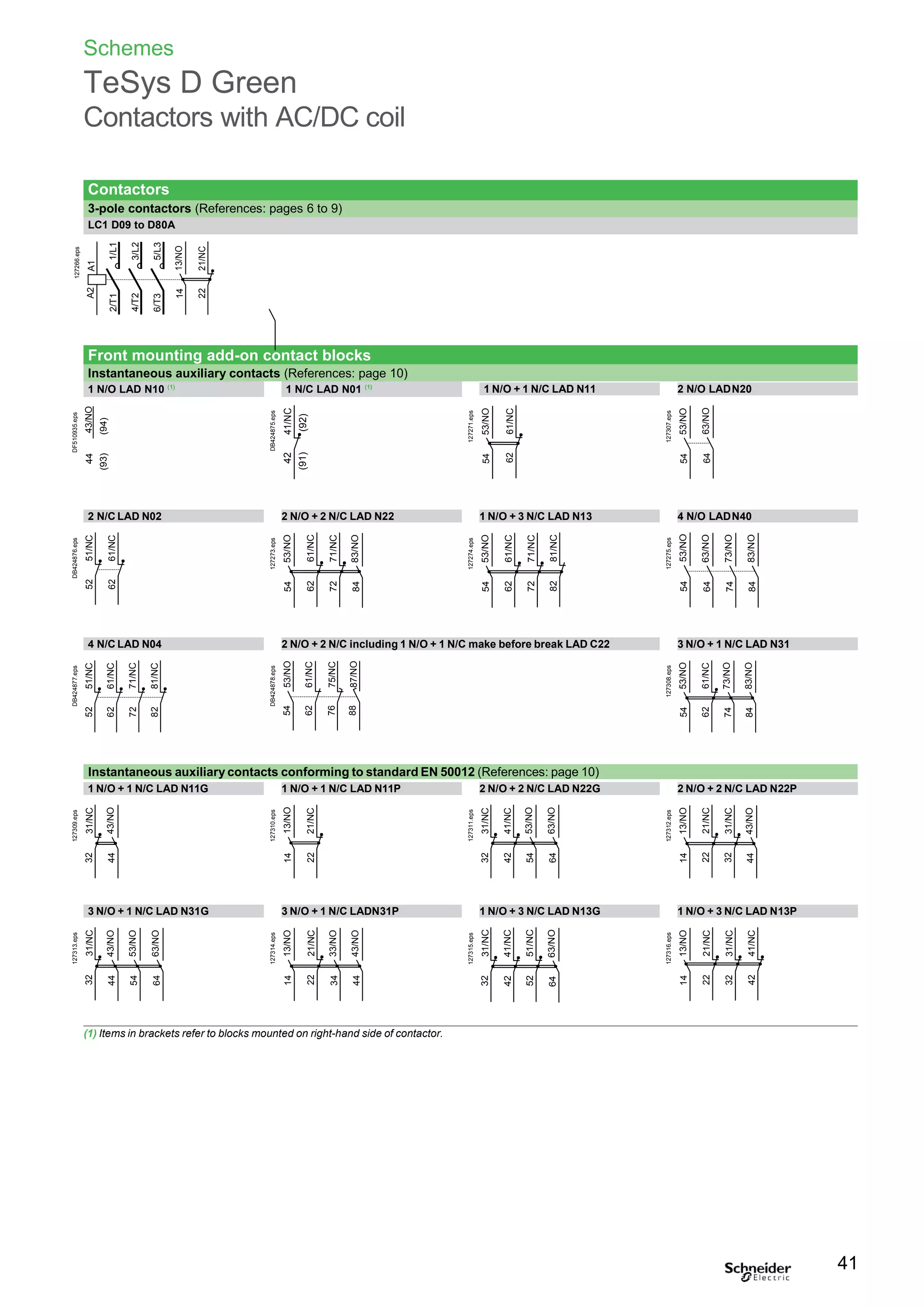
Mọi chi tiết xin vui lòng liên hệ trực tiếp để được hỗ trợ tốt nhất.
Phone - Zalo: 0944.240.317 - Email: Kinhdoanh1.hpe@gmail.com
Phone - Zalo: 0975.123.698 - Email: Kinhdoanh2.hpe@gmail.com
Phone - Zalo: 0961.008.858 - Email: Kinhdoanh3.hpe@gmail.com
TeSys D Greencontactors
Coordinatedstartersselectiontables 23
Technical Data for Designers 31
TeSys D legacy contactors 9 to 150 A, for motor control and
other applications.
25, 32, 38 A 80, 95 A
9, 12, 18 A
40, 50, 65 A 115, 150 A
Discover TeSys D
and other contactor
ranges in the TeSys
global catalogue.
Catalogue 2016
Motor control
and protection components
schneider-electric.com
TeSys
Contents
New TeSys D Green contactorsseries
with AC/DC coils
Page
Discovery 4
Contactors references 6
Auxiliaries, accessories references 10
Motor starters mounting and wiring systems 17
3
References
TeSys D Green contactors
For motor control up to 37 kW / 400 V Category AC-3
LC1 D09ppp
2.2 4 4 4 5.5 5.5 9 1 1 LC1D09 0.368
3 5.5 5.5 5.5 7.5 7.5 12 1 1 LC1D12 0.373
4 7.5 9 9 10 10 18 1 1 LC1D18 0.378
5.5 11 11 11 15 15 25 1 1 LC1D25 0.433
7.5 15 15 15 18.5 18.5 32 1 1 LC1D32 0.438
9 18.5 18.5 18.5 18.5 18.5 38 1 1 LC1D38 0.442
11 18.5 22 22 22 30 40 1 1 LC1D40A 0.992
LC1 D40Appp 15 22 25 30 30 33 50 1 1 LC1D50A 0.997
18.5 30 37 37 37 37 65 1 1 LC1D65A 1.002
22 37 37 37 45 45 80 1 1 LC1D80A 1.002
Auxiliary contact blocks and add-onmodules
See pages 10 to 14.
Control voltage codes
AC/DC supply
Volts 24 (DC only) 24-60 48-130 100-250 250 V - 415 V AC /
250 V - 500 V DC
LC1D09 ...D38,
LC1D40A ... D80A
U 0.85...1.1 Uc BNE EHE KUE USE (3)
LC1D40A ... D80A
U 0.8…1.2 Uc BBE
(1) LC1 D09 to D80A: clip-on mounting on 35 mm 5 rail AM1 DP or screw fixing.
(2) BTR screws: hexagon socket head. In accordance with local electrical wiring regulations, a size 4 insulated Allen key must be
used (reference LAD ALLEN4, see page 14).
(3) Available end of2017.
6
PB116857.eps
PB116859.eps
3-pole contactors
Standard power ratings of 3-phase motors Rated Instan- Basic reference, Weight
50-60 Hz in category AC-3
( y 60 °C)
opera-
tional
taneous
auxiliary
to be completed by adding
the control voltage code
current contacts
in AC-3 Fixing (1)
440 V
up to
220 V 380 V 415 V 440 V 500 V 660 V
230 V 400 V 690 V
kW kW kW kW kW kW A kg
Connection by screw clamp terminals
References
TeSys D Green reversingcontactors
For motor control up to 37 kW / 400 V Category AC-3
LC2 D09ppp
LC2 D40Appp
3-pole reversing contactors
Pre-wired power connections
Standard power ratingsof 3-phase Rated Instan-
motors 50-60 Hz in category AC-3 opera- taneous
( y 60 °C) tional auxiliary
current contacts
in AC-3 per
440 V contactor
Contactors supplied with coil
Partial reference, to be completed by
adding the control voltage code
Weight
220 V
230 V
380 V
400 V
415 V 440 V 500 V 660 V
690 V
up to Fixing (1)
kW kW kW kW kW kW A kg
With mechanical interlock, without electrical interlocking, for connection byscrew clamp termina
or Everlink BTR screw connectors (2) (3)
ls
2.2 4 4 4 5.5 5.5 9 1 1 LC2D09 0.783
3 5.5 5.5 5.5 7.5 7.5 12 1 1 LC2D12 0.793
4 7.5 9 9 10 10 18 1 1 LC2D18 0.803
5.5 11 11 11 15 15 25 1 1 LC2D25 0.913
7.5 15 15 15 18.5 18.5 32 1 1 LC2D32 0.923
9 18.5 18.5 18.5 18.5 18.5 38 1 1 LC2D38 0.933
11 18.5 22 22 22 30 40 1 1 LC2D40A 2.154
15 22 25 30 30 33 50 1 1 LC2D50A 2.164
18.5 30 37 37 37 37 65 1 1 LC2D65A 2.174
22 37 37 37 45 45 80 1 1 LC2D80A 2.174
Auxiliary contact blocks and add-onmodules
See pages 10 to 15.
Coil voltage codes
AC/DC supply
Volts 24 (DC only) 24-60 48-130 100-250 250 V - 415 V AC /
250 V - 500 V DC
LC2D09 ...D32,
LC2D40A ... D80A
U 0.85...1.1 Uc BNE EHE KUE USE (4)
LC2 D40A ...D80A
U 0.8...1.2 Uc BBE
(1) LC2 D09 to D80A: clip-on mounting on 35 mm 5 rail AM1 DP or screw fixing.
(2) BTR screws: hexagon socket head. In accordance with local electrical wiring regulations, a size 4 insulated Allen key must be
used (reference LAD ALLEN4, see page 14).
(3) Electrical interlocking is recommended when 2 orders (direct and reverse) could appeared in the same time.
(4) Available end of2017.
7
DB424870.eps
DB424874.eps
References
TeSysD Green contactors
For load control from 25 to 80 A CategoryAC-1
3-pole contactors
Non inductive loads Number Instan- Partial reference, Weight
maximum current of poles taneous to be completed byadding
( y 60 °C) auxiliary the control voltagecode
utilisation category contacts
LC1 D09ppp
AC-1 Fixing (1)
A kg
Connection by screw clamp terminals
25 3 1 1 LC1D09 Schneider 0.368
or LC1D12 Schneider 0.373
32 3 1 1 LC1D18 Schneider 0.378
40 3 1 1 LC1D25 Schneider 0.433
50 3 1 1 LC1D32 Schneider 0.438
or LC1D38 Schneider 0.442
60 3 1 1 LC1D40A Schneider 0.992
80 3 1 1 LC1D50A Schneider 0.997
LC1 D40Appp or LC1D65A Schneider 1.002
60 4 1 1 LC1DT60A
Schneider
1.230
80 4 1 1 LC1DT80A
Schneider
1.290
60 4 1 1 LC2DT60A 2.460
80 4 1 1 LC2DT80A 2.580
Control voltage codes
AC/DC supply
LC1 DT60Appp Volts 24 (DC only) 24-60 48-130 100-250 250 V -
/ 250 V -
415 VAC
500 VDC
LC1 D09…D65A and LCpDT60A...DT80A
U 0.85 .... 1.1 Uc BNE EHE KUE USE (5)
LC1D40 to LC1D65A, LCpDT60A to LCpDT80A
U 0.8…1.2 Uc BBE
(1) LC1 D09 to D65A, LCpDT60Aand LCpDT80A: clip-on mounting on 35 mm 5 rail AM1 DP
or screw fixing.
(2) BTR screws: hexagon socket head. In accordance with local electrical wiring regulations,
a size 4 insulated Allen key must be used (reference LAD ALLEN4, see page 14).
(3) Selection according to the number of operating cycles, see AC-1 curve, page 36.
(4) Available in 2018.
(5) Available end of2017.
8
DB424871.eps
PB116857.eps
PB116859.eps
4-pole contactors (4)
Connection by EverLink®
, BTR (2)
screw connectors
4-pole changeover contactors (4)
Connection by EverLink®
, BTR (2)
screw connectors
References
TeSysD Green contactors
For North American market, conforming to UL(1)
and CSA standards 25 to 80A
LC1 D09ppp
LC1 D40Appp
1/3 1 2 2 5 7.5 AWG 18 - 10 25 LC1D09ppp
0.5 2 3 3 7.5 10 AWG 18 - 10 25 LC1D12ppp
1 3 5 5 10 15 AWG 18 - 8 32 LC1D18ppp
2 3 7.5 7.5 15 20 AWG 14 - 6 40 LC1D25ppp
2 5 10 10 20 25 AWG 14 - 6 50 LC1D32ppp
3 5 10 10 30 30 AWG 16 - 2 60 LC1D40Appp
3 7.5 15 15 40 40 AWG 16 - 2 70 LC1D50Appp
5 10 20 20 40 50 AWG 16 - 2 80 LC1D65Appp
Applications with High-Fault Short-Circuit ratings
For contactors LC1 D40A to LC1 D65A, the High-Fault Short-Circuit ratings are: 100 kA at 600 V with class J
fuses and 85 kA (D09-38), 100 kA (D40A-65A) at 480 V and 50 kA at 600 V with circuit breakers.
Control voltage codes
AC/DC supply
Volts 24 (DC only) 24-60 48-130 100-250 250 V - 415 V AC /
250 V - 500 V DC
LC1D09 ... D32, LC1D40A ... D65A
U 0.85 .... 1.1 Uc BNE EHE KUE USE (4)
LC1D40A ... D65A
U 0.8…1.2 Uc BBE
(1) Certification in progress
(2) LC1 D09 to D65: clip-on mounting on 35 mm 5 rail AM1 DP or screw fixing.
(3) BTR screws: hexagon socket head. In accordance with local electrical wiring regulations, a size 4 insulated Allen key must be
used (reference LAD ALLEN4, see page 14).
(4) Available end of2017.
9
Contactors
Standard power ratings of motors 50/60 Hz
Single-phase
1 Ø
3-phase
3 Ø
Associated cable
type 75 °C-Cu
Continuous Type of contactor required
current
115 V 230 V
240 V
Partial reference, to be
completed by adding the
control voltage code
Fixing, connection(2)
HP HP
200 V
208 V
HP
230 V 460 V 575 V
240 V 480 V 600 V
HP HP HP A
Connection by screw clamp terminals
PB116857.eps
PB116859.eps
References
TeSys contactors
TeSys D contactors and reversing contactors
Instantaneous auxiliary contact blocks
Instantaneous auxiliary contact blocks for connection by screw clampterminals
For use in normal operating environments
Front 1 – – – 1 – LADN10
– – – – 1 LADN01
2 – – – 1 1 LADN11
– – – 2 – LADN20
– – – – 2 LADN02
4 – – – 2 2 LADN22 LADN22S (1)
– – – 1 3 LADN13
– – – 4 – LADN40
– – – – 4 LADN04
– – – 3 1 LADN31
4 incl. 1 N/O & 1 N/C make before break – – – 2 2 LADC22
Side 2 – – – 1 1 LAD8N11
– – – 2 – LAD8N20
– – – – 2 LAD8N02
For terminal referencing conforming to EN50012
Front on 3P contactors and
4P contactors 20 to 80 A
2 – – – 1 1 LADN11G
4 – – – 2 2 LADN22G
With dust and damp protected contacts, for use in particularly harsh industrial environments
Front 2 – 2 – – – LA1DX20
1 1 – – – LA1DX11
2 – – – – LA1DX02
– 2 2 – – LA1DY20 (2)
4 – 2 – 2 – LA1DZ40
– 2 – 1 1 LA1DZ31
AC/DC 3P LC1 D09…D38 1 on Right Hand side and – 1 or 1 or 1
compatible LC1 D40A…D80A 1 on RH or LH side and – 1 or 1 or 1
4P LC1 DT60A and DT80A 1 on RH or LH side and – 1 or 1 or 1
(1) With red front face - for safety chain indication.
(2) Device fitted with 4 earth screen continuity terminals.
10
DB423133R.eps
Maximum number of auxiliary contacts per rating
Contactors Instantaneous auxiliary contacts Time delay
Coil Pole Rating ref. Side mounted Front mounted
1 contact 2 contact 4 contact
Front
mounted
References
TeSys contactors
TeSys D contactors and reversing contactors
Time delay auxiliary contact blocks, mechanical latch blocks
LAD Tp
Maximum number of auxiliary contact blocks that can be fitted per contactor, see
page 10.
Sealing cover to be ordered separately, see page 14.
LAD T0 and LAD R0: with extended scale from 0.1 to 0.6 s.
LAD S2: with switching time of 40 ms ± 15 ms between opening of the N/C contact
and closing of the N/O contact.
LAD Rp
Front 1 N/O + 1 N/C On-delay 0.1…3 s LADT0
0.1…30 s LADT2
10…180 s LADT4
1…30 s LADS2
Off-delay 0.1…3 s LADR0
0.1…30 s LADR2
10…180 s LADR4
Front Manual
or
electric
3 AC or DC or AC/DC LC1D09 ... D38
LC1D40A ... D80A
4 AC or DC or AC/DC LC1DT20... DT40
LC1DT60A... DT80A
LAD6K10p
Coil voltage codes
Volts 50/60 Hz, 24 32/36 42/48 60/72 100 110/127 220/240 256/277 380/415
c
LAD 6K10p
Code B C E EN K F M U Q
(1) The mechanical latch block must not be powered up at the same time as the contactor.
The duration of the control signal for the mechanical latch block and the contactor should be:
u 100 ms for a contactor with AC coil,
u 250 ms for a contactor with DC or AC/DC coil.
Maximum impulse duration for the LAD 6K10p mechanical latch block: 10 seconds.
(2) Standard control circuit voltages (for other voltages, please consult your Regional Sales
Office):
(3) The DC, low consumption contactors ( coil code pL) are not compatible with the mechanical
latch blocks LAD6K10p.
11
Time delay auxiliary contact blocks for connection by screw
clamp terminals
Setting range
Type
Reference
Time delay
Clip-on mounting Number
of contacts
DF537784.eps
DF537783.eps
DF537785.eps
Mechanical latch blocks (1)
Clip-on Unlatching
mounting control
For use on contactor
Pole Coil (3) Reference
Partial reference to
be completed with
coil voltage code (2)
References
TeSys contactors
TeSys D contactors and reversing contactors
Accessories
b To be mounted on 3P contactors LC1D40A to D80A using LAD4BB3 wiring
adapter (to be ordered separatly).
On-delay type
Operational voltage a Time delay Reference
24…250 V
LC1D40A ... LC1D80A 0.1…2 s LA4DT0U
1.5…30 s LA4DT2U
25…500 s LA4DT4U
Static relay interface module
b To be mounted on 3P contactors LC1D40A to D80A using LAD4BB3 wiring
adapter (to be ordered separatly).
Relay interface with "AUTO-I" manual override switch (output forced “ON”),
solid state type
Operational voltage a Supply Reference
voltage
E1-E2 (c)
24…250 V
LC1 D40A…D80A 24 V LA4DWB
Wiring adapter
b For use with LADTpp timer module, LAD4DWB static relay interface module or
for adapting existing top terminals wiring (old contactor) to front terminals (new 3P
contactor).
Module with extension cables
For use on Reference
contactors
LC1 D40A…D80A Without coil suppression LAD4BB3
(1) The contactor must be fitted with a BNE, or BBE coil.
12
Electronic serial timer modules (1)
DB423134.eps
References
TeSys contactors
TeSys D contactors and reversing contactors
Accessories
LA9 D3260
LAD 96570
LAD9P3
13
Accessories for main pole and control connections
Description For use withcontactors LC1 Sold in Unit
AC / DC lots of reference
DF537797.eps
DF537794.eps
DF537792.eps
Connectors for cable, size
(1 connector)
3-pole 25 mm2
D09…D38 1 LA9D3260
EverLink®
terminal block
3-pole D40A…D80A 1 LAD96560
Protective covers
for connectors for lug type
terminals
3-pole D40A6…D80A 1 LAD96570
IP 20 covers for lug type
terminals (for mounting with
circuit breakers GV3 Ppp6
and GV3 Lpp6)
3 poles D40A6…D80A 1 LAD96575
Links for 2 poles D09…D38 D09…D38 10 LA9D2561
parallel connection of D40A…D80A 1 LAD9P32
3 poles D09…D38 D09…D38 10 LAD9P3 (1)
D40A…D80A 1 LAD9P33
References
TeSys contactors
TeSys D contactors and reversing contactors
Accessories
Power connection accessories
Terminal block For supply to one or more GV2 G busbar sets GV1G09
GV2 G245
Set of 63 A busbars
for parallelling of contactors
Set of 115 A busbars
for parallelling of contactors
2 contactors LC1 D09…D18 or D25…D38 GV2G245
4 contactors LC1 D09…D18 or D25…D38 GV2G445
2 contactors LC1 D40A…D80A GV3G264
3 contactors LC1 D40A…D80A GV3G364 (1)
Set of S-shape busbars For circuit breakers GV3 Ppp and GV3 Lpp
and contactors LC1 D40A…D65A
GV3S
Protection accessories
Description Use Sold in
lots of
Reference
Miniature control
circuit fuseholder
5 x 20 with 4 A-250 V fuse 1 LA9D941
Sealing cover For LAD T, LAD R 1 LA9D901
GV1 G09
Safety cover
preventing access to
the moving contactcarrier
LC1 D09…D80A 1 LAD9ET1
Red cover (for safety chain indication) 1 LAD9ET1S
GV3 S
Bag of 300 blank legends
self-adhesive, 7 x 21 mm
On holder LA9 D92 1 LA9D93
“SIS Label”
labelling software
supplied on CD-Rom
Multi-language version:
English, French, German, Italian,
Spanish
1 XBY2U
LA9 D941
Mounting accessories
Retrofit plate
for screw fixing
Size 4 Allen key, insulated,
1000 V
For replacement of LC1 D40 to D65
by LC1 D40A to D80A
For use on contactors
LC1 D40A to LC1 D150
1 LAD7X3
5 LADALLEN4
LAD 9ETp (1) With this set of busbars, any one contactor can be supplied directly by its EverLink®
double cage power terminal block.
The other two contactors are supplied by the busbar set. The 115A limitation is therefore applied to these two contactors.
Example: 1 LC1 D65A supplied directly + 1 contactor LC1 D65A and 1 contactor LC1 D50 A supplied via the busbar set =
115 A. This combination is compatible with busbar set GV3 G364.
(2) These legends are for sticking onto the safety cover of the contactors or add-on block, if fitted.
LAD 7X3
14
DF537804.eps
DF510995.eps
DF537803.eps
DF537802.eps
DF510994.eps
DF537799.eps
Marking accessories
Description Use Sold in
lots of
Unit
reference
Sheet of 64 blank legends,
self-adhesive, 8 x 33 mm (2)
Contactors (except 4P)
LAD N (4 contacts), LA6 DK
10 LAD21
Sheet of 112 blank legends,
self-adhesive, 8 x 12 mm (2)
LAD N (2 contacts),
LAD T, LAD R, LRD
10 LAD22
Sheet of 440 blank legends
for marking using plotter
or 8 x 12 mm engraver
All products 35 LAD24
Marker holder
snap-in, 8 x 18 mm
LC1 D09...D80A, LC1 DT60...DT80A,
LAD N (4 contacts), LAD T, LAD R
100 LAD90
References
TeSyscontactors
Component parts for assembling reversing
or changeover contactors pairs
For 3-pole reversing contactors for motorcontrol
Contactors with screw clamp terminals or connectors. Horizontally mounted, assembled by customer.
Description For contactors (1)
Reference
(2 identical contactors)
Kits for assembly of reversing contactors
LAD 9R1
Kit comprising:
b a mechanical interlock LAD 9V2
with electrical interlocking LAD9V1
b a set of power connections LAD 9V5 (parallel)
and LAD 9V6 (reversing).
Kit comprising:
b a mechanical interlock LAD 9V2
without electrical interlocking
b a set of power connections LAD 9V5 (parallel)
and LAD 9V6 (reversing).
Kit comprising:
b a mechanical interlock LAD 4CM
b a set of power connections LA9 D65A69.
LC1 D09 to D38 LAD9R1V
LC1 D09 to D38 LAD9R1
LC1 D40A to D80A LAD9R3
Mechanical interlocks
LAD 9R3 Mechanical interlock without
integral electrical interlocking
LC1 D09 to D38 LAD9V2
LC1 D40A to D80A LAD4CM
Sets of power connections
Comprising:
b a set of parallel bars
b a set of reverser bars.
LC1 D09 to D38 with screw
clamp terminals or connectors
LC1 D09…D32 with
spring terminal connections
LAD9V5 + LAD9V6
LAD9V12 + LAD9V13 (2)
LC1 D40A to D80A LA9D65A69
For star-delta starter
Description For contactors Reference
Mounting kit comprising: LC1 D09 and D12 LAD91217
b 1 time delay contact block LAD S2 (LC1 D09…D80), LC1 D18to D32 LAD93217
b power circuit connections (LC1 D09…D80), LC1 D40A and D50A LAD9SD3
b hardware required for fixing the contactors onto the
mounting plate (LC1 D80). LC1 D80A LA9D8017
Equipment mounting plates LC1 D09, D12 and D18 LA9D12974
LC1 D32 LA9D32974
LC1 D40A and D50A –
LC1 D80A LA9D80973
For 3-pole changeover contactor pairs
Contactors with screw clamp terminals or connectors. Horizontally mounted, assembled by customer.
Description For contactors (1)
Reference
(2 identical contactors)
Mechanical interlocks
Without integralelectrical interlocking LC1 D40A…D80A LAD9R3S
LA9 D8070 (1) To order the 2 contactors: see page 7.
(2) To assemble a reversing contactor with spring terminal connections, the following components must be ordered:
- 1 mechanical interlock LAD 9V2,
- 1 upstream power connection kit and 1 downstream power connection kit.
Upstream power connection kit LAD 9V10: installed in the Quickfit system with power connection module LAD 34.
(If module LAD 34 is not used, replace LAD 9V10 with LAD 9V12).
Downstream power connection kit LAD 9V11: installed in the Quickfit system with outgoing terminal block LAD 331.
(If LAD 331 is not used, replace LAD 9V11 with LAD 9V13).
15
DB423141.eps
DF537730.eps
DF537729.eps
References
TeSyscontactors
TeSys D Green
Coordination with PLC DC and relay output modules
Selection of PLC coordinated contactors
Laboratory tests have been carried out in order to certify trouble free contactor
closings and openings with different PLC output modules.
The coil must be defined according to the contactor rating range and output module.
See selection table below.
The PLC your are using
>>>
Compatible
contactors (1)
Coil code
PLC
type
Output
type
Output
I (A)
Output module
commercial reference
M221 /
M241 /
M251
Static output:
24 V DC
0.5 TM3DQ8ppp and Q16ppp
(T, TG, U, UG) >>>
LC1D09pp to LC1D38pp,
LC1D40Appp to LC1D80A,
LC1DT60Appp to LC1DT80Appp
BL, BBE
0.3
(sealed)
0.8
(inrush)
TM3XTYS4
>>>
LC1D40Appp to LC1D80A,
LC1DT60Appp to LC1DT80Appp
BBE, BL, BD, BNE
0.1 TM3DQ16pp and Q32pp (TK, UK) >>> LC1D09pp to LC1D38pp BL
Relay output:
24 V DC / 230 V AC
2 TM3DQ8 and DQ16 (R,RG),
TM3DM8 and DM24 (R,RG) >>>
LC1D09pp to LC1D38pp,
LC1D40Appp to LC1D80A,
LC1DT60Appp to LC1DT80Appp
Code of any DC coil
up to 24 V or any AC
coil up to 230 V
M340 /
M580
Static output:
24 V DC
0.5 BMXDDO1602 and DM16022
>>>
LC1D09pp to LC1D38pp BL
LC1D40Appp to LC1D80A,
LC1DT60Appp to LC1DT80Appp
BBE
0.1 BMXDDO3202,
BMXDDM3202K,
BMXDDO6402K
>>>
LC1D09pp to LC1D38pp BL
Relay output:
24 V DC / 230 V AC
2 BMXDRA0805 and DM16025
>>>
LC1D09pp to LC1D38pp,
LC1D40Appp to LC1D80A,
LC1DT60Appp to LC1DT80Appp
Code of any DC coil
up to 24 V or any AC
coil up to 230 V
Triac output: 230 V AC 0.6 BMXDAO1605
>>>
LC1D09pp to LC1D38pp,
LC1D40ppp to LC1D80Appp,
LC1DT60Appp to LC1DT80Appp
Code of any AC coil
up to 230 V
(P7 code = 230 V)
AVANTYS Static output: 24 V DC 0.5 STBDDO3200
>>>
LC1D09pp to LC1D38pp BL
LC1D40Appp to LC1D80A,
LC1DT60Appp to LC1DT80Appp
BBE
Triac output: 230 V AC 2 STBDAO8210
>>>
LC1D09pp to LC1D38pp,
LC1D40Appp to LC1D80A,
LC1DT60Appp to LC1DT80Appp
Code of any AC coil
up to 230 V
(P7 code = 230 V AC)
Coils consumption characteristics
Coil type Uc DC - min -max Average consumption at UC DC / 20 °C
Inrush Sealed
BL 24 V - 0.8 Uc to 1.1 Uc 2.4 VA 2.4 W - 2.4 VA
BBE 11 W - 12.5 VA 0.5 W - 0.5 VA
(1) Replace dot by coil code. Ex LC1D09pp becomes LC1D09BL.
16
Contents
Motor starters mounting and wiringsystems
using TeSys D contactors and TeSys GV circuitbreakers
Page
Linergy BZ
Snap-on mounting plates, busbar chassis
18
Linergy HK
Hot-plug, snap-on mounting plates, pluggable busbar
19
TeSys GV
Adapter plates, comb busbars
20
TeSys SoLink
Prefabricated monitoring/control
wiring modules for motor starters
21
17
Motor starters mounting and wiring systems
Mounting + power wiring system for TeSys D, GV
Linergy BZ
Snap-on mounting plates, busbar chassis
Motor starters applications
Linergy BZ is intended for compact, modular, motor starters composition:
Direct-On-Line or reversing.
Every starter is composed of:
b 1 snap-on mounting plate + 1 GV2 or GV3 circuitbreaker
+ 1 moulded connector + 1 LC1D contactor
Or
b 1 snap-on mounting plate + 1 TeSys U all-in-one starter.
Mounting plates:
b 25, 32 or 63 A
b single, double width (45, 90 mm)
b DIN rail fixing bracket for c. b. + contactor assemblies.
Electrical power distribution applications
Linergy BZ provides power supply to the directly connected starters and branch
circuits.
The busbar system is composed of mounting brackets, copper bars (not provided by
Schneider Electric), terminals, connection modules, insulating covers.
LA9ZA32621 mounting plate,
GV2AF01 combination block
18
Terminal plate, for busbar
supply connection Mounting plates
for motor starters,
Direct-On-Line or Reverse
Motor circuit breaker and contactor
assembly, equipped with mounting
plate and RJ45 connection module
(for control and command)
Click HERE for immediate download of Linergy Chapter.
chapter B1 Catalogue ref MKTED210011EN
> For more details, download: TeSys – Motor control and protection components catalogue -
DB400246.eps
Mounting + power wiring system for TeSys D, GV
Linergy HK
Hot-plug, snap-on mounting plates, pluggable busbar
AK5PA232
AK5PA532
Motor starters applications
Linergy HK is intended for compact, modular, motor starters composition:
Direct-On-Line or reversing.
Every starter is composed of:
b 1 pluggable mounting plate + 1 modular or GV2 or GV3 circuit breaker
b 1 pluggable mounting plate + 1 GV2 or GV3 circuit breaker
+ 1 connector + 1 LC1D contactor
Or
b 1 pluggable mounting plate + 1 TeSys U all-in-one starter.
Mounting plates:
b 25 or 50 A
b single, double width (54, 108 mm)
b DIN rail fixing bracket for c. b. + contactor assemblies.
Electrical power distribution applications
Linergy HK provides power supply to the directly connected starters and branch
circuits, with hot-plug possibilities for easier maintenance.
The busbar system is composed of omega rails, pluggable busbars with embedded
supply terminal block, power sockets, connection modules.
19
Busbar incoming
supply on fixed
terminal block
Pluggable busbar
for mounting plates
and sockets Busbar inserted into
an Omega rail for
robust fastening of
mounting plates
All-in-one TeSys U
motor starter on a
single mounting plate
Motor starter
assembly on a double
mounting plate
Click HERE for immediate download of Linergy Chapter.
chapter B1 Catalogue ref MKTED210011EN
> For more details, download: TeSys – Motor control and protection components catalogue -
DB423152.eps
Mounting + power wiring system for TeSys D, GV
TeSys GV
Adapter plates, comb busbars
Motor starters applications
TeSys GV is intended for compact, modular, Direct-On-Line motor starters
composition.
Every starter is composed of:
b 1 LAD311 adapter plate (fixed on 2 parallel DIN rails) + 1 fuse carrier
+ 1 connector + 1 LC1D contactor
Or
b 1 LAD311 adapter plate (fixed on 2 parallel DIN rails) + 1 GV2 circuit breaker + 1
connector + 1 LC1D contactor.
Adapter plates:
b For up to 32 A fuse or circuit breaker
b Single width (45 mm)
b DIN rail fixing bracket for c. b. + contactor assemblies.
Electrical power distributions applications
TeSys GV comb busbars and connectors offer provides power supply to the directly
connected starter assemblies or single fuses or circuit breakers.
Combination blocks provide electrical liaison between fuses/circuit breakers and
contactors.
The TeSys GV connection offer is composed of comb busbars, supply terminals,
combination modules, adapter plates, combination blocks, protective covers.
Group of circuit breakers directly
mounted on DIN rail.
Group of circuit breakers
+ contactors mounted on adapter plates.
> For more details, download: TeSys – Motor control and protection components catalogue -
chapter B2 Catalogue ref MKTED210011EN Click HERE for immediate download of Linergy Chapter.
20
Control/monitoring wiring system for TeSys D, GV
TeSys SoLink
Prefabricated motor starter monitoring/control wiring modules
Motor starters applications
TeSys SoLink is intended for motor starters control and monitoring circuits wiring:
Direct-On-Line or reversing.
The main advantages are fast and reliable wiring, immediate connection,
deconnection of the circuits by mean of a RJ45 plug.
The control/monitoring RJ45 cables are compatible with various IO modules of the
Schneider Electric offer.
Every starter is composed of:
b 1 TeSys SoLink LADC connection module + 1 GV2 or GV3 circuit breaker +
1 GV2AF3 combinaison block + 1 GVAE20 auxiliary contact block + 1 or 2 LC1D
contactors.
Connection modules:
b Up to 80 A circuit breakers
b single, double width
b Pin terminals + RJ45 connector.
> For more details, download: TeSys – Motor control and protection components catalogue -
chapter B2 Catalogue ref MKTED210011EN Click HERE for immediate download of Linergy Chapter.
21
Logic controller:
Modicon M221, M241, M251
IO module :
TM3XTYS4
GVAE20
GVAE20 GVAE20 GVAE20
GV2AF3
LAD5C11 LAD5C12 LAD5C31 LAD5C32
22
Coordinated
Starters
Selection tables
Coordinated starter solutions
Starters with NFC, DIN fuses type aM............................................................24 to 26
Starters with BS fuses........................................................................ 27
Starters with built-in thermal overload protection
circuit breaker ................................................................................... 28
Starters with circuit breaker and thermal overload relay....................29 to 30
23
TeSys
D
Green
Coordinated starter solutions
TeSys motor starters - openversion
D.O.L starters with fuse protection (NF C or DIN fuses, typeaM)
0.06 to 55 kW at 400/415 V: type 1 coordination
Standard power ratings of 3-phase motors 50/60 Hz
in categoryAC-3
500 V
Fuse carrier (1)
(basic block)
Reference
aM fuses Contactor Thermal overload relay
classe 10
400/415 V 440 V Size Rating Reference (2)
Reference Setting
P Ie P Ie P Ie range
kW A kW A kW A A A
5.5 11.5 5.5 10.4 7.5 12.4 LS1D32 10 x 38 16 LC1K12 LR2K0321 10…14
7.5 15.5 7.5 13.7 9 13.9 LS1D32 10 x 38 16 LC1D18 LRD21 12…18
– – 9 16.9 – – LS1D32 10 x 38 20 LC1D25 LRD21 12…18
9 18.1 – – 11 17.6
11 22 11 20.1 15 23 GK1EK 14 x 51 25 LC1D25 LRD22 16…24
15 29 15 26.5 18.5 28 GK1EK 14 x 51 32 LC1D32 LRD32 23…32
18.5 35 18.5 32.8 22 33 GK1EK 14 x 51 40 LC1D40 LRD3355 30…40
22 41 22 39 30 44 GSpJ 22 x 58 50 LC1D50A LRD350 37…50
– – 30 51.5 – – GSpJ 22 x 58 80 LC1D50A LRD365 48…65
– – – – 37 53 GSpJ 22 x 58 80 LC1D65A LRD365 48…65
30 55 37 64 – – GSpJ 22 x 58 80 LC1D65A LRD365 48…65
37 (3) 66 45 76 – – GSpJ 22 x 58 100 LC1D80 LRD3363 63…80
45 80 – – 55 78 GSpJ 22 x 58 100 LC1D95 LRD3365 80…93
– – 55 90 – – GSpJ 22 x 58 125 LC1D115 LRD4365 80…104
55 97 – – 75 106 GSpJ 22 x 58 125 LC1D115 LRD4367 95…120
(1) For breaking under load, add a rotary switch-disconnector.
(2) For reversing operation, replace the prefix LC1 with LC2.
(3) 440 V maximum.
24
Coordinated starter solutions
TeSys motor starters - openversion
D.O.L starters with fuse protection (NF C or DIN fuses, typeaM)
0.06 to 315 kW at 400/415 V: type 2 coordination
Standard power ratings of 3-phase motors 50/60 Hz
in categoryAC-3
500 V
Switch-
disconnector
Reference (1)
aM fuses Contactor Thermal overload relay
classe 10
400/415 V 440 V Size Rating Reference (2)
Reference Setting
P Ie P Ie P Ie range
kW A kW A kW A A A
0.06 0.2 0.06 0.19 – – GS1DD 10 x 38 2 LC1D09 LRD02 0.16…0.25
– – 0.09 0.28 – – GS1DD 10 x 38 2 LC1D09 LRD03 0.25…0.4
0.09 0.3 – – – –
0.12 0.44 0.12 0.37 – – GS1DD 10 x 38 2 LC1D09 LRD04 0.4…0.63
0.18 0.6 0.18 0.55 – –
– – 0.25 0.76 – – GS1DD 10 x 38 2 LC1D09 LRD05 0.63…1
0.25 0.85 – – 0.37 0.88
0.37 1.1 0.37 1 0.55 1.2
0.55 1.5 0.55 1.36 0.75 1.5 GS1DD 10 x 38 2 LC1D09 LRD06 1…1.7
0.75 1.9 0.75 1.68 – –
– – 1.1 2.37 1.1 2.2 GS1DD 10 x 38 4 LC1D09 LRD07 1.6…2.5
1.1 2.7 – – 1.5 2.9
1.5 3.6 1.5 3.06 2.2 3.9 GS1DD 10 x 38 4 LC1D09 LRD08 2.5…4
2.2 4.9 2.2 4.42 3 5.2 GS1DD 10 x 38 6 LC1D09 LRD10 4…6
3 6.5 3 5.77 4 6.8 GS1DD 10 x 38 8 LC1D09 LRD12 5.5…8
4 8.5 4 7.9 5.5 9.2 GS1DD 10 x 38 10 LC1D09 LRD14 7…10
5.5 11.5 5.5 10.4 7.5 12.4 GS1DD 10 x 38 16 LC1D12 LRD16 9…13
7.5 15.5 7.5 13.7 9 13.9 GS1DD 10 x 38 16 LC1D18 LRD21 12…18
– – 9 16.9 – – GSpF 14 x 51 20 LC1D25 LRD21 12…18
9 18.1 11 20.1 11 17.6
11 22 – – 15 23 GSpF 14 x 51 25 LC1D25 LRD22 16…24
15 29 15 26.5 18.5 28 GSpF 14 x 51 32 LC1D32 LRD32 23…32
18.5 35 18.5 32.8 22 33 GSpF 14 x 51 40 LC1D40A LRD340 30…40
22 41 22 39 30 44 GSpJ 22 x 58 50 LC1D50A LRD350 37…50
– – 30 51.5 – – GSpJ 22 x 58 80 LC1D65A LRD365 48…65
– – – – 37 53 GSpJ 22 x 58 80 LC1D65A LRD365 48…65
30 55 37 64 – – GSpJ 22 x 58 80 LC1D65A LRD365 48…65
– – – – 45 64 GSpJ 22 x 58 80 LC1D95 LRD3361 55…70
– – – – 55 78 GSpJ 22 x 58 100 LC1D115 LR9D5367 60…100
45 80 – – – – GSpJ 22 x 58 100 LC1D95 LRD3365 80…93
55 97 55 90 75 106 GSpL T0 125 LC1D150 LR9D5369 90…150
75 132 75 125 90 128 GSpL T0 160 LC1D150 LR9D5369 90…150
90 160 90 146 110 156 GSpN T1 200 LC1F185 LR9F5371 132…220
110 195 110 178 132 184 GSpN T1 250 LC1F225 LR9F5371 132…220
132 230 132 215 160 224 GSpQQ T2 315 LC1F265 LR9F7375 200…330
– – 160 256 – – GSpQQ T2 315 LC1F330 LR9F7375 200…330
160 280 200 321 200 280 GSpQQ T2 400 LC1F330 LR9F7375 200…330
– – – – 220 310 GSpQQ T2 400 LC1F400 LR9F7375 200…330
200 350 – – – –
220 388 220 353 250 344 GS2S T3 500 LC1F400 LR9F7379 300…500
250 430 250 401 – – GS2S T3 500 LC1F500 LR9F7379 300…500
– – – – 315 432
– – – – 355 488 GS2S T3 630 LC1F500 LR9F7381 380…630
315 540 315 505 – – GS2S T3 630 LC1F630 LR9F7381 380…630
– – 355 549 – –
– – 400 611 400 552 GS2V T4 800 LC1F630 LR9F7381 380…630
(1) GSp: GS1 for direct operator or GS2 for external operator.
(2) For reversing operation, replace the prefix LC1 with LC2.
25
Coordinated starter solutions
TeSys motor starters - openversion
D.O.L starters with fuse protection (NF C or DIN fuses, typeaM)
0.75 1.1 GSpF 14 x 51 2 LC1D09 LRD06 1…1.6
1.1 1.6 GSpF 14 x 51 2 LC1D09 LRD06 1…1.6
1.5 2.1 GSpF 14 x 51 4 LC1D09 LRD07 1.6…2.5
2.2 2.8 GSpF 14 x 51 4 LC1D09 LRD08 2.5…4
3 3.8 GSpF 14 x 51 6 LC1D09 LRD08 2.5…4
4 4.9 GSpF 14 x 51 6 LC1D09 LRD10 4…6
5.5 6.7 GSpF 14 x 51 8 LC1D09 LRD12 5.5…8
7.5 8.9 GSpF 14 x 51 10 LC1D25 LRD16 9…13
11 12.8 GSpF 14 x 51 16 LC1D25 LRD16 9…13
15 17 GSpF 14 x 51 20 LC1D25 LRD22 16…24
18.5 21 GSpF 14 x 51 25 LC1D32 LRD22 16…24
22 24 GSpJ 22 x 58 32 LC1D40A LRD332 23…32
30 32 GSpJ 22 x 58 40 LC1D40A LRD340 30…40
37 39 GSpJ 22 x 58 50 LC1D65A LRD350 37…50
55 57 GSpJ 22 x 58 80 LC1D115 LR2D3359 48…65
75 77 GSpKK T00 100 LC1D115 LR2D3363 63…80
90 93 GSpKK T00 125 LC1D150 LR9D5369 90…150
110 113 GSpKK T00 125 LC1F185 LR9D5369 90…150
132 134 GSpL T0 160 LC1F265 LR9F5371 132…220
160 162 GSpN T1 200 LC1F265 LR9F5371 132…220
200 203 GSpN T1 250 LC1F330 LR9F7375 200…330
220 224 GSpQQ T2 250 LC1F400 LR9F7375 200…330
250 250 GSpQQ T2 315 LC1F400 LR9F7375 200…330
315 313 GSpQQ T2 355 LC1F500 LR9F7379 300…500
355 354 GSpQQ T2 400 LC1F630 LR9F7379 300…500
400 400 GS2S T3 500 LC1F630 LR9F7379 300…500
(1) GSp: GS1 for direct operator or GS2 for external operator.
(2) For reversing operation, replace the prefix LC1 with LC2.
26
0.75 to 400 kW at 690 V: type 2 coordination
Standard power ratings of 3-phase
motors 50/60 Hz
in categoryAC-3
Switch-
disconnector
Reference (1)
aM fuses
Size Rating
Contactor
Reference (2)
Thermal overload relay
classe 10
P Ie Reference Setting range
kW A A A
Coordinated starter solutions
TeSys motor starters - open version
D.O.L. starters with fuse protection (BS fuses)
0.06 0.22 0.06 0.19 – – GS1DDB A1 NIT 2 LC1D09 LRD02 0.16…0.25
– – 0.09 0.28 – – GS1DDB A1 NIT 2 LC1D09 LRD03 0.25…0.4
0.09 0.36 – – – –
0.12 0.42 0.12 0.37 – – GS1DDB A1 NIT 2 LC1D09 LRD04 0.4…0.63
0.18 0.6 0.18 0.55 – – GS1DDB A1 NIT 2 LC1D09 LRD05 0.63…1
– – 0.25 0.76 – – GS1DDB A1 NIT 4 LC1D09 LRD05 0.63…1
0.25 0.88 0.37 1 0.37 1
0.37 1 0.55 1.36 0.55 1.2
0.55 1.5 0.75 1.68 0.75 1.5 GS1DDB A1 NIT 6 LC1D09 LRD06 1…1.7
0.75 2 – – – – GS1DDB A1 NIT 10 LC1D09 LRD07 1.6…2.5
– – – – 1.5 2.6 GS1DDB A1 NIT 10 LC1D09 LRD08 2.5…4
1.5 3.5 1.5 3.06 2.2 3.8 GS1DDB A1 NIT 16 LC1D09 LRD08 2.5…4
2.2 5 2.2 4.42 3 5 GS1DDB A1 NIT 16 LC1D09 LRD10 4…6
3 6.5 3 5.77 4 6.5 GS1DDB A1 NIT 20 LC1D09 LRD12 5.5…8
4 8.4 4 7.9 5.5 9 GS1DDB A1 NIT 20 LC1D09 LRD14 7…10
5.5 11 5.5 10.4 7.5 12 GS1DDB A1 NIT 20M25 LC1D12 LRD16 9…13
7.5 14 7.5 13.7 9 13.9 GS1DDB A1 NIT 20M32 LC1D18 LRD21 12…18
9 18.1 9 16.9 – – GS2GB A2 TIA 32M35 LC1D18 LRD21 12…18
11 21 11 20 11 18.4
– – – – 15 23 GS2GB A2 TIA 32M50 LC1D25 LRD22 16…24
15 28.5 15 26.5 – – GS2GB A2 TIA 32M63 LC1D32 LRD32 23…32
– – – – 22 33 GS2GB A3 TIS 63M80 LC1D40 LRD3355 30…40
22 42 22 39 30 45 GS2GB A3 TIS 63M100 LC1D50 LRD3357 37…50
– – 30 51.5 – – GS2GB A3 TIS 63M100 LC1D50 LRD3359 48…65
30 57 – – – – GS2GB A3 TIS 63M100 LC1D65 LRD3359 48…65
45 81 – – 55 80 GS2LLB A4 TCP 100M125 LC1D95 LRD3365 80…93
55 100 – – – – GS2LLB A4 TCP 100M160 LC1D115 LR9D5369 90…150
– – 55 90 – – GS2LLB A4 TCP 100M160 LC1D115 LR9D5367 60…100
– – – – 80 116 GS2LB B2 TF 200 LC1D150 LR9D5369 90…150
80 138 80 132 – – GS2LB B2 TF 200M250 LC1D150 LR9D5369 90…150
– – – – 100 143
– – – – 110 156 GS2LB B2 TF 200M250 LC1F185 LR9F5371 132…220
100 182 100 162 – – GS2MMB B2 TF 200M250 LC1F185 LR9F5371 132…220
110 196 110 178 – – GS2MMB B2 TF 200M315 LC1F225 LR9F5371 132…220
– – – – 140 200 GS2NB B3 TKF 315M355 LC1F265 LR9F5371 132…220
140 250 140 226 160 220 GS2NB B3 TKF 315M355 LC1F265 LR9F7375 200…330
160 285 160 256 – – GS2QQB B4 TKF 315M355 LC1F330 LR9F7375 200…330
– – – – 220 310 GS2QQB B4 TMF 400 LC1F400 LR9F7379 300…500
220 388 220 353 257 362 GS2QQB B4 TMF 400M450 LC1F400 LR9F7379 300…500
– – – – 270 380 GS2SB C2 TTM 500 LC1F500 LR9F7379 300…500
257 450 257 412 – –
270 460 270 433 – – GS2SB C2 TTM 500 LC1F500 LR9F7381 380…630
375 610 375 577 375 508
– – – – 425 556 GS2SB C2 TTM 630 LC1F630 LR9F7381 380…630
(1) For reversing operation, replace the prefix LC1 with LC2.
27
0.06 to 375 kW at 415 V: type 2 coordination
Standard power ratings of 3-phase
motors 50/60 Hz in category AC-3
Switch-
disconnector-
fuse
BS fuses Contactor Thermal overload relay
415 V 440 V 500 V Reference Size Rating Reference (1)
Reference Setting
range
P Ie P Ie P Ie
kW A kW A kW A A A
Coordinated starter solutions
TeSys motor starters - open version
D.O.L. starters with circuit breaker
0.06 to 110 kW at 400/415 V: type 1 coordination
Standard power ratings of 3-phase motors
50/60 Hz in category AC-3
Circuit breaker
Reference Setting range
Contactor
Reference (2)
and overload protection built into the circuit breaker
400/415 V 440 V 500 V of thermal trips
P Ie Iq (1) P Ie Iq (1) P Ie Iq (1)
kW A kA kW A kA kW A kA A
0.06 0.2 50 0.06 0.19 50 – – – GV2ME02 0.16…0.25 LC1K06 or LC1D09
0.09 0.3 50 0.09 0.28 50 – – – GV2ME03 0.25…0.40 LC1K06 or LC1D09
0.12 0.37 50
0.12 0.44 50 – – – – – – GV2ME04 0.40…0.63 LC1K06 or LC1D09
0.18 0.6 50 0.18 0.55 50 – – –
0.25 0.85 50 0.25 0.76 50 GV2ME05 0.63…1 LC1K06 or LC1D09
0.37 1.1 50 0.37 0.99 50
– – – – – – 0.37 0.88 50 GV2ME06 1…1.6 LC1K06 or LC1D09
0.55 1.5 50 0.55 1.36 50 0.55 1.2 50
– – – – – – 0.75 1.5 50 GV2ME06 1…1.6 LC1K06 or LC1D09
0.75 1.9 50 0.75 1.68 50 – – – GV2ME07 1.6….2.5 LC1K06 or LC1D09
– – – 1.1 2.37 50 1.1 2.2 50
1.1 2.7 50 – – – 1.5 2.9 50 GV2ME08 2.5…4 LC1K06 or LC1D09
1.5 3.6 50 1.5 3.06 50 2.2 3.9 50
2.2 4.9 50 2.2 4.42 50 – – – GV2ME10 4…6.3 LC1K06 or LC1D09
– – – 3 5.77 50 3 5.2 50
3 6.5 50 – – – 4 6.8 10 GV2ME14 6…10 LC1K09 or LC1D09
4 8.5 50 4 7.9 15 5.5 9.2 10
5.5 11.5 15 5.5 10.4 8 7.5 12.4 6 GV2ME16 9…14 LC1K12 or LC1D12
7.5 15.5 15 7.5 13.7 8 9 13.9 6 GV2ME20 13…18 LC1D18
– – – 9 16.9 8 – – –
9 18.1 15 11 20.1 6 11 17.6 4 GV2ME21 17…23 LC1D25
11 22 15 – – – 15 23 4 GV2ME22 20…25 LC1D25
15 29 10 15 26.5 6 18.5 28 4 GV2ME32 24…32 LC1D32
18.5 35 50 18.5 32.8 50 22 33 10 GV3P40 30…40 LC1D40A
22 41 50 22 39 50 30 44 10 GV3P50 37…50 LC1D50A
30 55 50 37 51.5 50 37 53 10 GV3P65 48…65 LC1D65A
– – – 37 64 25 45 64 18 GV7RE80 48…80 LC1D65A
45 80 25 – – – – – – GV7RE100 60…100 LC1D95
– – – 50 90 25 – – – GV7RE100 60…100 LC1D115
55 97 25 – – – 75 106 30 GV7RE150 90…150 LC1D115
75 132 35 75 125 35 90 128 30 GV7RE150 90…150 LC1D150
– – – 90 146 35 – – – GV7RE150 90…150 LC1F185
90 160 35 – – – 110 156 30 GV7RE220 132…220 LC1F185
– – – – – – 132 184 30 GV7RE220 132…220 LC1F265
– – – 110 178 35 160 224 30
110 195 35 132 215 35 – – – GV7RE220 132…220 LC1F225
(1) The breaking performance of circuit breakers GV2 ME can be increased by adding a current limiter GV1 L3, see page24509/5.
(2) For reversing operation, replace the prefix LC1 with LC2.
28
Coordinated starter solutions
TeSys motor starters -open version
D.O.L. starters with circuit breaker
and overload protection by separate thermal overload relay
0.06 0.2 50 0.06 0.19 50 – – – GV2LE03 0.4 5 LC1K06 LR2K0302 0.16…0.23
– – – 0.09 0.28 50 – – – GV2LE03 0.4 5 LC1K06 LR2K0303 0.23…0.36
0.09 0.3 50 0.12 0.37 50 – – – GV2LE03 0.4 5 LC1K06 LR2K0304 0.36…0.54
0.12 0.44 50 – – – GV2LE04 0.63 8 LC1K06 LR2K0304 0.36…0.54
0.18 0.6 50 0.18 0.55 50 – – – GV2LE04 0.63 8 LC1K06 LR2K0305 0.54…0.8
– – – 0.25 0.76 50 – – – GV2LE05 1 13 LC1K06 LR2K0305 0.54…0.8
0.25 0.85 50 – – – – – – GV2LE05 1 13 LC1K06 LR2K0306 0.8…1.2
0.37 1.1 50 0.37 1 50 0.37 0.88 50
0.55 1.5 50 0.55 1.36 50 0.55 1.2 50 GV2LE06 1.6 22.5 LC1K06 LR2K0307 1.2…1.8
– – – – – – 0.75 1.5 50
– – – 0.75 1.68 50 – – – GV2LE07 2.5 33.5 LC1K06 LR2K0307 1.2…1.8
0.75 1.9 50 – – – – – – GV2LE07 2.5 33.5 LC1K06 LR2K0308 1.8…2.6
1.1 2.7 50 1.1 2.37 50 1.1 2.2 50
1. 5 3.6 50 1.5 3.06 50 1.5 2.9 50 GV2LE08 4 51 LC1K06 LR2K0310 2.6…3.7
– – – – – – 2.2 3.9 50 GV2LE08 4 51 LC1K06 LR2K0312 3.7…5.5
2.2 4.9 50 2.2 4.4 50 3 5.2 50 GV2LE10 6.3 78 LC1K06 LR2K0312 3.7…5.5
– – – 3 5.77 50 – – – GV2LE10 6.3 78 LC1K06 LR2K0314 5.5…8
– – – 4 7.9 15 – – – GV2LE14 10 138 LC1K09 LR2K0314 5.5…8
3 6.5 50 – – – 4 6.8 10 GV2LE14 10 138 LC1K09 LR2K0314 5.5…8
4 8.5 50 – – – – – – GV2LE14 10 138 LC1K09 LR2K0316 8…11.5
5.5 11.5 15 5.5 10.4 8 7.5 12.4 6 GV2LE16 14 170 LC1K12 LR2K0321 10…14
– – – 7.5 13.7 8 9 13.9 6 GV2LE16 14 170 LC1D18 LRD21 12…18
7.5 15.5 15 9 16.9 8 – – – GV2LE20 18 223 LC1D18 LRD21 12…18
9 18.1 15 – – – 11 17.6 4 GV2LE22 25 327 LC1D25 LRD22 16…24
11 22 15 11 20.1 6 15 23 4 GV2LE22 25 327 LC1D25 LRD22 16…24
15 29 10 15 26.5 6 18.5 28 4 GV2LE32 32 416 LC1D32 LRD32 23…32
18.5 35 50 18.5 32.5 50 22 33 10 GV3L40 40 560 LC1D40A LRD340 30…40
22 41 50 22 39 50 30 44 10 GV3L50 50 700 LC1D50A LRD350 37…50
(1) Irm: setting current of the magnetic trip.
(2) For reversing operation, replace the prefix LC1 with LC2.
29
0.06 to 250 kW at 400/415 V: type 1 coordination
Standard power ratings of 3-phase motors
50/60 Hz in category AC-3
Circuit breaker
Reference Rating Irm (1)
Contactor
Reference (2)
Thermal overload relay
400/415 V 440 V
P Ie Iq
500 V Reference Setting
range
P Ie Iq P Ie Iq
kW A kA kW A kA kW A kA A A A
Coordinated starter solutions
TeSys motor starters -open version
D.O.L. starters with circuit breaker
and overload protection by separate thermal overload relay
30 55 50 37 51.5 50 37 53 10 GV3L65 65 910 LC1D65A LRD365 48…65
– – – 37 64 50 37 53 10 GV3L65 65 910 LC1D65A LRD365 48…65
45 80 (3)
– – – – – – NSX100pMA (3)
100 1300 LC1D95 LRD3365 80…104
– – – – – – 50 90 (3)
NSX100pMA (3)
100 1200 LC1D115 LRD4365 80…104
– – – – – – 75 106 (3)
NSX160pMA (3)
150 1500 LC1D115 LRD4367 95…120
55 97 (3)
– – – – – – NSX160pMA (3)
150 1350 LC1D115 LRD4367 95…120
75 132 (3)
75 125 (3)
90 128 (3)
NSX160pMA (3)
150 1800 LC1D150 LRD4369 110…140
– – – 90 146 (3)
– – – NSX160pMA (3)
150 1950 LC1F185 LR9F5371 132…220
90 160 (3)
– – – 110 156 (3)
NSX250pMA (3)
220 2200 LC1F185 LR9F5371 132…220
110 195 (3)
– – – – – – NSX250pMA (3)
220 2640 LC1F225 LR9F5371 132…220
– – – 110 178 (3)
– – – NSX250pMA (3)
220 2420 LC1F225 LR9F5371 132…220
– – – – – – 132 184 (3)
NSX250pMA (3)
220 2640 LC1F265 LR9F5371 132…220
– – – 132 215 (3)
– – – NSX250pMA (3)
220 2860 LC1F265 LR9F5371 132…220
132 230 (3)
– – – – – – NSX400p +
Micrologic 1.3M (3)
320 3200 LC1F265 LR9F7375 200…330
– – – – – – 160 224 (3)
NSX400p +
Micrologic 1.3M (3)
320 2860 LC1F265 LR9F7375 200…330
– – – 160 256 (3)
– – – NSX400p +
Micrologic 1.3M (3)
320 3520 LC1F330 LR9F7375 200…330
160 280 (3)
200 321 (3)
– – – NSX400p +
Micrologic 1.3M (3)
320 4160 LC1F330 LR9F7375 200…330
– – – – – – 200 280 (3)
NSX400p +
Micrologic 1.3M (3)
320 3840 LC1F330 LR9F7375 200…330
– – – – – – 220 310 (3)
NSX400p +
Micrologic 1.3M (3)
320 4160 LC1F400 LR9F7379 300…500
200 350 (3)
220 353 (3)
– – – NSX630p +
Micrologic 1.3M (3)
500 5000 LC1F400 LR9F7379 300…500
– – – 250 401 (3)
– – – NSX630p +
Micrologic 1.3M (3)
500 5550 LC1F400 LR9F7379 300…500
– – – – – – 250 344 (3)
NSX630p +
Micrologic 1.3M (3)
500 5000 LC1F400 LR9F7379 300…500
220 388 (3)
– – – – – – NSX630p +
Micrologic 1.3M (3)
500 5500 LC1F400 LR9F7379 300…500
250 430 (3)
280 470 (3)
315 432 (3)
NSX630p +
Micrologic 1.3M (3)
500 6000 LC1F500 LR9F7379 300…500
– – – – – – 355 488 (3)
NSX630p +
Micrologic 1.3M (3)
500 6500 LC1F500 LR9F7381 380…630
(1) Irm: setting current of the magnetic trip.
(2) For reversing operation, replace the prefix LC1 with LC2.
(3) Reference to be completed by replacing the p with the breaking performance code:
400/415 V 36 70 36 70 70 150
440 V 35 65 35 65 65 130
500 V 25 50 25 50 50 70
660/690 V 8 10 8 10 20 20
Code F H F H H L
30
0.06 to 250 kW at 400/415 V: type 1 coordination
Standard power ratings of 3-phase motors
50/60 Hz in category AC-3
Circuit breaker
Reference Rating Irm (1)
Contactor
Reference (2)
Thermal overload relay
400/415 V 440 V
P Ie Iq
500 V Reference Setting
range
P Ie Iq P Ie Iq
kW A kA kW A kA kW A kA A A A
Breaking performance Iq (kA) NSX100pMA NSX160pMA and NSX250pMA NSX400p andNSX630p
Technical
Data for
Designers
31
Contents
TeSys D Green – contactors
Characteristics ............................................................................................................ 34 to 37
Dimensions ................................................................................... 38
Mounting......................................................................................................................... 39 to40
Schemes......................................................................................................................... 41 to42
TeSys D Green – reversing contactors
Dimensions ................................................................................... 43
Schemes....................................................................................... 44
TeSys
D
Green
32
Characteristics
TeSys D Green
Contactors with AC/DC coil
(1) UL certified contactors available mid 2017, other certifications by end of 2017 (see data sheet on our web portal).
(2) Protection provided for the cabling c.s.a.'s indicated on the next page and for connection by cable. For lug type: add a protective cover.
(3) When mounting on a vertical rail, use a stop.
(4) Without modifying the contact states, in the most unfavourable direction (coil energised at Ue).
33
Rated insulation voltage (Ui) Conforming to IEC 60947-4-1,
overvoltage category III,
degree of pollution: 3
Conforming to UL, CSA
Degree of protection (2)
(front face)
Conforming to IEC 60529
Power circuit connections
Coil connection
Ambient air temperature around Storage
the device
Operation
Permissible
Flame resistance Conforming to UL 94
Conforming to IEC 60695-2-1
Shock resistance (4)
1/2 sine wave = 11 ms
Contactor open
Contactor closed
Vibration resistance (4)
5…300 Hz
Contactor open
Contactor closed 3 gn
4 gn
4 gn
4 gn
2 gn
10 gn
15 gn
15 gn
15 gn
8 gn
10 gn
8 gn
10 gn
850
°C
V1
AC/DC
Without derating
in the following positions
Operating positions (3)
3000
m
Maximum operating altitude Without derating
-40…+70, for operation at Uc
°C
-5…+60
°C
-60…+80
°C
“TH”
Conforming to IEC 60068-2-30
Protective treatment
Protection against direct finger contact IP20
UL (1)
Product certifications
IEC/EN 60947-4-1, IEC/EN 60947-5-1, UL 508, CSA C22.2 n°14.
Conforming to standards
8
6
kV
Conforming to IEC 60947
Rated impulse
withstand voltage (Uimp)
600
V
1000
690
V
D80A
D40A…D65A
DT60A and DT80A
D25…D38
D09…D18
Contactor type LC1
Environment
DF510743.eps
DF537812.eps
180
°
Characteristics
TeSys D Green
Contactors with AC/DC coil
Pole characteristics
Contactor type LC1 D09
(3P)
D12
(3P)
D18
(3P)
D25
(3P)
Rated operational current (Ie)
(Ue y 440 V)
In AC-3,  y 60 °C A 9 12 18 25
In AC-1,  y 60 °C A 25 (1)
25 (1)
32 (1)
40 (1)
Rated operational voltage (Ue) Up to V 690 690 690 690
Frequency limits Of the operational current Hz 25…400 25…400 25…400 25…400
Conventional thermal
current (Ith)
 y 60 °C A 25 (1)
25 (1)
32 (1)
40 (1)
Rated making capacity (440 V) Conforming to IEC 60947 A 250 250 300 450
Rated breaking capacity (440 V) Conforming to IEC 60947 A 250 250 300 450
Permissible short time rating
No current flowing for preceding
15 minutes with  y 40 °C
For 1 s A 210 210 240 380
For 10 s A 105 105 145 240
For 1 min A 61 61 84 120
For 10 min A 30 30 40 50
Fuse protection
against short-circuits
(U y 690 V)
Without thermal
overload relay,
gG fuse
type 1 A 25 40 50 63
type 2 A 20 25 35 40
With thermal overload relay A See pages B11/4 and B11/5, for aM or gG fuse ratings
corresponding to the associated thermal overload relay
Average impedance per pole At Ith and 50 Hz m 2.5 2.5 2.5 2
Power dissipation per pole for the AC-3 W 0.20 0.36 0.8 1.25
above operational currents AC-1 W 1.56 1.56 2.5 3.2
Electronic coil circuit characteristics
Rated control circuit voltage (Uc) V AC 24...415 V
DC 24...500 V
Operation 0.85Uc mini ... 1.1Uc maxi at 60°C in AC or DC
Drop-out 0.1Un max...(eg. 100 to 250 V = 25 V) at 60°C
Associated contactors T1, T2
(LC1D09 ... D25)
Coil Code BNE EHE KUE
Coil rating V 24-60 48-130 100-250
AC supply at 20°C Consumption inrush VA 15 25 25
Consumption sealed VA 1.1 1.4 1.4
Consumption sealed mA 28 15 9
Heat dissipation W 0.6 0.8 1.1
DC supply at 20 °C Consumption inrush W 15 24 18
Consumption sealed mA 23 13 7
Heat dissipation W 0.7 0.8 1.3
Max operating time (2)
Closing «C» ms 50 ±5 ms
Opening «O» ms 25 ±5 ms
EMC emission IEC 60947-4-1 §9.4.3 environment A (1)
Maximum operating rate
at ambient temperature y 60 °C
Mechanical durability at Uc In millions of operating
cycles
cycle/h 3600
See datasheet in schneider-electric.com website.
(1) If use environment B, may cause radio interference, an additional mitigation solution could be requested.
(2) The closing time "C" is measured from the moment the coil supply is switched on to closure of the main poles. The opening time "O" is measured from the moment the coil supply
is switched off to the moment the main poles separate.
34
Characteristics
TeSys D Green
Contactors with AC/DC coil
D32 D38 D40A DT60A D50A D65A DT80A D80A
32 38 40 – 50 65 80 80
50 (1) 50 60 60 80 80 80 80
690 690 690 690 690 690 690 690
25…400 25…400 25…400 25…400 25…400 25…400 25…400 25...400
50 50 60 60 80 80 80 80
550 550 800 800 900 1000 1000 1000
550 550 800 800 900 1000 1100 1100
430 430 720 720 810 900 900 900
260 310 320 320 400 520 520 520
138 150 165 165 208 260 260 160
60 60 72 72 84 110 110 110
63 63 80 80 100 125 125 125
63 63 80 80 100 125 125 125
See pages B11/4 and B11/5 of TeSys global catalogue for aM or gG fuse ratings corresponding to the associated thermal overload relay
2 2 1.5 1.6 1.5 1.5 1.5 1.5
2 3 2.4 – 3.7 6.3 6.3 6.3
5 5 5.4 5.8 9.6 9.6 9.6 9.6
AC 24...415 V
DC 24...500 V
AC 24...415 V
DC 24...500 V
0.85Uc mini 1.1Uc maxi at 60°C in
AC or DC
0.8Uc mini 1.2Uc maxi
at 60 °C
0.85Uc mini 1.1Uc maxi at 60 °C in AC or DC
0.1Un max...(eg. 100 to 250 V = 25 V) 0.1 Un max...(eg: 100 to 250 V = 25 V)
T1, T2
(LC1D32...D38)
T3
(LC1D40A...80A, LC1DT60A, LC1DT80A)
BNE EHE KUE BBE BNE EHE KUE
24-60 48-130 100-250 24 (DC) 24-60 48-130 100-250
15 25 25 - 15 23 18
1.1 1.4 1.4 - 1.2 1.5 1.9
28 15 9 - 35 17 9.5
0.6 0.8 1.1 - 0.8 0.9 1.3
15 24 18 11 16 19 14
23 13 7 20 30 15 7.7
0.7 0.8 1.3 0.5 0.9 0.9 1.4
50 ±5 ms 60 ±5 ms
25 ± 5 ms 25 ±5 ms
environment A (1)
3600
(1) If use environment classe B, may cause radio interference, an additional mitigation solution could be requested.
(2) The closing time “C” is measured from the moment the coil supply is switched on to closure of the main poles. The opening time “O” is measured from the
moment the coil supply is switched off to the moment the main poles separate.
35
Characteristics
TeSys D Green
Contactors with AC/DC coil
Power circuit connections
Screw clamp terminal connections
Contactor type LC1 D09
and D12
D18
(3P)
D25 (3P) D32 D38 D18 and D25
(4P)
D40A to
D80A
DT60A and
DT80A (1)
Tightening Screw clamp terminals Connector
2 inputs
Screw clamp
terminals
Flexible cable
without cable end
1 conductor mm2
1…4 1.5…6 2.5…10 2.5…10 1…35
2 conductors mm2
1…4 1.5…6 2.5…10 2.5…10 1…25
and 1…35
Flexible cable
with cable end
1 conductor mm2
1…4 1…6 1…10 2.5…10 1…35
2 conductors mm2
1…2.5 1…4 1.5…6 2.5…10 1…25
and 1…35
Solid cable
without cable end
1 conductor mm2
1…4 1.5…6 1.5…10 2.5…16 1…35
2 conductors mm2
1…4 1.5…6 2.5…10 2.5…16 1…25
and 1…35
Screwdriver Philips N° 2 N° 2 N° 2 N° 2 –
Flat screwdriver Ø Ø6 Ø6 Ø6 Ø6 –
Hexagonal key – – – – 4
Tightening torque N.m 1.7 1.7 2.5 1.8 5:
y 25 mm2
8: 35 mm2
Control circuit connections
Connection by cable (tightening via screw clamps)
Flexible cable
without cable end
1 conductor mm2
1…4 1…4 1…4 1…4 1…4 1…4
2 conductors mm2
1…4 1…4 1…4 1…4 1…4 1…4
Flexible cable
with cable end
1 conductor mm2
1…4 1…4 1…4 1…4 1…4 1…4
2 conductors mm2
1…2.5 1…2.5 1…2.5 1…2.5 1…2.5 1…2.5
Solid cable
without cable end
1 conductor mm2
1…4 1…4 1…4 1…4 1…4 1…4
2 conductors mm2
1…4 1…4 1…4 1…4 1…4 1…4
Screwdriver Philips N° 2 N° 2 N° 2 N° 2 N° 2 N° 2
Flat screwdriver Ø Ø6 Ø6 Ø6 Ø6 Ø6 Ø6
Tightening torque N.m 1.7 1.7 1.7 1.7 1.7 1.7
(1) BTR screws: hexagon socket head. In accordance with local electrical wiring regulations, a size 4 insulated Allen key must be used (reference LAD ALLEN4,
see page “References”, page 14).
36
Characteristics
TeSys D Green
Contactors with AC/DC coil
Characteristics of auxiliary contacts incorporated in the contactor
Mechanically linked contacts Conforming to IEC 60947-5-1 Each contactor has 2 N/O and N/C contacts mechanically linked on the same
movable contact holder
Mirror contact Conforming to IEC 60947-4-1 The N/C contact on each contactor represents the state of the power contacts
and can be connected to a PREVENTA safety module
Rated operational voltage (Ue) Up to V 690
Rated insulation voltage (Ui) Conforming to IEC 60947-1 V 690
Conforming to UL, CSA V 600
Conventional thermal current For ambient temperature
(Ith) y 60 °C
A 10
Frequency of the operational current Hz 25…400
Minimum switching capacity
 = 10–8
U min V 17
I min mA 5
Short-circuit protection Conforming to IEC 60947-5-1 gG fuse: 10 A
Rated making capacity Conforming to IEC 60947-5-1,
I rms
A a: 140, c: 250
Short-time rating Permissible for 1 s A 100
500 ms A 120
100 ms A 140
Insulation resistance M > 10
Non-overlap time Guaranteed between
N/C and N/O contacts
ms 1.5 (on energisation and on de-energisation)
10
8
6
4
3
2
1
0,8
0,6
0,4
0,3
0,2
Operational power of contacts conforming to IEC 60947-5-1
a.c. supply, categories AC-14 and AC-15
Electrical durability (valid for up to 3600 operating cycles/hour) on an inductive
load such as the coil of an electromagnet: making current (cos  0.7) = 10 times
the power broken (cos  0.4).
1 million VA 60 120 280 560 960 1050 1440
3 million VA 16 32 80 160 280 300 420
10 million VA 4 8 20 40 70 80 100
0,1
0,1 0,2 0,3 0,5 0,8 2 3 5 8
0,4 0,6 1 4 6 10
AC-15
Current broken in A
10
8
6
4
3
2
1
0,8
0,6
0,4
0,3
0,2
440 V
5 V
250 V
24 V
d.c. supply, category DC-13
Electrical durability (valid for up to 1200 operating cycles/hour) on an inductive load
such as the coil of an electromagnet, without economy resistor, the time constant
increasing with the load.
1 million W 96 76 76 76 44
3 million W 48 38 38 32 –
10 million W 14 12 12 – –
0,1
0,1 0,2 0,3 0,5 0,8 2 3 5 8
0,4 0,6 1 4 6 10
DC-13
Current broken in A
37
V
48
12
DF537817.eps
Millions
of
oprating
cycles
DF537816.eps
Millions
of
oprating
cycles
Dimensions
TeSys D Green
Contactors with AC/DC coil
LC1 D09…D18 (3-pole), with AC/DC compatible coil LC1 D25…D38 (3-pole), withAC/DC compatible coil
Minimum electrical clearance
c
c1
c2
c3
12,5
(LAD 8)
c
c1
c2
c3
12,5
(LAD 8)
b without add-on blocks 77 85
c without cover or add-on blocks 84 90
with cover, without add-on blocks 86 92
c1 with LAD N or C (2 or 4 contacts) 117 123
c2 with LA6 DK10 129 135
c3 with LAD T, R, S 137 143
with LAD T, R, S and sealing cover 141 147
LC1 D40A…D80A (3-pole), LC1 DT60A…DT80A (4-pole), with AC/DC compatible coil
LA4 DpB
Min. electricalclearance
LAD 4BB3
LAD 4BB3
LA4 DpB
12,5 a 12,5
(LAD 8N) (LAD 8N)
a 55 70
b1 LAD 4BB3 136 –
with LAD4DWB 166 –
c without cover or add-on blocks 118 118
with cover, without add-on blocks 120 120
c1 with LAD N (1 contact) – –
with LAD N or C (2 or 4 contacts) 150 150
c2 with LAD 6K10 163 163
c3 with LAD T, R, S 171 171
with LAD T, R, S and sealing cover 175 175
38
10 10
45 45
DF569184.eps
DF510934R.eps
b
122
117
b1
DF565145R.eps
b
12 c
c1
c2
c3
Mounting
TeSys D Green
Contactors with AC/DC coil
On mounting rail AM1 DP200, DR200 or AM1 DE200 (width 35 mm) On mounting rail AM1 DL200 or DL201 (width 75 mm) (2)
On mounting rail AM1 EDppp or AM1 DE200 (width 35 mm)
LC1 D09…D18 D25…D38 LC1 D40A…D65A
DT60A…DT80A
b 77 85 b 122
c (AM1 DP200 or DR200) 88 94 c (AM1 DL200) –
c (AM1 DE200) 96 102 c (AM1 DL201) –
c (AM1 EDppp or DE200) 128
39
LC1 D40A…D80A (3-pole), LC1 DT60A and DT80A (4-pole),
with AC/DC compatible coil
LC1 D09…D38 (3-pole),
with AC/DC compatible coil
b
c
c c
810610.eps
=
=
b
=
=
b
DF511013.eps
=
=
Mounting
TeSys D Green
Contactors with AC/DC coil
LC1 D09…D38 (3-pole), with AC/DC compatible coil
On 2 mounting rails DZ5 MB
DZ5 ME8
c with cover 86 92
G 35 35
H 60 60
H1 70 70
On pre-slotted mounting plate AM1 PA, PB, PC On pre-slotted mounting plate AM1 PA, PB, PC and panel mounted
c with cover 86 92
G 35 35 c with cover 120
H 60/70 60/70
LC1 D09…D38 (3-pole), with AC/DC compatible coil
Panel mounted
2xM4 2xM4 2xØ4,5
c with cover 86 92
40
c
LC1 D09…D18 D25…D38
LC1 D40A…D80A (3-pole), LC1 DT60A…DT80A (4-pole),
with AC/DC compatible coil
LC1 D09…D38 (3-pole), with AC/DC compatible coil
c
c
LC1 D09…D18 D25…D38
LC1 D40A…D80A ,
DT60A…DT80A
c 15 G
AF1 EA4 G
37,5 AF1 EA4 37,5 3xØ6,5
= 35 = = 35 =
LC1 D09…D18 D25…D38
DF565155.eps
DF510439.eps
DF510718.eps
60/70
=
H1
=
H
H
=
50
=
DB402218.eps
128
128
Schemes
TeSys D Green
Contactors with AC/DC coil
Contactors
3-pole contactors (References: pages 6 to 9)
LC1 D09 to D80A
1 N/O + 1 N/C LAD N11 2 N/O LADN20
2 N/C LAD N02 2 N/O + 2 N/C LAD N22 1 N/O + 3 N/C LAD N13 4 N/O LADN40
4 N/C LAD N04 2 N/O + 2 N/C including 1 N/O + 1 N/C make before break LAD C22 3 N/O + 1 N/C LAD N31
Instantaneous auxiliary contacts conforming to standard EN 50012 (References: page 10)
1 N/O + 1 N/C LAD N11G 1 N/O + 1 N/C LAD N11P 2 N/O + 2 N/C LAD N22G 2 N/O + 2 N/C LAD N22P
3 N/O + 1 N/C LAD N31G 3 N/O + 1 N/C LADN31P 1 N/O + 3 N/C LAD N13G 1 N/O + 3 N/C LAD N13P
(1) Items in brackets refer to blocks mounted on right-hand side of contactor.
41
Front mounting add-on contact blocks
Instantaneous auxiliary contacts (References: page 10)
1 N/C LAD N01 (1)
1 N/O LAD N10 (1)
127313.eps
31/NC
127309.eps
31/NC
DB424877.eps
51/NC
DB424876.eps
51/NC
DF510935.eps
43/NO
(94)
127266.eps
A1
32
32
52
52
44
A2
2/T1
(93)
43/NO
43/NO
62
61/NC
44
44
62
61/NC
1/L1
53/NO
72
54
71/NC
4/T2
3/L2
82
63/NO
81/NC
64
6/T3
5/L3
14
13/NO
22
21/NC
127314.eps
13/NO
127310.eps
13/NO
DB424878.eps
127273.eps
53/NO
DB424875.eps
41/NC
(92)
14
14
54
53/NO
54
42
(91)
62
61/NC
22
21/NC
22
21/NC
62
61/NC
33/NO
76
75/NC
34
72
71/NC
88
87/NO
44
43/NO
84
83/NO
127315.eps
31/NC
127311.eps
31/NC
127274.eps
53/NO
127271.eps
53/NO
32
32
54
54
42
41/NC
42
41/NC
62
61/NC
62
61/NC
52
51/NC
54
53/NO
72
71/NC
63/NO
63/NO
64
64
82
81/NC
127316.eps
13/NO
127312.eps
13/NO
127308.eps
53/NO
127275.eps
53/NO
127307.eps
53/NO
14
14
54
54
54
22
21/NC
22
21/NC
62
61/NC
64
63/NO
64
63/NO
73/NO
32
31/NC
74
73/NO
32
31/NC
74
83/NO
43/NO
84
42
41/NC
44
84
83/NO
Schemes
TeSys D Green
Contactors with AC/DC coil
Front mounting add-on contact blocks
Dust and damp protected instantaneous auxiliary contacts (References: page 10)
2 N/O (24-50 V) 2 N/C (24-50 V) 2 N/O (5-24 V) 2 N/O protected 2 N/O protected (24-50 V)
LA1 DX20 LA1 DX02 LA1 DY20 (24-50 V) + 1 N/O + 1 N/C standard LA1 DZ31
2 N/O standard LA1
DZ40
(1) Items in brackets refer to blocks mounted on right-hand side of contactor.
Electronic serial timer modules
On-delay LA4 DTpU
Interface modules
Solid state
LA4 DWB
42
Time delay auxiliary contacts (References: page 11)
Mechanical latch blocks (References: page 11)
Side mounting add-on contact blocks
1 N/O + 1 N/C LAD 8N11 (1)
2 N/O LAD 8N20 (1)
2 N/O LAD 8N02 (1)
On-delay 1 N/C + 1 N/O break before make LAD S
Off-delay 1 N/O + 1 N/C
LAD R
On-delay 1 N/O + 1 N/C
LAD T
Instantaneous auxiliary contacts (References: page 10)
LAD 6K10 and LA6 DK20
DF510648.eps
DF510646.eps
810651.eps
810639.eps
810647.eps
DF510649.eps
153/NO
(184)
161/NC
(172)
A2
A1
154
(183)
162
(171)
56
55/NC
68
67/NO
E1
E2
810652.eps
153/NO
(184)
163/NO
(174)
810650.eps
57/NO
DF510650.eps
154
(183)
164
(173)
58
66
65/NC
DF510484.eps
251/NC
(282)
810648.eps
55/NC
DF510651.eps
252
(281)
56
68
67/NO
262
(271)
261/NC
(272)
810646.eps
53/NO
63/NO
54
64
73/NO
74
84
83/NO
810644.eps
53/NO
54
62
61/NC
73/NO
74
84
83/NO
Dimensions
TeSys D Green
e2
=
Reversing contactors with electronic coil
LC2 D09 to D38 with electronic coil - composed of 2 x LC1D09 to D38(3-pole)
2xM4
c = G =
a
a b c (1)
e1 e2 G
D09 to D18 90 77 86 4 1.5 80
D25 to D38 90 85 92 9 5 80
e1 and e2: including cabling.
(1) With safety cover, without add-on block.
LC2 D40A to D80A with electronic coil - composed of 2 x LC1D40A to D80A (3-pole)
37,5 26,5 37,5 6xM4
120 18,7 64 18,7
119
43
DF568945.eps
DF568948.eps
b
e1
122
60/70
=
128
Schemes
TeSys D Green
Reversing contactors with AC/DC coil
Reversing contactors for motor control
LC2 D09…D80A LAD 9R1V
Horizontally mounted With integral electrical interlocking
PV GV PV GV
44
Mechanical interlock without integral electrical contacts
LAD 9V2, LAD 4CM, LA9 D50978 and LA9 D80978
Mechanical interlock with integral electrical contacts
LA9 D4002, LA9 D8002 and LA9 D11502
Electrical interlocking of reversing contactors fitted with:
Low speed - High speed cabling kit, screw clamp terminals Low speed - High speed cabling kit, spring terminals
01
02
– KM2
– KM1
– KM2 – KM1
– KM1 – KM2
LAD 9PV/GV LAD 3PV/GV
LAD 3PV/GV10
DB424881.eps
DF568956.eps
DB424879.eps
A2
A1
A2
2
4
6
14
22
A1
1
3
5
13/NO
21/NC
A1
A2
A2
L1
L2
L3
2
4
6
14
22
1
3
5
13/NO
21/NC
L1
L2
L3
02
01
A1
A2
A2
A2
A1
U
V
W
2
4
6
14
22
1
3
5
13/NO
21/NC
2
R2
R4
U
V
W
2
4
6
14
22
1
R1
R3
1
3
5
13/NO
21/NC
4
3
A2
A1
A2
A1
14
22
13
21
DB424882.eps
DF568957.eps
DB424880.eps
A2
A1
A2
A1
1
3
5
13/NO
21/NC
2
4
6
L1
L2
L3
A2
A1
2
4
6
14
22
1
3
5
13/NO
21/NC
L1
L2
L3
14
22
A2
A1
A2
A1
U1
V1
W1
U2
V2
W2
U
V
W
2
4
6
14
22
1
3
5
13/NO
21/NC
2
R2
R4
1
R1
R3
U
V
W
2
4
6
14
22
1
3
5
13/NO
21/NC
4
3
A2
A1
A2
A1
13
21
14
22
Notes
45
Notes
46
Schneider Electric Industries SAS
35, rue Joseph Monier
CS 30323
92506 Rueil Malmaison Cedex
France
RCS Nanterre 954 503 439
Capital social 896 313 776 €
www.schneider-electric.com
November 2016
LVCATESDGR-EN
© 2016- Schneider Electric. All Rights Reserved.
All trademarks are owned by Schneider Electric Industries SAS or its affiliated companies. This document has been
printed on recycled paper

Contactor lc1 d schneider

  • 1.
    Mọi chi tiếtxin vui lòng liên hệ trực tiếp để được hỗ trợ tốt nhất. Phone - Zalo: 0944.240.317 - Email: Kinhdoanh1.hpe@gmail.com Phone - Zalo: 0975.123.698 - Email: Kinhdoanh2.hpe@gmail.com Phone - Zalo: 0961.008.858 - Email: Kinhdoanh3.hpe@gmail.com
  • 2.
    TeSys D Greencontactors Coordinatedstartersselectiontables23 Technical Data for Designers 31 TeSys D legacy contactors 9 to 150 A, for motor control and other applications. 25, 32, 38 A 80, 95 A 9, 12, 18 A 40, 50, 65 A 115, 150 A Discover TeSys D and other contactor ranges in the TeSys global catalogue. Catalogue 2016 Motor control and protection components schneider-electric.com TeSys Contents New TeSys D Green contactorsseries with AC/DC coils Page Discovery 4 Contactors references 6 Auxiliaries, accessories references 10 Motor starters mounting and wiring systems 17 3
  • 3.
    References TeSys D Greencontactors For motor control up to 37 kW / 400 V Category AC-3 LC1 D09ppp 2.2 4 4 4 5.5 5.5 9 1 1 LC1D09 0.368 3 5.5 5.5 5.5 7.5 7.5 12 1 1 LC1D12 0.373 4 7.5 9 9 10 10 18 1 1 LC1D18 0.378 5.5 11 11 11 15 15 25 1 1 LC1D25 0.433 7.5 15 15 15 18.5 18.5 32 1 1 LC1D32 0.438 9 18.5 18.5 18.5 18.5 18.5 38 1 1 LC1D38 0.442 11 18.5 22 22 22 30 40 1 1 LC1D40A 0.992 LC1 D40Appp 15 22 25 30 30 33 50 1 1 LC1D50A 0.997 18.5 30 37 37 37 37 65 1 1 LC1D65A 1.002 22 37 37 37 45 45 80 1 1 LC1D80A 1.002 Auxiliary contact blocks and add-onmodules See pages 10 to 14. Control voltage codes AC/DC supply Volts 24 (DC only) 24-60 48-130 100-250 250 V - 415 V AC / 250 V - 500 V DC LC1D09 ...D38, LC1D40A ... D80A U 0.85...1.1 Uc BNE EHE KUE USE (3) LC1D40A ... D80A U 0.8…1.2 Uc BBE (1) LC1 D09 to D80A: clip-on mounting on 35 mm 5 rail AM1 DP or screw fixing. (2) BTR screws: hexagon socket head. In accordance with local electrical wiring regulations, a size 4 insulated Allen key must be used (reference LAD ALLEN4, see page 14). (3) Available end of2017. 6 PB116857.eps PB116859.eps 3-pole contactors Standard power ratings of 3-phase motors Rated Instan- Basic reference, Weight 50-60 Hz in category AC-3 ( y 60 °C) opera- tional taneous auxiliary to be completed by adding the control voltage code current contacts in AC-3 Fixing (1) 440 V up to 220 V 380 V 415 V 440 V 500 V 660 V 230 V 400 V 690 V kW kW kW kW kW kW A kg Connection by screw clamp terminals
  • 4.
    References TeSys D Greenreversingcontactors For motor control up to 37 kW / 400 V Category AC-3 LC2 D09ppp LC2 D40Appp 3-pole reversing contactors Pre-wired power connections Standard power ratingsof 3-phase Rated Instan- motors 50-60 Hz in category AC-3 opera- taneous ( y 60 °C) tional auxiliary current contacts in AC-3 per 440 V contactor Contactors supplied with coil Partial reference, to be completed by adding the control voltage code Weight 220 V 230 V 380 V 400 V 415 V 440 V 500 V 660 V 690 V up to Fixing (1) kW kW kW kW kW kW A kg With mechanical interlock, without electrical interlocking, for connection byscrew clamp termina or Everlink BTR screw connectors (2) (3) ls 2.2 4 4 4 5.5 5.5 9 1 1 LC2D09 0.783 3 5.5 5.5 5.5 7.5 7.5 12 1 1 LC2D12 0.793 4 7.5 9 9 10 10 18 1 1 LC2D18 0.803 5.5 11 11 11 15 15 25 1 1 LC2D25 0.913 7.5 15 15 15 18.5 18.5 32 1 1 LC2D32 0.923 9 18.5 18.5 18.5 18.5 18.5 38 1 1 LC2D38 0.933 11 18.5 22 22 22 30 40 1 1 LC2D40A 2.154 15 22 25 30 30 33 50 1 1 LC2D50A 2.164 18.5 30 37 37 37 37 65 1 1 LC2D65A 2.174 22 37 37 37 45 45 80 1 1 LC2D80A 2.174 Auxiliary contact blocks and add-onmodules See pages 10 to 15. Coil voltage codes AC/DC supply Volts 24 (DC only) 24-60 48-130 100-250 250 V - 415 V AC / 250 V - 500 V DC LC2D09 ...D32, LC2D40A ... D80A U 0.85...1.1 Uc BNE EHE KUE USE (4) LC2 D40A ...D80A U 0.8...1.2 Uc BBE (1) LC2 D09 to D80A: clip-on mounting on 35 mm 5 rail AM1 DP or screw fixing. (2) BTR screws: hexagon socket head. In accordance with local electrical wiring regulations, a size 4 insulated Allen key must be used (reference LAD ALLEN4, see page 14). (3) Electrical interlocking is recommended when 2 orders (direct and reverse) could appeared in the same time. (4) Available end of2017. 7 DB424870.eps DB424874.eps
  • 5.
    References TeSysD Green contactors Forload control from 25 to 80 A CategoryAC-1 3-pole contactors Non inductive loads Number Instan- Partial reference, Weight maximum current of poles taneous to be completed byadding ( y 60 °C) auxiliary the control voltagecode utilisation category contacts LC1 D09ppp AC-1 Fixing (1) A kg Connection by screw clamp terminals 25 3 1 1 LC1D09 Schneider 0.368 or LC1D12 Schneider 0.373 32 3 1 1 LC1D18 Schneider 0.378 40 3 1 1 LC1D25 Schneider 0.433 50 3 1 1 LC1D32 Schneider 0.438 or LC1D38 Schneider 0.442 60 3 1 1 LC1D40A Schneider 0.992 80 3 1 1 LC1D50A Schneider 0.997 LC1 D40Appp or LC1D65A Schneider 1.002 60 4 1 1 LC1DT60A Schneider 1.230 80 4 1 1 LC1DT80A Schneider 1.290 60 4 1 1 LC2DT60A 2.460 80 4 1 1 LC2DT80A 2.580 Control voltage codes AC/DC supply LC1 DT60Appp Volts 24 (DC only) 24-60 48-130 100-250 250 V - / 250 V - 415 VAC 500 VDC LC1 D09…D65A and LCpDT60A...DT80A U 0.85 .... 1.1 Uc BNE EHE KUE USE (5) LC1D40 to LC1D65A, LCpDT60A to LCpDT80A U 0.8…1.2 Uc BBE (1) LC1 D09 to D65A, LCpDT60Aand LCpDT80A: clip-on mounting on 35 mm 5 rail AM1 DP or screw fixing. (2) BTR screws: hexagon socket head. In accordance with local electrical wiring regulations, a size 4 insulated Allen key must be used (reference LAD ALLEN4, see page 14). (3) Selection according to the number of operating cycles, see AC-1 curve, page 36. (4) Available in 2018. (5) Available end of2017. 8 DB424871.eps PB116857.eps PB116859.eps 4-pole contactors (4) Connection by EverLink® , BTR (2) screw connectors 4-pole changeover contactors (4) Connection by EverLink® , BTR (2) screw connectors
  • 6.
    References TeSysD Green contactors ForNorth American market, conforming to UL(1) and CSA standards 25 to 80A LC1 D09ppp LC1 D40Appp 1/3 1 2 2 5 7.5 AWG 18 - 10 25 LC1D09ppp 0.5 2 3 3 7.5 10 AWG 18 - 10 25 LC1D12ppp 1 3 5 5 10 15 AWG 18 - 8 32 LC1D18ppp 2 3 7.5 7.5 15 20 AWG 14 - 6 40 LC1D25ppp 2 5 10 10 20 25 AWG 14 - 6 50 LC1D32ppp 3 5 10 10 30 30 AWG 16 - 2 60 LC1D40Appp 3 7.5 15 15 40 40 AWG 16 - 2 70 LC1D50Appp 5 10 20 20 40 50 AWG 16 - 2 80 LC1D65Appp Applications with High-Fault Short-Circuit ratings For contactors LC1 D40A to LC1 D65A, the High-Fault Short-Circuit ratings are: 100 kA at 600 V with class J fuses and 85 kA (D09-38), 100 kA (D40A-65A) at 480 V and 50 kA at 600 V with circuit breakers. Control voltage codes AC/DC supply Volts 24 (DC only) 24-60 48-130 100-250 250 V - 415 V AC / 250 V - 500 V DC LC1D09 ... D32, LC1D40A ... D65A U 0.85 .... 1.1 Uc BNE EHE KUE USE (4) LC1D40A ... D65A U 0.8…1.2 Uc BBE (1) Certification in progress (2) LC1 D09 to D65: clip-on mounting on 35 mm 5 rail AM1 DP or screw fixing. (3) BTR screws: hexagon socket head. In accordance with local electrical wiring regulations, a size 4 insulated Allen key must be used (reference LAD ALLEN4, see page 14). (4) Available end of2017. 9 Contactors Standard power ratings of motors 50/60 Hz Single-phase 1 Ø 3-phase 3 Ø Associated cable type 75 °C-Cu Continuous Type of contactor required current 115 V 230 V 240 V Partial reference, to be completed by adding the control voltage code Fixing, connection(2) HP HP 200 V 208 V HP 230 V 460 V 575 V 240 V 480 V 600 V HP HP HP A Connection by screw clamp terminals PB116857.eps PB116859.eps
  • 7.
    References TeSys contactors TeSys Dcontactors and reversing contactors Instantaneous auxiliary contact blocks Instantaneous auxiliary contact blocks for connection by screw clampterminals For use in normal operating environments Front 1 – – – 1 – LADN10 – – – – 1 LADN01 2 – – – 1 1 LADN11 – – – 2 – LADN20 – – – – 2 LADN02 4 – – – 2 2 LADN22 LADN22S (1) – – – 1 3 LADN13 – – – 4 – LADN40 – – – – 4 LADN04 – – – 3 1 LADN31 4 incl. 1 N/O & 1 N/C make before break – – – 2 2 LADC22 Side 2 – – – 1 1 LAD8N11 – – – 2 – LAD8N20 – – – – 2 LAD8N02 For terminal referencing conforming to EN50012 Front on 3P contactors and 4P contactors 20 to 80 A 2 – – – 1 1 LADN11G 4 – – – 2 2 LADN22G With dust and damp protected contacts, for use in particularly harsh industrial environments Front 2 – 2 – – – LA1DX20 1 1 – – – LA1DX11 2 – – – – LA1DX02 – 2 2 – – LA1DY20 (2) 4 – 2 – 2 – LA1DZ40 – 2 – 1 1 LA1DZ31 AC/DC 3P LC1 D09…D38 1 on Right Hand side and – 1 or 1 or 1 compatible LC1 D40A…D80A 1 on RH or LH side and – 1 or 1 or 1 4P LC1 DT60A and DT80A 1 on RH or LH side and – 1 or 1 or 1 (1) With red front face - for safety chain indication. (2) Device fitted with 4 earth screen continuity terminals. 10 DB423133R.eps Maximum number of auxiliary contacts per rating Contactors Instantaneous auxiliary contacts Time delay Coil Pole Rating ref. Side mounted Front mounted 1 contact 2 contact 4 contact Front mounted
  • 8.
    References TeSys contactors TeSys Dcontactors and reversing contactors Time delay auxiliary contact blocks, mechanical latch blocks LAD Tp Maximum number of auxiliary contact blocks that can be fitted per contactor, see page 10. Sealing cover to be ordered separately, see page 14. LAD T0 and LAD R0: with extended scale from 0.1 to 0.6 s. LAD S2: with switching time of 40 ms ± 15 ms between opening of the N/C contact and closing of the N/O contact. LAD Rp Front 1 N/O + 1 N/C On-delay 0.1…3 s LADT0 0.1…30 s LADT2 10…180 s LADT4 1…30 s LADS2 Off-delay 0.1…3 s LADR0 0.1…30 s LADR2 10…180 s LADR4 Front Manual or electric 3 AC or DC or AC/DC LC1D09 ... D38 LC1D40A ... D80A 4 AC or DC or AC/DC LC1DT20... DT40 LC1DT60A... DT80A LAD6K10p Coil voltage codes Volts 50/60 Hz, 24 32/36 42/48 60/72 100 110/127 220/240 256/277 380/415 c LAD 6K10p Code B C E EN K F M U Q (1) The mechanical latch block must not be powered up at the same time as the contactor. The duration of the control signal for the mechanical latch block and the contactor should be: u 100 ms for a contactor with AC coil, u 250 ms for a contactor with DC or AC/DC coil. Maximum impulse duration for the LAD 6K10p mechanical latch block: 10 seconds. (2) Standard control circuit voltages (for other voltages, please consult your Regional Sales Office): (3) The DC, low consumption contactors ( coil code pL) are not compatible with the mechanical latch blocks LAD6K10p. 11 Time delay auxiliary contact blocks for connection by screw clamp terminals Setting range Type Reference Time delay Clip-on mounting Number of contacts DF537784.eps DF537783.eps DF537785.eps Mechanical latch blocks (1) Clip-on Unlatching mounting control For use on contactor Pole Coil (3) Reference Partial reference to be completed with coil voltage code (2)
  • 9.
    References TeSys contactors TeSys Dcontactors and reversing contactors Accessories b To be mounted on 3P contactors LC1D40A to D80A using LAD4BB3 wiring adapter (to be ordered separatly). On-delay type Operational voltage a Time delay Reference 24…250 V LC1D40A ... LC1D80A 0.1…2 s LA4DT0U 1.5…30 s LA4DT2U 25…500 s LA4DT4U Static relay interface module b To be mounted on 3P contactors LC1D40A to D80A using LAD4BB3 wiring adapter (to be ordered separatly). Relay interface with "AUTO-I" manual override switch (output forced “ON”), solid state type Operational voltage a Supply Reference voltage E1-E2 (c) 24…250 V LC1 D40A…D80A 24 V LA4DWB Wiring adapter b For use with LADTpp timer module, LAD4DWB static relay interface module or for adapting existing top terminals wiring (old contactor) to front terminals (new 3P contactor). Module with extension cables For use on Reference contactors LC1 D40A…D80A Without coil suppression LAD4BB3 (1) The contactor must be fitted with a BNE, or BBE coil. 12 Electronic serial timer modules (1) DB423134.eps
  • 10.
    References TeSys contactors TeSys Dcontactors and reversing contactors Accessories LA9 D3260 LAD 96570 LAD9P3 13 Accessories for main pole and control connections Description For use withcontactors LC1 Sold in Unit AC / DC lots of reference DF537797.eps DF537794.eps DF537792.eps Connectors for cable, size (1 connector) 3-pole 25 mm2 D09…D38 1 LA9D3260 EverLink® terminal block 3-pole D40A…D80A 1 LAD96560 Protective covers for connectors for lug type terminals 3-pole D40A6…D80A 1 LAD96570 IP 20 covers for lug type terminals (for mounting with circuit breakers GV3 Ppp6 and GV3 Lpp6) 3 poles D40A6…D80A 1 LAD96575 Links for 2 poles D09…D38 D09…D38 10 LA9D2561 parallel connection of D40A…D80A 1 LAD9P32 3 poles D09…D38 D09…D38 10 LAD9P3 (1) D40A…D80A 1 LAD9P33
  • 11.
    References TeSys contactors TeSys Dcontactors and reversing contactors Accessories Power connection accessories Terminal block For supply to one or more GV2 G busbar sets GV1G09 GV2 G245 Set of 63 A busbars for parallelling of contactors Set of 115 A busbars for parallelling of contactors 2 contactors LC1 D09…D18 or D25…D38 GV2G245 4 contactors LC1 D09…D18 or D25…D38 GV2G445 2 contactors LC1 D40A…D80A GV3G264 3 contactors LC1 D40A…D80A GV3G364 (1) Set of S-shape busbars For circuit breakers GV3 Ppp and GV3 Lpp and contactors LC1 D40A…D65A GV3S Protection accessories Description Use Sold in lots of Reference Miniature control circuit fuseholder 5 x 20 with 4 A-250 V fuse 1 LA9D941 Sealing cover For LAD T, LAD R 1 LA9D901 GV1 G09 Safety cover preventing access to the moving contactcarrier LC1 D09…D80A 1 LAD9ET1 Red cover (for safety chain indication) 1 LAD9ET1S GV3 S Bag of 300 blank legends self-adhesive, 7 x 21 mm On holder LA9 D92 1 LA9D93 “SIS Label” labelling software supplied on CD-Rom Multi-language version: English, French, German, Italian, Spanish 1 XBY2U LA9 D941 Mounting accessories Retrofit plate for screw fixing Size 4 Allen key, insulated, 1000 V For replacement of LC1 D40 to D65 by LC1 D40A to D80A For use on contactors LC1 D40A to LC1 D150 1 LAD7X3 5 LADALLEN4 LAD 9ETp (1) With this set of busbars, any one contactor can be supplied directly by its EverLink® double cage power terminal block. The other two contactors are supplied by the busbar set. The 115A limitation is therefore applied to these two contactors. Example: 1 LC1 D65A supplied directly + 1 contactor LC1 D65A and 1 contactor LC1 D50 A supplied via the busbar set = 115 A. This combination is compatible with busbar set GV3 G364. (2) These legends are for sticking onto the safety cover of the contactors or add-on block, if fitted. LAD 7X3 14 DF537804.eps DF510995.eps DF537803.eps DF537802.eps DF510994.eps DF537799.eps Marking accessories Description Use Sold in lots of Unit reference Sheet of 64 blank legends, self-adhesive, 8 x 33 mm (2) Contactors (except 4P) LAD N (4 contacts), LA6 DK 10 LAD21 Sheet of 112 blank legends, self-adhesive, 8 x 12 mm (2) LAD N (2 contacts), LAD T, LAD R, LRD 10 LAD22 Sheet of 440 blank legends for marking using plotter or 8 x 12 mm engraver All products 35 LAD24 Marker holder snap-in, 8 x 18 mm LC1 D09...D80A, LC1 DT60...DT80A, LAD N (4 contacts), LAD T, LAD R 100 LAD90
  • 12.
    References TeSyscontactors Component parts forassembling reversing or changeover contactors pairs For 3-pole reversing contactors for motorcontrol Contactors with screw clamp terminals or connectors. Horizontally mounted, assembled by customer. Description For contactors (1) Reference (2 identical contactors) Kits for assembly of reversing contactors LAD 9R1 Kit comprising: b a mechanical interlock LAD 9V2 with electrical interlocking LAD9V1 b a set of power connections LAD 9V5 (parallel) and LAD 9V6 (reversing). Kit comprising: b a mechanical interlock LAD 9V2 without electrical interlocking b a set of power connections LAD 9V5 (parallel) and LAD 9V6 (reversing). Kit comprising: b a mechanical interlock LAD 4CM b a set of power connections LA9 D65A69. LC1 D09 to D38 LAD9R1V LC1 D09 to D38 LAD9R1 LC1 D40A to D80A LAD9R3 Mechanical interlocks LAD 9R3 Mechanical interlock without integral electrical interlocking LC1 D09 to D38 LAD9V2 LC1 D40A to D80A LAD4CM Sets of power connections Comprising: b a set of parallel bars b a set of reverser bars. LC1 D09 to D38 with screw clamp terminals or connectors LC1 D09…D32 with spring terminal connections LAD9V5 + LAD9V6 LAD9V12 + LAD9V13 (2) LC1 D40A to D80A LA9D65A69 For star-delta starter Description For contactors Reference Mounting kit comprising: LC1 D09 and D12 LAD91217 b 1 time delay contact block LAD S2 (LC1 D09…D80), LC1 D18to D32 LAD93217 b power circuit connections (LC1 D09…D80), LC1 D40A and D50A LAD9SD3 b hardware required for fixing the contactors onto the mounting plate (LC1 D80). LC1 D80A LA9D8017 Equipment mounting plates LC1 D09, D12 and D18 LA9D12974 LC1 D32 LA9D32974 LC1 D40A and D50A – LC1 D80A LA9D80973 For 3-pole changeover contactor pairs Contactors with screw clamp terminals or connectors. Horizontally mounted, assembled by customer. Description For contactors (1) Reference (2 identical contactors) Mechanical interlocks Without integralelectrical interlocking LC1 D40A…D80A LAD9R3S LA9 D8070 (1) To order the 2 contactors: see page 7. (2) To assemble a reversing contactor with spring terminal connections, the following components must be ordered: - 1 mechanical interlock LAD 9V2, - 1 upstream power connection kit and 1 downstream power connection kit. Upstream power connection kit LAD 9V10: installed in the Quickfit system with power connection module LAD 34. (If module LAD 34 is not used, replace LAD 9V10 with LAD 9V12). Downstream power connection kit LAD 9V11: installed in the Quickfit system with outgoing terminal block LAD 331. (If LAD 331 is not used, replace LAD 9V11 with LAD 9V13). 15 DB423141.eps DF537730.eps DF537729.eps
  • 13.
    References TeSyscontactors TeSys D Green Coordinationwith PLC DC and relay output modules Selection of PLC coordinated contactors Laboratory tests have been carried out in order to certify trouble free contactor closings and openings with different PLC output modules. The coil must be defined according to the contactor rating range and output module. See selection table below. The PLC your are using >>> Compatible contactors (1) Coil code PLC type Output type Output I (A) Output module commercial reference M221 / M241 / M251 Static output: 24 V DC 0.5 TM3DQ8ppp and Q16ppp (T, TG, U, UG) >>> LC1D09pp to LC1D38pp, LC1D40Appp to LC1D80A, LC1DT60Appp to LC1DT80Appp BL, BBE 0.3 (sealed) 0.8 (inrush) TM3XTYS4 >>> LC1D40Appp to LC1D80A, LC1DT60Appp to LC1DT80Appp BBE, BL, BD, BNE 0.1 TM3DQ16pp and Q32pp (TK, UK) >>> LC1D09pp to LC1D38pp BL Relay output: 24 V DC / 230 V AC 2 TM3DQ8 and DQ16 (R,RG), TM3DM8 and DM24 (R,RG) >>> LC1D09pp to LC1D38pp, LC1D40Appp to LC1D80A, LC1DT60Appp to LC1DT80Appp Code of any DC coil up to 24 V or any AC coil up to 230 V M340 / M580 Static output: 24 V DC 0.5 BMXDDO1602 and DM16022 >>> LC1D09pp to LC1D38pp BL LC1D40Appp to LC1D80A, LC1DT60Appp to LC1DT80Appp BBE 0.1 BMXDDO3202, BMXDDM3202K, BMXDDO6402K >>> LC1D09pp to LC1D38pp BL Relay output: 24 V DC / 230 V AC 2 BMXDRA0805 and DM16025 >>> LC1D09pp to LC1D38pp, LC1D40Appp to LC1D80A, LC1DT60Appp to LC1DT80Appp Code of any DC coil up to 24 V or any AC coil up to 230 V Triac output: 230 V AC 0.6 BMXDAO1605 >>> LC1D09pp to LC1D38pp, LC1D40ppp to LC1D80Appp, LC1DT60Appp to LC1DT80Appp Code of any AC coil up to 230 V (P7 code = 230 V) AVANTYS Static output: 24 V DC 0.5 STBDDO3200 >>> LC1D09pp to LC1D38pp BL LC1D40Appp to LC1D80A, LC1DT60Appp to LC1DT80Appp BBE Triac output: 230 V AC 2 STBDAO8210 >>> LC1D09pp to LC1D38pp, LC1D40Appp to LC1D80A, LC1DT60Appp to LC1DT80Appp Code of any AC coil up to 230 V (P7 code = 230 V AC) Coils consumption characteristics Coil type Uc DC - min -max Average consumption at UC DC / 20 °C Inrush Sealed BL 24 V - 0.8 Uc to 1.1 Uc 2.4 VA 2.4 W - 2.4 VA BBE 11 W - 12.5 VA 0.5 W - 0.5 VA (1) Replace dot by coil code. Ex LC1D09pp becomes LC1D09BL. 16
  • 14.
    Contents Motor starters mountingand wiringsystems using TeSys D contactors and TeSys GV circuitbreakers Page Linergy BZ Snap-on mounting plates, busbar chassis 18 Linergy HK Hot-plug, snap-on mounting plates, pluggable busbar 19 TeSys GV Adapter plates, comb busbars 20 TeSys SoLink Prefabricated monitoring/control wiring modules for motor starters 21 17 Motor starters mounting and wiring systems
  • 15.
    Mounting + powerwiring system for TeSys D, GV Linergy BZ Snap-on mounting plates, busbar chassis Motor starters applications Linergy BZ is intended for compact, modular, motor starters composition: Direct-On-Line or reversing. Every starter is composed of: b 1 snap-on mounting plate + 1 GV2 or GV3 circuitbreaker b 1 snap-on mounting plate + 1 GV2 or GV3 circuitbreaker + 1 moulded connector + 1 LC1D contactor Or b 1 snap-on mounting plate + 1 TeSys U all-in-one starter. Mounting plates: b 25, 32 or 63 A b single, double width (45, 90 mm) b DIN rail fixing bracket for c. b. + contactor assemblies. Electrical power distribution applications Linergy BZ provides power supply to the directly connected starters and branch circuits. The busbar system is composed of mounting brackets, copper bars (not provided by Schneider Electric), terminals, connection modules, insulating covers. LA9ZA32621 mounting plate, GV2AF01 combination block 18 Terminal plate, for busbar supply connection Mounting plates for motor starters, Direct-On-Line or Reverse Motor circuit breaker and contactor assembly, equipped with mounting plate and RJ45 connection module (for control and command) Click HERE for immediate download of Linergy Chapter. chapter B1 Catalogue ref MKTED210011EN > For more details, download: TeSys – Motor control and protection components catalogue - DB400246.eps
  • 16.
    Mounting + powerwiring system for TeSys D, GV Linergy HK Hot-plug, snap-on mounting plates, pluggable busbar AK5PA232 AK5PA532 Motor starters applications Linergy HK is intended for compact, modular, motor starters composition: Direct-On-Line or reversing. Every starter is composed of: b 1 pluggable mounting plate + 1 modular or GV2 or GV3 circuit breaker b 1 pluggable mounting plate + 1 GV2 or GV3 circuit breaker + 1 connector + 1 LC1D contactor Or b 1 pluggable mounting plate + 1 TeSys U all-in-one starter. Mounting plates: b 25 or 50 A b single, double width (54, 108 mm) b DIN rail fixing bracket for c. b. + contactor assemblies. Electrical power distribution applications Linergy HK provides power supply to the directly connected starters and branch circuits, with hot-plug possibilities for easier maintenance. The busbar system is composed of omega rails, pluggable busbars with embedded supply terminal block, power sockets, connection modules. 19 Busbar incoming supply on fixed terminal block Pluggable busbar for mounting plates and sockets Busbar inserted into an Omega rail for robust fastening of mounting plates All-in-one TeSys U motor starter on a single mounting plate Motor starter assembly on a double mounting plate Click HERE for immediate download of Linergy Chapter. chapter B1 Catalogue ref MKTED210011EN > For more details, download: TeSys – Motor control and protection components catalogue - DB423152.eps
  • 17.
    Mounting + powerwiring system for TeSys D, GV TeSys GV Adapter plates, comb busbars Motor starters applications TeSys GV is intended for compact, modular, Direct-On-Line motor starters composition. Every starter is composed of: b 1 LAD311 adapter plate (fixed on 2 parallel DIN rails) + 1 fuse carrier + 1 connector + 1 LC1D contactor Or b 1 LAD311 adapter plate (fixed on 2 parallel DIN rails) + 1 GV2 circuit breaker + 1 connector + 1 LC1D contactor. Adapter plates: b For up to 32 A fuse or circuit breaker b Single width (45 mm) b DIN rail fixing bracket for c. b. + contactor assemblies. Electrical power distributions applications TeSys GV comb busbars and connectors offer provides power supply to the directly connected starter assemblies or single fuses or circuit breakers. Combination blocks provide electrical liaison between fuses/circuit breakers and contactors. The TeSys GV connection offer is composed of comb busbars, supply terminals, combination modules, adapter plates, combination blocks, protective covers. Group of circuit breakers directly mounted on DIN rail. Group of circuit breakers + contactors mounted on adapter plates. > For more details, download: TeSys – Motor control and protection components catalogue - chapter B2 Catalogue ref MKTED210011EN Click HERE for immediate download of Linergy Chapter. 20
  • 18.
    Control/monitoring wiring systemfor TeSys D, GV TeSys SoLink Prefabricated motor starter monitoring/control wiring modules Motor starters applications TeSys SoLink is intended for motor starters control and monitoring circuits wiring: Direct-On-Line or reversing. The main advantages are fast and reliable wiring, immediate connection, deconnection of the circuits by mean of a RJ45 plug. The control/monitoring RJ45 cables are compatible with various IO modules of the Schneider Electric offer. Every starter is composed of: b 1 TeSys SoLink LADC connection module + 1 GV2 or GV3 circuit breaker + 1 GV2AF3 combinaison block + 1 GVAE20 auxiliary contact block + 1 or 2 LC1D contactors. Connection modules: b Up to 80 A circuit breakers b single, double width b Pin terminals + RJ45 connector. > For more details, download: TeSys – Motor control and protection components catalogue - chapter B2 Catalogue ref MKTED210011EN Click HERE for immediate download of Linergy Chapter. 21 Logic controller: Modicon M221, M241, M251 IO module : TM3XTYS4 GVAE20 GVAE20 GVAE20 GVAE20 GV2AF3 LAD5C11 LAD5C12 LAD5C31 LAD5C32
  • 19.
  • 20.
    Coordinated Starters Selection tables Coordinated startersolutions Starters with NFC, DIN fuses type aM............................................................24 to 26 Starters with BS fuses........................................................................ 27 Starters with built-in thermal overload protection circuit breaker ................................................................................... 28 Starters with circuit breaker and thermal overload relay....................29 to 30 23 TeSys D Green
  • 21.
    Coordinated starter solutions TeSysmotor starters - openversion D.O.L starters with fuse protection (NF C or DIN fuses, typeaM) 0.06 to 55 kW at 400/415 V: type 1 coordination Standard power ratings of 3-phase motors 50/60 Hz in categoryAC-3 500 V Fuse carrier (1) (basic block) Reference aM fuses Contactor Thermal overload relay classe 10 400/415 V 440 V Size Rating Reference (2) Reference Setting P Ie P Ie P Ie range kW A kW A kW A A A 5.5 11.5 5.5 10.4 7.5 12.4 LS1D32 10 x 38 16 LC1K12 LR2K0321 10…14 7.5 15.5 7.5 13.7 9 13.9 LS1D32 10 x 38 16 LC1D18 LRD21 12…18 – – 9 16.9 – – LS1D32 10 x 38 20 LC1D25 LRD21 12…18 9 18.1 – – 11 17.6 11 22 11 20.1 15 23 GK1EK 14 x 51 25 LC1D25 LRD22 16…24 15 29 15 26.5 18.5 28 GK1EK 14 x 51 32 LC1D32 LRD32 23…32 18.5 35 18.5 32.8 22 33 GK1EK 14 x 51 40 LC1D40 LRD3355 30…40 22 41 22 39 30 44 GSpJ 22 x 58 50 LC1D50A LRD350 37…50 – – 30 51.5 – – GSpJ 22 x 58 80 LC1D50A LRD365 48…65 – – – – 37 53 GSpJ 22 x 58 80 LC1D65A LRD365 48…65 30 55 37 64 – – GSpJ 22 x 58 80 LC1D65A LRD365 48…65 37 (3) 66 45 76 – – GSpJ 22 x 58 100 LC1D80 LRD3363 63…80 45 80 – – 55 78 GSpJ 22 x 58 100 LC1D95 LRD3365 80…93 – – 55 90 – – GSpJ 22 x 58 125 LC1D115 LRD4365 80…104 55 97 – – 75 106 GSpJ 22 x 58 125 LC1D115 LRD4367 95…120 (1) For breaking under load, add a rotary switch-disconnector. (2) For reversing operation, replace the prefix LC1 with LC2. (3) 440 V maximum. 24
  • 22.
    Coordinated starter solutions TeSysmotor starters - openversion D.O.L starters with fuse protection (NF C or DIN fuses, typeaM) 0.06 to 315 kW at 400/415 V: type 2 coordination Standard power ratings of 3-phase motors 50/60 Hz in categoryAC-3 500 V Switch- disconnector Reference (1) aM fuses Contactor Thermal overload relay classe 10 400/415 V 440 V Size Rating Reference (2) Reference Setting P Ie P Ie P Ie range kW A kW A kW A A A 0.06 0.2 0.06 0.19 – – GS1DD 10 x 38 2 LC1D09 LRD02 0.16…0.25 – – 0.09 0.28 – – GS1DD 10 x 38 2 LC1D09 LRD03 0.25…0.4 0.09 0.3 – – – – 0.12 0.44 0.12 0.37 – – GS1DD 10 x 38 2 LC1D09 LRD04 0.4…0.63 0.18 0.6 0.18 0.55 – – – – 0.25 0.76 – – GS1DD 10 x 38 2 LC1D09 LRD05 0.63…1 0.25 0.85 – – 0.37 0.88 0.37 1.1 0.37 1 0.55 1.2 0.55 1.5 0.55 1.36 0.75 1.5 GS1DD 10 x 38 2 LC1D09 LRD06 1…1.7 0.75 1.9 0.75 1.68 – – – – 1.1 2.37 1.1 2.2 GS1DD 10 x 38 4 LC1D09 LRD07 1.6…2.5 1.1 2.7 – – 1.5 2.9 1.5 3.6 1.5 3.06 2.2 3.9 GS1DD 10 x 38 4 LC1D09 LRD08 2.5…4 2.2 4.9 2.2 4.42 3 5.2 GS1DD 10 x 38 6 LC1D09 LRD10 4…6 3 6.5 3 5.77 4 6.8 GS1DD 10 x 38 8 LC1D09 LRD12 5.5…8 4 8.5 4 7.9 5.5 9.2 GS1DD 10 x 38 10 LC1D09 LRD14 7…10 5.5 11.5 5.5 10.4 7.5 12.4 GS1DD 10 x 38 16 LC1D12 LRD16 9…13 7.5 15.5 7.5 13.7 9 13.9 GS1DD 10 x 38 16 LC1D18 LRD21 12…18 – – 9 16.9 – – GSpF 14 x 51 20 LC1D25 LRD21 12…18 9 18.1 11 20.1 11 17.6 11 22 – – 15 23 GSpF 14 x 51 25 LC1D25 LRD22 16…24 15 29 15 26.5 18.5 28 GSpF 14 x 51 32 LC1D32 LRD32 23…32 18.5 35 18.5 32.8 22 33 GSpF 14 x 51 40 LC1D40A LRD340 30…40 22 41 22 39 30 44 GSpJ 22 x 58 50 LC1D50A LRD350 37…50 – – 30 51.5 – – GSpJ 22 x 58 80 LC1D65A LRD365 48…65 – – – – 37 53 GSpJ 22 x 58 80 LC1D65A LRD365 48…65 30 55 37 64 – – GSpJ 22 x 58 80 LC1D65A LRD365 48…65 – – – – 45 64 GSpJ 22 x 58 80 LC1D95 LRD3361 55…70 – – – – 55 78 GSpJ 22 x 58 100 LC1D115 LR9D5367 60…100 45 80 – – – – GSpJ 22 x 58 100 LC1D95 LRD3365 80…93 55 97 55 90 75 106 GSpL T0 125 LC1D150 LR9D5369 90…150 75 132 75 125 90 128 GSpL T0 160 LC1D150 LR9D5369 90…150 90 160 90 146 110 156 GSpN T1 200 LC1F185 LR9F5371 132…220 110 195 110 178 132 184 GSpN T1 250 LC1F225 LR9F5371 132…220 132 230 132 215 160 224 GSpQQ T2 315 LC1F265 LR9F7375 200…330 – – 160 256 – – GSpQQ T2 315 LC1F330 LR9F7375 200…330 160 280 200 321 200 280 GSpQQ T2 400 LC1F330 LR9F7375 200…330 – – – – 220 310 GSpQQ T2 400 LC1F400 LR9F7375 200…330 200 350 – – – – 220 388 220 353 250 344 GS2S T3 500 LC1F400 LR9F7379 300…500 250 430 250 401 – – GS2S T3 500 LC1F500 LR9F7379 300…500 – – – – 315 432 – – – – 355 488 GS2S T3 630 LC1F500 LR9F7381 380…630 315 540 315 505 – – GS2S T3 630 LC1F630 LR9F7381 380…630 – – 355 549 – – – – 400 611 400 552 GS2V T4 800 LC1F630 LR9F7381 380…630 (1) GSp: GS1 for direct operator or GS2 for external operator. (2) For reversing operation, replace the prefix LC1 with LC2. 25
  • 23.
    Coordinated starter solutions TeSysmotor starters - openversion D.O.L starters with fuse protection (NF C or DIN fuses, typeaM) 0.75 1.1 GSpF 14 x 51 2 LC1D09 LRD06 1…1.6 1.1 1.6 GSpF 14 x 51 2 LC1D09 LRD06 1…1.6 1.5 2.1 GSpF 14 x 51 4 LC1D09 LRD07 1.6…2.5 2.2 2.8 GSpF 14 x 51 4 LC1D09 LRD08 2.5…4 3 3.8 GSpF 14 x 51 6 LC1D09 LRD08 2.5…4 4 4.9 GSpF 14 x 51 6 LC1D09 LRD10 4…6 5.5 6.7 GSpF 14 x 51 8 LC1D09 LRD12 5.5…8 7.5 8.9 GSpF 14 x 51 10 LC1D25 LRD16 9…13 11 12.8 GSpF 14 x 51 16 LC1D25 LRD16 9…13 15 17 GSpF 14 x 51 20 LC1D25 LRD22 16…24 18.5 21 GSpF 14 x 51 25 LC1D32 LRD22 16…24 22 24 GSpJ 22 x 58 32 LC1D40A LRD332 23…32 30 32 GSpJ 22 x 58 40 LC1D40A LRD340 30…40 37 39 GSpJ 22 x 58 50 LC1D65A LRD350 37…50 55 57 GSpJ 22 x 58 80 LC1D115 LR2D3359 48…65 75 77 GSpKK T00 100 LC1D115 LR2D3363 63…80 90 93 GSpKK T00 125 LC1D150 LR9D5369 90…150 110 113 GSpKK T00 125 LC1F185 LR9D5369 90…150 132 134 GSpL T0 160 LC1F265 LR9F5371 132…220 160 162 GSpN T1 200 LC1F265 LR9F5371 132…220 200 203 GSpN T1 250 LC1F330 LR9F7375 200…330 220 224 GSpQQ T2 250 LC1F400 LR9F7375 200…330 250 250 GSpQQ T2 315 LC1F400 LR9F7375 200…330 315 313 GSpQQ T2 355 LC1F500 LR9F7379 300…500 355 354 GSpQQ T2 400 LC1F630 LR9F7379 300…500 400 400 GS2S T3 500 LC1F630 LR9F7379 300…500 (1) GSp: GS1 for direct operator or GS2 for external operator. (2) For reversing operation, replace the prefix LC1 with LC2. 26 0.75 to 400 kW at 690 V: type 2 coordination Standard power ratings of 3-phase motors 50/60 Hz in categoryAC-3 Switch- disconnector Reference (1) aM fuses Size Rating Contactor Reference (2) Thermal overload relay classe 10 P Ie Reference Setting range kW A A A
  • 24.
    Coordinated starter solutions TeSysmotor starters - open version D.O.L. starters with fuse protection (BS fuses) 0.06 0.22 0.06 0.19 – – GS1DDB A1 NIT 2 LC1D09 LRD02 0.16…0.25 – – 0.09 0.28 – – GS1DDB A1 NIT 2 LC1D09 LRD03 0.25…0.4 0.09 0.36 – – – – 0.12 0.42 0.12 0.37 – – GS1DDB A1 NIT 2 LC1D09 LRD04 0.4…0.63 0.18 0.6 0.18 0.55 – – GS1DDB A1 NIT 2 LC1D09 LRD05 0.63…1 – – 0.25 0.76 – – GS1DDB A1 NIT 4 LC1D09 LRD05 0.63…1 0.25 0.88 0.37 1 0.37 1 0.37 1 0.55 1.36 0.55 1.2 0.55 1.5 0.75 1.68 0.75 1.5 GS1DDB A1 NIT 6 LC1D09 LRD06 1…1.7 0.75 2 – – – – GS1DDB A1 NIT 10 LC1D09 LRD07 1.6…2.5 – – – – 1.5 2.6 GS1DDB A1 NIT 10 LC1D09 LRD08 2.5…4 1.5 3.5 1.5 3.06 2.2 3.8 GS1DDB A1 NIT 16 LC1D09 LRD08 2.5…4 2.2 5 2.2 4.42 3 5 GS1DDB A1 NIT 16 LC1D09 LRD10 4…6 3 6.5 3 5.77 4 6.5 GS1DDB A1 NIT 20 LC1D09 LRD12 5.5…8 4 8.4 4 7.9 5.5 9 GS1DDB A1 NIT 20 LC1D09 LRD14 7…10 5.5 11 5.5 10.4 7.5 12 GS1DDB A1 NIT 20M25 LC1D12 LRD16 9…13 7.5 14 7.5 13.7 9 13.9 GS1DDB A1 NIT 20M32 LC1D18 LRD21 12…18 9 18.1 9 16.9 – – GS2GB A2 TIA 32M35 LC1D18 LRD21 12…18 11 21 11 20 11 18.4 – – – – 15 23 GS2GB A2 TIA 32M50 LC1D25 LRD22 16…24 15 28.5 15 26.5 – – GS2GB A2 TIA 32M63 LC1D32 LRD32 23…32 – – – – 22 33 GS2GB A3 TIS 63M80 LC1D40 LRD3355 30…40 22 42 22 39 30 45 GS2GB A3 TIS 63M100 LC1D50 LRD3357 37…50 – – 30 51.5 – – GS2GB A3 TIS 63M100 LC1D50 LRD3359 48…65 30 57 – – – – GS2GB A3 TIS 63M100 LC1D65 LRD3359 48…65 45 81 – – 55 80 GS2LLB A4 TCP 100M125 LC1D95 LRD3365 80…93 55 100 – – – – GS2LLB A4 TCP 100M160 LC1D115 LR9D5369 90…150 – – 55 90 – – GS2LLB A4 TCP 100M160 LC1D115 LR9D5367 60…100 – – – – 80 116 GS2LB B2 TF 200 LC1D150 LR9D5369 90…150 80 138 80 132 – – GS2LB B2 TF 200M250 LC1D150 LR9D5369 90…150 – – – – 100 143 – – – – 110 156 GS2LB B2 TF 200M250 LC1F185 LR9F5371 132…220 100 182 100 162 – – GS2MMB B2 TF 200M250 LC1F185 LR9F5371 132…220 110 196 110 178 – – GS2MMB B2 TF 200M315 LC1F225 LR9F5371 132…220 – – – – 140 200 GS2NB B3 TKF 315M355 LC1F265 LR9F5371 132…220 140 250 140 226 160 220 GS2NB B3 TKF 315M355 LC1F265 LR9F7375 200…330 160 285 160 256 – – GS2QQB B4 TKF 315M355 LC1F330 LR9F7375 200…330 – – – – 220 310 GS2QQB B4 TMF 400 LC1F400 LR9F7379 300…500 220 388 220 353 257 362 GS2QQB B4 TMF 400M450 LC1F400 LR9F7379 300…500 – – – – 270 380 GS2SB C2 TTM 500 LC1F500 LR9F7379 300…500 257 450 257 412 – – 270 460 270 433 – – GS2SB C2 TTM 500 LC1F500 LR9F7381 380…630 375 610 375 577 375 508 – – – – 425 556 GS2SB C2 TTM 630 LC1F630 LR9F7381 380…630 (1) For reversing operation, replace the prefix LC1 with LC2. 27 0.06 to 375 kW at 415 V: type 2 coordination Standard power ratings of 3-phase motors 50/60 Hz in category AC-3 Switch- disconnector- fuse BS fuses Contactor Thermal overload relay 415 V 440 V 500 V Reference Size Rating Reference (1) Reference Setting range P Ie P Ie P Ie kW A kW A kW A A A
  • 25.
    Coordinated starter solutions TeSysmotor starters - open version D.O.L. starters with circuit breaker 0.06 to 110 kW at 400/415 V: type 1 coordination Standard power ratings of 3-phase motors 50/60 Hz in category AC-3 Circuit breaker Reference Setting range Contactor Reference (2) and overload protection built into the circuit breaker 400/415 V 440 V 500 V of thermal trips P Ie Iq (1) P Ie Iq (1) P Ie Iq (1) kW A kA kW A kA kW A kA A 0.06 0.2 50 0.06 0.19 50 – – – GV2ME02 0.16…0.25 LC1K06 or LC1D09 0.09 0.3 50 0.09 0.28 50 – – – GV2ME03 0.25…0.40 LC1K06 or LC1D09 0.12 0.37 50 0.12 0.44 50 – – – – – – GV2ME04 0.40…0.63 LC1K06 or LC1D09 0.18 0.6 50 0.18 0.55 50 – – – 0.25 0.85 50 0.25 0.76 50 GV2ME05 0.63…1 LC1K06 or LC1D09 0.37 1.1 50 0.37 0.99 50 – – – – – – 0.37 0.88 50 GV2ME06 1…1.6 LC1K06 or LC1D09 0.55 1.5 50 0.55 1.36 50 0.55 1.2 50 – – – – – – 0.75 1.5 50 GV2ME06 1…1.6 LC1K06 or LC1D09 0.75 1.9 50 0.75 1.68 50 – – – GV2ME07 1.6….2.5 LC1K06 or LC1D09 – – – 1.1 2.37 50 1.1 2.2 50 1.1 2.7 50 – – – 1.5 2.9 50 GV2ME08 2.5…4 LC1K06 or LC1D09 1.5 3.6 50 1.5 3.06 50 2.2 3.9 50 2.2 4.9 50 2.2 4.42 50 – – – GV2ME10 4…6.3 LC1K06 or LC1D09 – – – 3 5.77 50 3 5.2 50 3 6.5 50 – – – 4 6.8 10 GV2ME14 6…10 LC1K09 or LC1D09 4 8.5 50 4 7.9 15 5.5 9.2 10 5.5 11.5 15 5.5 10.4 8 7.5 12.4 6 GV2ME16 9…14 LC1K12 or LC1D12 7.5 15.5 15 7.5 13.7 8 9 13.9 6 GV2ME20 13…18 LC1D18 – – – 9 16.9 8 – – – 9 18.1 15 11 20.1 6 11 17.6 4 GV2ME21 17…23 LC1D25 11 22 15 – – – 15 23 4 GV2ME22 20…25 LC1D25 15 29 10 15 26.5 6 18.5 28 4 GV2ME32 24…32 LC1D32 18.5 35 50 18.5 32.8 50 22 33 10 GV3P40 30…40 LC1D40A 22 41 50 22 39 50 30 44 10 GV3P50 37…50 LC1D50A 30 55 50 37 51.5 50 37 53 10 GV3P65 48…65 LC1D65A – – – 37 64 25 45 64 18 GV7RE80 48…80 LC1D65A 45 80 25 – – – – – – GV7RE100 60…100 LC1D95 – – – 50 90 25 – – – GV7RE100 60…100 LC1D115 55 97 25 – – – 75 106 30 GV7RE150 90…150 LC1D115 75 132 35 75 125 35 90 128 30 GV7RE150 90…150 LC1D150 – – – 90 146 35 – – – GV7RE150 90…150 LC1F185 90 160 35 – – – 110 156 30 GV7RE220 132…220 LC1F185 – – – – – – 132 184 30 GV7RE220 132…220 LC1F265 – – – 110 178 35 160 224 30 110 195 35 132 215 35 – – – GV7RE220 132…220 LC1F225 (1) The breaking performance of circuit breakers GV2 ME can be increased by adding a current limiter GV1 L3, see page24509/5. (2) For reversing operation, replace the prefix LC1 with LC2. 28
  • 26.
    Coordinated starter solutions TeSysmotor starters -open version D.O.L. starters with circuit breaker and overload protection by separate thermal overload relay 0.06 0.2 50 0.06 0.19 50 – – – GV2LE03 0.4 5 LC1K06 LR2K0302 0.16…0.23 – – – 0.09 0.28 50 – – – GV2LE03 0.4 5 LC1K06 LR2K0303 0.23…0.36 0.09 0.3 50 0.12 0.37 50 – – – GV2LE03 0.4 5 LC1K06 LR2K0304 0.36…0.54 0.12 0.44 50 – – – GV2LE04 0.63 8 LC1K06 LR2K0304 0.36…0.54 0.18 0.6 50 0.18 0.55 50 – – – GV2LE04 0.63 8 LC1K06 LR2K0305 0.54…0.8 – – – 0.25 0.76 50 – – – GV2LE05 1 13 LC1K06 LR2K0305 0.54…0.8 0.25 0.85 50 – – – – – – GV2LE05 1 13 LC1K06 LR2K0306 0.8…1.2 0.37 1.1 50 0.37 1 50 0.37 0.88 50 0.55 1.5 50 0.55 1.36 50 0.55 1.2 50 GV2LE06 1.6 22.5 LC1K06 LR2K0307 1.2…1.8 – – – – – – 0.75 1.5 50 – – – 0.75 1.68 50 – – – GV2LE07 2.5 33.5 LC1K06 LR2K0307 1.2…1.8 0.75 1.9 50 – – – – – – GV2LE07 2.5 33.5 LC1K06 LR2K0308 1.8…2.6 1.1 2.7 50 1.1 2.37 50 1.1 2.2 50 1. 5 3.6 50 1.5 3.06 50 1.5 2.9 50 GV2LE08 4 51 LC1K06 LR2K0310 2.6…3.7 – – – – – – 2.2 3.9 50 GV2LE08 4 51 LC1K06 LR2K0312 3.7…5.5 2.2 4.9 50 2.2 4.4 50 3 5.2 50 GV2LE10 6.3 78 LC1K06 LR2K0312 3.7…5.5 – – – 3 5.77 50 – – – GV2LE10 6.3 78 LC1K06 LR2K0314 5.5…8 – – – 4 7.9 15 – – – GV2LE14 10 138 LC1K09 LR2K0314 5.5…8 3 6.5 50 – – – 4 6.8 10 GV2LE14 10 138 LC1K09 LR2K0314 5.5…8 4 8.5 50 – – – – – – GV2LE14 10 138 LC1K09 LR2K0316 8…11.5 5.5 11.5 15 5.5 10.4 8 7.5 12.4 6 GV2LE16 14 170 LC1K12 LR2K0321 10…14 – – – 7.5 13.7 8 9 13.9 6 GV2LE16 14 170 LC1D18 LRD21 12…18 7.5 15.5 15 9 16.9 8 – – – GV2LE20 18 223 LC1D18 LRD21 12…18 9 18.1 15 – – – 11 17.6 4 GV2LE22 25 327 LC1D25 LRD22 16…24 11 22 15 11 20.1 6 15 23 4 GV2LE22 25 327 LC1D25 LRD22 16…24 15 29 10 15 26.5 6 18.5 28 4 GV2LE32 32 416 LC1D32 LRD32 23…32 18.5 35 50 18.5 32.5 50 22 33 10 GV3L40 40 560 LC1D40A LRD340 30…40 22 41 50 22 39 50 30 44 10 GV3L50 50 700 LC1D50A LRD350 37…50 (1) Irm: setting current of the magnetic trip. (2) For reversing operation, replace the prefix LC1 with LC2. 29 0.06 to 250 kW at 400/415 V: type 1 coordination Standard power ratings of 3-phase motors 50/60 Hz in category AC-3 Circuit breaker Reference Rating Irm (1) Contactor Reference (2) Thermal overload relay 400/415 V 440 V P Ie Iq 500 V Reference Setting range P Ie Iq P Ie Iq kW A kA kW A kA kW A kA A A A
  • 27.
    Coordinated starter solutions TeSysmotor starters -open version D.O.L. starters with circuit breaker and overload protection by separate thermal overload relay 30 55 50 37 51.5 50 37 53 10 GV3L65 65 910 LC1D65A LRD365 48…65 – – – 37 64 50 37 53 10 GV3L65 65 910 LC1D65A LRD365 48…65 45 80 (3) – – – – – – NSX100pMA (3) 100 1300 LC1D95 LRD3365 80…104 – – – – – – 50 90 (3) NSX100pMA (3) 100 1200 LC1D115 LRD4365 80…104 – – – – – – 75 106 (3) NSX160pMA (3) 150 1500 LC1D115 LRD4367 95…120 55 97 (3) – – – – – – NSX160pMA (3) 150 1350 LC1D115 LRD4367 95…120 75 132 (3) 75 125 (3) 90 128 (3) NSX160pMA (3) 150 1800 LC1D150 LRD4369 110…140 – – – 90 146 (3) – – – NSX160pMA (3) 150 1950 LC1F185 LR9F5371 132…220 90 160 (3) – – – 110 156 (3) NSX250pMA (3) 220 2200 LC1F185 LR9F5371 132…220 110 195 (3) – – – – – – NSX250pMA (3) 220 2640 LC1F225 LR9F5371 132…220 – – – 110 178 (3) – – – NSX250pMA (3) 220 2420 LC1F225 LR9F5371 132…220 – – – – – – 132 184 (3) NSX250pMA (3) 220 2640 LC1F265 LR9F5371 132…220 – – – 132 215 (3) – – – NSX250pMA (3) 220 2860 LC1F265 LR9F5371 132…220 132 230 (3) – – – – – – NSX400p + Micrologic 1.3M (3) 320 3200 LC1F265 LR9F7375 200…330 – – – – – – 160 224 (3) NSX400p + Micrologic 1.3M (3) 320 2860 LC1F265 LR9F7375 200…330 – – – 160 256 (3) – – – NSX400p + Micrologic 1.3M (3) 320 3520 LC1F330 LR9F7375 200…330 160 280 (3) 200 321 (3) – – – NSX400p + Micrologic 1.3M (3) 320 4160 LC1F330 LR9F7375 200…330 – – – – – – 200 280 (3) NSX400p + Micrologic 1.3M (3) 320 3840 LC1F330 LR9F7375 200…330 – – – – – – 220 310 (3) NSX400p + Micrologic 1.3M (3) 320 4160 LC1F400 LR9F7379 300…500 200 350 (3) 220 353 (3) – – – NSX630p + Micrologic 1.3M (3) 500 5000 LC1F400 LR9F7379 300…500 – – – 250 401 (3) – – – NSX630p + Micrologic 1.3M (3) 500 5550 LC1F400 LR9F7379 300…500 – – – – – – 250 344 (3) NSX630p + Micrologic 1.3M (3) 500 5000 LC1F400 LR9F7379 300…500 220 388 (3) – – – – – – NSX630p + Micrologic 1.3M (3) 500 5500 LC1F400 LR9F7379 300…500 250 430 (3) 280 470 (3) 315 432 (3) NSX630p + Micrologic 1.3M (3) 500 6000 LC1F500 LR9F7379 300…500 – – – – – – 355 488 (3) NSX630p + Micrologic 1.3M (3) 500 6500 LC1F500 LR9F7381 380…630 (1) Irm: setting current of the magnetic trip. (2) For reversing operation, replace the prefix LC1 with LC2. (3) Reference to be completed by replacing the p with the breaking performance code: 400/415 V 36 70 36 70 70 150 440 V 35 65 35 65 65 130 500 V 25 50 25 50 50 70 660/690 V 8 10 8 10 20 20 Code F H F H H L 30 0.06 to 250 kW at 400/415 V: type 1 coordination Standard power ratings of 3-phase motors 50/60 Hz in category AC-3 Circuit breaker Reference Rating Irm (1) Contactor Reference (2) Thermal overload relay 400/415 V 440 V P Ie Iq 500 V Reference Setting range P Ie Iq P Ie Iq kW A kA kW A kA kW A kA A A A Breaking performance Iq (kA) NSX100pMA NSX160pMA and NSX250pMA NSX400p andNSX630p
  • 28.
    Technical Data for Designers 31 Contents TeSys DGreen – contactors Characteristics ............................................................................................................ 34 to 37 Dimensions ................................................................................... 38 Mounting......................................................................................................................... 39 to40 Schemes......................................................................................................................... 41 to42 TeSys D Green – reversing contactors Dimensions ................................................................................... 43 Schemes....................................................................................... 44 TeSys D Green
  • 29.
  • 30.
    Characteristics TeSys D Green Contactorswith AC/DC coil (1) UL certified contactors available mid 2017, other certifications by end of 2017 (see data sheet on our web portal). (2) Protection provided for the cabling c.s.a.'s indicated on the next page and for connection by cable. For lug type: add a protective cover. (3) When mounting on a vertical rail, use a stop. (4) Without modifying the contact states, in the most unfavourable direction (coil energised at Ue). 33 Rated insulation voltage (Ui) Conforming to IEC 60947-4-1, overvoltage category III, degree of pollution: 3 Conforming to UL, CSA Degree of protection (2) (front face) Conforming to IEC 60529 Power circuit connections Coil connection Ambient air temperature around Storage the device Operation Permissible Flame resistance Conforming to UL 94 Conforming to IEC 60695-2-1 Shock resistance (4) 1/2 sine wave = 11 ms Contactor open Contactor closed Vibration resistance (4) 5…300 Hz Contactor open Contactor closed 3 gn 4 gn 4 gn 4 gn 2 gn 10 gn 15 gn 15 gn 15 gn 8 gn 10 gn 8 gn 10 gn 850 °C V1 AC/DC Without derating in the following positions Operating positions (3) 3000 m Maximum operating altitude Without derating -40…+70, for operation at Uc °C -5…+60 °C -60…+80 °C “TH” Conforming to IEC 60068-2-30 Protective treatment Protection against direct finger contact IP20 Protection against direct finger contact IP20 UL (1) Product certifications IEC/EN 60947-4-1, IEC/EN 60947-5-1, UL 508, CSA C22.2 n°14. Conforming to standards 8 6 kV Conforming to IEC 60947 Rated impulse withstand voltage (Uimp) 600 V 1000 690 V D80A D40A…D65A DT60A and DT80A D25…D38 D09…D18 Contactor type LC1 Environment DF510743.eps DF537812.eps 180 °
  • 31.
    Characteristics TeSys D Green Contactorswith AC/DC coil Pole characteristics Contactor type LC1 D09 (3P) D12 (3P) D18 (3P) D25 (3P) Rated operational current (Ie) (Ue y 440 V) In AC-3,  y 60 °C A 9 12 18 25 In AC-1,  y 60 °C A 25 (1) 25 (1) 32 (1) 40 (1) Rated operational voltage (Ue) Up to V 690 690 690 690 Frequency limits Of the operational current Hz 25…400 25…400 25…400 25…400 Conventional thermal current (Ith)  y 60 °C A 25 (1) 25 (1) 32 (1) 40 (1) Rated making capacity (440 V) Conforming to IEC 60947 A 250 250 300 450 Rated breaking capacity (440 V) Conforming to IEC 60947 A 250 250 300 450 Permissible short time rating No current flowing for preceding 15 minutes with  y 40 °C For 1 s A 210 210 240 380 For 10 s A 105 105 145 240 For 1 min A 61 61 84 120 For 10 min A 30 30 40 50 Fuse protection against short-circuits (U y 690 V) Without thermal overload relay, gG fuse type 1 A 25 40 50 63 type 2 A 20 25 35 40 With thermal overload relay A See pages B11/4 and B11/5, for aM or gG fuse ratings corresponding to the associated thermal overload relay Average impedance per pole At Ith and 50 Hz m 2.5 2.5 2.5 2 Power dissipation per pole for the AC-3 W 0.20 0.36 0.8 1.25 above operational currents AC-1 W 1.56 1.56 2.5 3.2 Electronic coil circuit characteristics Rated control circuit voltage (Uc) V AC 24...415 V DC 24...500 V Operation 0.85Uc mini ... 1.1Uc maxi at 60°C in AC or DC Drop-out 0.1Un max...(eg. 100 to 250 V = 25 V) at 60°C Associated contactors T1, T2 (LC1D09 ... D25) Coil Code BNE EHE KUE Coil rating V 24-60 48-130 100-250 AC supply at 20°C Consumption inrush VA 15 25 25 Consumption sealed VA 1.1 1.4 1.4 Consumption sealed mA 28 15 9 Heat dissipation W 0.6 0.8 1.1 DC supply at 20 °C Consumption inrush W 15 24 18 Consumption sealed mA 23 13 7 Heat dissipation W 0.7 0.8 1.3 Max operating time (2) Closing «C» ms 50 ±5 ms Opening «O» ms 25 ±5 ms EMC emission IEC 60947-4-1 §9.4.3 environment A (1) Maximum operating rate at ambient temperature y 60 °C Mechanical durability at Uc In millions of operating cycles cycle/h 3600 See datasheet in schneider-electric.com website. (1) If use environment B, may cause radio interference, an additional mitigation solution could be requested. (2) The closing time "C" is measured from the moment the coil supply is switched on to closure of the main poles. The opening time "O" is measured from the moment the coil supply is switched off to the moment the main poles separate. 34
  • 32.
    Characteristics TeSys D Green Contactorswith AC/DC coil D32 D38 D40A DT60A D50A D65A DT80A D80A 32 38 40 – 50 65 80 80 50 (1) 50 60 60 80 80 80 80 690 690 690 690 690 690 690 690 25…400 25…400 25…400 25…400 25…400 25…400 25…400 25...400 50 50 60 60 80 80 80 80 550 550 800 800 900 1000 1000 1000 550 550 800 800 900 1000 1100 1100 430 430 720 720 810 900 900 900 260 310 320 320 400 520 520 520 138 150 165 165 208 260 260 160 60 60 72 72 84 110 110 110 63 63 80 80 100 125 125 125 63 63 80 80 100 125 125 125 See pages B11/4 and B11/5 of TeSys global catalogue for aM or gG fuse ratings corresponding to the associated thermal overload relay 2 2 1.5 1.6 1.5 1.5 1.5 1.5 2 3 2.4 – 3.7 6.3 6.3 6.3 5 5 5.4 5.8 9.6 9.6 9.6 9.6 AC 24...415 V DC 24...500 V AC 24...415 V DC 24...500 V 0.85Uc mini 1.1Uc maxi at 60°C in AC or DC 0.8Uc mini 1.2Uc maxi at 60 °C 0.85Uc mini 1.1Uc maxi at 60 °C in AC or DC 0.1Un max...(eg. 100 to 250 V = 25 V) 0.1 Un max...(eg: 100 to 250 V = 25 V) T1, T2 (LC1D32...D38) T3 (LC1D40A...80A, LC1DT60A, LC1DT80A) BNE EHE KUE BBE BNE EHE KUE 24-60 48-130 100-250 24 (DC) 24-60 48-130 100-250 15 25 25 - 15 23 18 1.1 1.4 1.4 - 1.2 1.5 1.9 28 15 9 - 35 17 9.5 0.6 0.8 1.1 - 0.8 0.9 1.3 15 24 18 11 16 19 14 23 13 7 20 30 15 7.7 0.7 0.8 1.3 0.5 0.9 0.9 1.4 50 ±5 ms 60 ±5 ms 25 ± 5 ms 25 ±5 ms environment A (1) 3600 (1) If use environment classe B, may cause radio interference, an additional mitigation solution could be requested. (2) The closing time “C” is measured from the moment the coil supply is switched on to closure of the main poles. The opening time “O” is measured from the moment the coil supply is switched off to the moment the main poles separate. 35
  • 33.
    Characteristics TeSys D Green Contactorswith AC/DC coil Power circuit connections Screw clamp terminal connections Contactor type LC1 D09 and D12 D18 (3P) D25 (3P) D32 D38 D18 and D25 (4P) D40A to D80A DT60A and DT80A (1) Tightening Screw clamp terminals Connector 2 inputs Screw clamp terminals Flexible cable without cable end 1 conductor mm2 1…4 1.5…6 2.5…10 2.5…10 1…35 2 conductors mm2 1…4 1.5…6 2.5…10 2.5…10 1…25 and 1…35 Flexible cable with cable end 1 conductor mm2 1…4 1…6 1…10 2.5…10 1…35 2 conductors mm2 1…2.5 1…4 1.5…6 2.5…10 1…25 and 1…35 Solid cable without cable end 1 conductor mm2 1…4 1.5…6 1.5…10 2.5…16 1…35 2 conductors mm2 1…4 1.5…6 2.5…10 2.5…16 1…25 and 1…35 Screwdriver Philips N° 2 N° 2 N° 2 N° 2 – Flat screwdriver Ø Ø6 Ø6 Ø6 Ø6 – Hexagonal key – – – – 4 Tightening torque N.m 1.7 1.7 2.5 1.8 5: y 25 mm2 8: 35 mm2 Control circuit connections Connection by cable (tightening via screw clamps) Flexible cable without cable end 1 conductor mm2 1…4 1…4 1…4 1…4 1…4 1…4 2 conductors mm2 1…4 1…4 1…4 1…4 1…4 1…4 Flexible cable with cable end 1 conductor mm2 1…4 1…4 1…4 1…4 1…4 1…4 2 conductors mm2 1…2.5 1…2.5 1…2.5 1…2.5 1…2.5 1…2.5 Solid cable without cable end 1 conductor mm2 1…4 1…4 1…4 1…4 1…4 1…4 2 conductors mm2 1…4 1…4 1…4 1…4 1…4 1…4 Screwdriver Philips N° 2 N° 2 N° 2 N° 2 N° 2 N° 2 Flat screwdriver Ø Ø6 Ø6 Ø6 Ø6 Ø6 Ø6 Tightening torque N.m 1.7 1.7 1.7 1.7 1.7 1.7 (1) BTR screws: hexagon socket head. In accordance with local electrical wiring regulations, a size 4 insulated Allen key must be used (reference LAD ALLEN4, see page “References”, page 14). 36
  • 34.
    Characteristics TeSys D Green Contactorswith AC/DC coil Characteristics of auxiliary contacts incorporated in the contactor Mechanically linked contacts Conforming to IEC 60947-5-1 Each contactor has 2 N/O and N/C contacts mechanically linked on the same movable contact holder Mirror contact Conforming to IEC 60947-4-1 The N/C contact on each contactor represents the state of the power contacts and can be connected to a PREVENTA safety module Rated operational voltage (Ue) Up to V 690 Rated insulation voltage (Ui) Conforming to IEC 60947-1 V 690 Conforming to UL, CSA V 600 Conventional thermal current For ambient temperature (Ith) y 60 °C A 10 Frequency of the operational current Hz 25…400 Minimum switching capacity  = 10–8 U min V 17 I min mA 5 Short-circuit protection Conforming to IEC 60947-5-1 gG fuse: 10 A Rated making capacity Conforming to IEC 60947-5-1, I rms A a: 140, c: 250 Short-time rating Permissible for 1 s A 100 500 ms A 120 100 ms A 140 Insulation resistance M > 10 Non-overlap time Guaranteed between N/C and N/O contacts ms 1.5 (on energisation and on de-energisation) 10 8 6 4 3 2 1 0,8 0,6 0,4 0,3 0,2 Operational power of contacts conforming to IEC 60947-5-1 a.c. supply, categories AC-14 and AC-15 Electrical durability (valid for up to 3600 operating cycles/hour) on an inductive load such as the coil of an electromagnet: making current (cos  0.7) = 10 times the power broken (cos  0.4). 1 million VA 60 120 280 560 960 1050 1440 3 million VA 16 32 80 160 280 300 420 10 million VA 4 8 20 40 70 80 100 0,1 0,1 0,2 0,3 0,5 0,8 2 3 5 8 0,4 0,6 1 4 6 10 AC-15 Current broken in A 10 8 6 4 3 2 1 0,8 0,6 0,4 0,3 0,2 440 V 5 V 250 V 24 V d.c. supply, category DC-13 Electrical durability (valid for up to 1200 operating cycles/hour) on an inductive load such as the coil of an electromagnet, without economy resistor, the time constant increasing with the load. 1 million W 96 76 76 76 44 3 million W 48 38 38 32 – 10 million W 14 12 12 – – 0,1 0,1 0,2 0,3 0,5 0,8 2 3 5 8 0,4 0,6 1 4 6 10 DC-13 Current broken in A 37 V 48 12 DF537817.eps Millions of oprating cycles DF537816.eps Millions of oprating cycles
  • 35.
    Dimensions TeSys D Green Contactorswith AC/DC coil LC1 D09…D18 (3-pole), with AC/DC compatible coil LC1 D25…D38 (3-pole), withAC/DC compatible coil Minimum electrical clearance Minimum electrical clearance c c1 c2 c3 12,5 (LAD 8) c c1 c2 c3 12,5 (LAD 8) b without add-on blocks 77 85 c without cover or add-on blocks 84 90 with cover, without add-on blocks 86 92 c1 with LAD N or C (2 or 4 contacts) 117 123 c2 with LA6 DK10 129 135 c3 with LAD T, R, S 137 143 with LAD T, R, S and sealing cover 141 147 LC1 D40A…D80A (3-pole), LC1 DT60A…DT80A (4-pole), with AC/DC compatible coil LA4 DpB Min. electricalclearance LAD 4BB3 LAD 4BB3 LA4 DpB 12,5 a 12,5 (LAD 8N) (LAD 8N) a 55 70 b1 LAD 4BB3 136 – with LAD4DWB 166 – c without cover or add-on blocks 118 118 with cover, without add-on blocks 120 120 c1 with LAD N (1 contact) – – with LAD N or C (2 or 4 contacts) 150 150 c2 with LAD 6K10 163 163 c3 with LAD T, R, S 171 171 with LAD T, R, S and sealing cover 175 175 38 10 10 45 45 DF569184.eps DF510934R.eps b 122 117 b1 DF565145R.eps b 12 c c1 c2 c3
  • 36.
    Mounting TeSys D Green Contactorswith AC/DC coil On mounting rail AM1 DP200, DR200 or AM1 DE200 (width 35 mm) On mounting rail AM1 DL200 or DL201 (width 75 mm) (2) On mounting rail AM1 EDppp or AM1 DE200 (width 35 mm) LC1 D09…D18 D25…D38 LC1 D40A…D65A DT60A…DT80A b 77 85 b 122 c (AM1 DP200 or DR200) 88 94 c (AM1 DL200) – c (AM1 DE200) 96 102 c (AM1 DL201) – c (AM1 EDppp or DE200) 128 39 LC1 D40A…D80A (3-pole), LC1 DT60A and DT80A (4-pole), with AC/DC compatible coil LC1 D09…D38 (3-pole), with AC/DC compatible coil b c c c 810610.eps = = b = = b DF511013.eps = =
  • 37.
    Mounting TeSys D Green Contactorswith AC/DC coil LC1 D09…D38 (3-pole), with AC/DC compatible coil On 2 mounting rails DZ5 MB DZ5 ME8 c with cover 86 92 G 35 35 H 60 60 H1 70 70 On pre-slotted mounting plate AM1 PA, PB, PC On pre-slotted mounting plate AM1 PA, PB, PC and panel mounted c with cover 86 92 G 35 35 c with cover 120 H 60/70 60/70 LC1 D09…D38 (3-pole), with AC/DC compatible coil Panel mounted 2xM4 2xM4 2xØ4,5 c with cover 86 92 40 c LC1 D09…D18 D25…D38 LC1 D40A…D80A (3-pole), LC1 DT60A…DT80A (4-pole), with AC/DC compatible coil LC1 D09…D38 (3-pole), with AC/DC compatible coil c c LC1 D09…D18 D25…D38 LC1 D40A…D80A , DT60A…DT80A c 15 G AF1 EA4 G 37,5 AF1 EA4 37,5 3xØ6,5 = 35 = = 35 = LC1 D09…D18 D25…D38 DF565155.eps DF510439.eps DF510718.eps 60/70 = H1 = H H = 50 = DB402218.eps 128 128
  • 38.
    Schemes TeSys D Green Contactorswith AC/DC coil Contactors 3-pole contactors (References: pages 6 to 9) LC1 D09 to D80A 1 N/O + 1 N/C LAD N11 2 N/O LADN20 2 N/C LAD N02 2 N/O + 2 N/C LAD N22 1 N/O + 3 N/C LAD N13 4 N/O LADN40 4 N/C LAD N04 2 N/O + 2 N/C including 1 N/O + 1 N/C make before break LAD C22 3 N/O + 1 N/C LAD N31 Instantaneous auxiliary contacts conforming to standard EN 50012 (References: page 10) 1 N/O + 1 N/C LAD N11G 1 N/O + 1 N/C LAD N11P 2 N/O + 2 N/C LAD N22G 2 N/O + 2 N/C LAD N22P 3 N/O + 1 N/C LAD N31G 3 N/O + 1 N/C LADN31P 1 N/O + 3 N/C LAD N13G 1 N/O + 3 N/C LAD N13P (1) Items in brackets refer to blocks mounted on right-hand side of contactor. 41 Front mounting add-on contact blocks Instantaneous auxiliary contacts (References: page 10) 1 N/C LAD N01 (1) 1 N/O LAD N10 (1) 127313.eps 31/NC 127309.eps 31/NC DB424877.eps 51/NC DB424876.eps 51/NC DF510935.eps 43/NO (94) 127266.eps A1 32 32 52 52 44 A2 2/T1 (93) 43/NO 43/NO 62 61/NC 44 44 62 61/NC 1/L1 53/NO 72 54 71/NC 4/T2 3/L2 82 63/NO 81/NC 64 6/T3 5/L3 14 13/NO 22 21/NC 127314.eps 13/NO 127310.eps 13/NO DB424878.eps 127273.eps 53/NO DB424875.eps 41/NC (92) 14 14 54 53/NO 54 42 (91) 62 61/NC 22 21/NC 22 21/NC 62 61/NC 33/NO 76 75/NC 34 72 71/NC 88 87/NO 44 43/NO 84 83/NO 127315.eps 31/NC 127311.eps 31/NC 127274.eps 53/NO 127271.eps 53/NO 32 32 54 54 42 41/NC 42 41/NC 62 61/NC 62 61/NC 52 51/NC 54 53/NO 72 71/NC 63/NO 63/NO 64 64 82 81/NC 127316.eps 13/NO 127312.eps 13/NO 127308.eps 53/NO 127275.eps 53/NO 127307.eps 53/NO 14 14 54 54 54 22 21/NC 22 21/NC 62 61/NC 64 63/NO 64 63/NO 73/NO 32 31/NC 74 73/NO 32 31/NC 74 83/NO 43/NO 84 42 41/NC 44 84 83/NO
  • 39.
    Schemes TeSys D Green Contactorswith AC/DC coil Front mounting add-on contact blocks Dust and damp protected instantaneous auxiliary contacts (References: page 10) 2 N/O (24-50 V) 2 N/C (24-50 V) 2 N/O (5-24 V) 2 N/O protected 2 N/O protected (24-50 V) LA1 DX20 LA1 DX02 LA1 DY20 (24-50 V) + 1 N/O + 1 N/C standard LA1 DZ31 2 N/O standard LA1 DZ40 (1) Items in brackets refer to blocks mounted on right-hand side of contactor. Electronic serial timer modules On-delay LA4 DTpU Interface modules Solid state LA4 DWB 42 Time delay auxiliary contacts (References: page 11) Mechanical latch blocks (References: page 11) Side mounting add-on contact blocks 1 N/O + 1 N/C LAD 8N11 (1) 2 N/O LAD 8N20 (1) 2 N/O LAD 8N02 (1) On-delay 1 N/C + 1 N/O break before make LAD S Off-delay 1 N/O + 1 N/C LAD R On-delay 1 N/O + 1 N/C LAD T Instantaneous auxiliary contacts (References: page 10) LAD 6K10 and LA6 DK20 DF510648.eps DF510646.eps 810651.eps 810639.eps 810647.eps DF510649.eps 153/NO (184) 161/NC (172) A2 A1 154 (183) 162 (171) 56 55/NC 68 67/NO E1 E2 810652.eps 153/NO (184) 163/NO (174) 810650.eps 57/NO DF510650.eps 154 (183) 164 (173) 58 66 65/NC DF510484.eps 251/NC (282) 810648.eps 55/NC DF510651.eps 252 (281) 56 68 67/NO 262 (271) 261/NC (272) 810646.eps 53/NO 63/NO 54 64 73/NO 74 84 83/NO 810644.eps 53/NO 54 62 61/NC 73/NO 74 84 83/NO
  • 40.
    Dimensions TeSys D Green e2 = Reversingcontactors with electronic coil LC2 D09 to D38 with electronic coil - composed of 2 x LC1D09 to D38(3-pole) 2xM4 c = G = a a b c (1) e1 e2 G D09 to D18 90 77 86 4 1.5 80 D25 to D38 90 85 92 9 5 80 e1 and e2: including cabling. (1) With safety cover, without add-on block. LC2 D40A to D80A with electronic coil - composed of 2 x LC1D40A to D80A (3-pole) 37,5 26,5 37,5 6xM4 120 18,7 64 18,7 119 43 DF568945.eps DF568948.eps b e1 122 60/70 = 128
  • 41.
    Schemes TeSys D Green Reversingcontactors with AC/DC coil Reversing contactors for motor control LC2 D09…D80A LAD 9R1V Horizontally mounted With integral electrical interlocking PV GV PV GV 44 Mechanical interlock without integral electrical contacts LAD 9V2, LAD 4CM, LA9 D50978 and LA9 D80978 Mechanical interlock with integral electrical contacts LA9 D4002, LA9 D8002 and LA9 D11502 Electrical interlocking of reversing contactors fitted with: Low speed - High speed cabling kit, screw clamp terminals Low speed - High speed cabling kit, spring terminals 01 02 – KM2 – KM1 – KM2 – KM1 – KM1 – KM2 LAD 9PV/GV LAD 3PV/GV LAD 3PV/GV10 DB424881.eps DF568956.eps DB424879.eps A2 A1 A2 2 4 6 14 22 A1 1 3 5 13/NO 21/NC A1 A2 A2 L1 L2 L3 2 4 6 14 22 1 3 5 13/NO 21/NC L1 L2 L3 02 01 A1 A2 A2 A2 A1 U V W 2 4 6 14 22 1 3 5 13/NO 21/NC 2 R2 R4 U V W 2 4 6 14 22 1 R1 R3 1 3 5 13/NO 21/NC 4 3 A2 A1 A2 A1 14 22 13 21 DB424882.eps DF568957.eps DB424880.eps A2 A1 A2 A1 1 3 5 13/NO 21/NC 2 4 6 L1 L2 L3 A2 A1 2 4 6 14 22 1 3 5 13/NO 21/NC L1 L2 L3 14 22 A2 A1 A2 A1 U1 V1 W1 U2 V2 W2 U V W 2 4 6 14 22 1 3 5 13/NO 21/NC 2 R2 R4 1 R1 R3 U V W 2 4 6 14 22 1 3 5 13/NO 21/NC 4 3 A2 A1 A2 A1 13 21 14 22
  • 42.
  • 43.
  • 45.
    Schneider Electric IndustriesSAS 35, rue Joseph Monier CS 30323 92506 Rueil Malmaison Cedex France RCS Nanterre 954 503 439 Capital social 896 313 776 € www.schneider-electric.com November 2016 LVCATESDGR-EN © 2016- Schneider Electric. All Rights Reserved. All trademarks are owned by Schneider Electric Industries SAS or its affiliated companies. This document has been printed on recycled paper