The document discusses a high-level platform for functional verification of large-integer circuits, particularly in cryptography, using a co-simulation approach with MATLAB/Simulink and hardware description languages. It highlights the challenges in verifying designs with larger-than-64-bit integers and proposes leveraging existing tools to simplify the process while ensuring cycle-accurate verification without bit-size restrictions. The methodology includes using assertion-based verification to enhance coverage and improve the overall verification process.
![International Journal of Electrical and Computer Engineering (IJECE)
Vol. 7, No. 4, August 2017, pp. 2192~2205
ISSN: 2088-8708, DOI: 10.11591/ijece.v7i4.pp2192-2205 2192
Journal homepage: http://iaesjournal.com/online/index.php/IJECE
Functional Verification of Large-integers Circuits using a
Cosimulation-based Approach
Nejmeddine Alimi1
, Younes Lahbib2
, Mohsen Machhout4
, Rached Tourki5
1
Faculty of Sciences of Tunis, University of Tunis El Manar, 2092 El Manar Tunis, Tunisia
2
National Engineering School of Carthage, University of Carthage, 2035 Charguia II Tunis, Tunisia
1,2,4,5
Electronics and Micro-Electronics Laboratory (E. µ. E. L), Faculty of Sciences of Monastir, University of Monastir,
5000 Monastir, Tunisia
Article Info ABSTRACT
Article history:
Received Nov 28, 2016
Revised Apr 26, 2017
Accepted May 10, 2017
Cryptography and computational algebra designs are complex systems based
on modular arithmetic and build on multi-level modules where bit-width is
generally larger than 64-bit. Because of their particularity, such designs pose
a real challenge for verification, in part because large-integer‘s functions are
not supported in actual hardware description languages (HDLs), therefore
limiting the HDL testbench utility. In another hand, high-level verification
approach proved its efficiency in the last decade over HDL testbench
technique by raising the latter at a higher abstraction level. In this work, we
propose a high-level platform to verify such designs, by leveraging the
capabilities of a popular tool (Matlab/Simulink) to meet the requirements of a
cycle accurate verification without bit-size restrictions and in multi-level
inside the design architecture. The proposed high-level platform is
augmented by an assertion-based verification to complete the verification
coverage. The platform experimental results of the testcase provided good
evidence of its performance and re-usability.
Keyword:
Assertion-based verification
Co-simulation
Cryptography
Hardware description language
High-level verification
Large-integer
Matlab/Simulink Copyright © 2017 Institute of Advanced Engineering and Science.
All rights reserved.
Corresponding Author:
Nejmeddine Alimi,
Electronics and Micro-Electronics Laboratory (E. µ. E. L),
Faculty of Sciences of Monastir, University of Monastir,
Avenue de l'Environnement - 5000 Monastir, Tunisia.
Email: nejmeddine.alimi@fst.utm.tn
1. INTRODUCTION
Large-integer arithmetic is a set of operations like addition, multiplication, modular reduction, etc that
involves integers larger than the native word size of the general purpose processors, typically, 64-bit.
Depending on the target application requirements, integer operands may have 163-bit, 192 bit, 512-bit, 1024-
bit of length, and more. One place where large integers are used is cryptography, especially in the public-key
family like RSA [1] and Elliptic Curve Cryptography [2], [3]. Large integers are also used in complex
research, high performance computing (HPC) and computational algebra. Large integers operations know a
continuous development in mathematical algorithms [4-6]. Hardware-based implementations of such
algorithms have proved to be more efficient than equivalent software‘s programs in terms of speed and
resources usage. This is mainly due to exploring new design architectures [7-12]. Such designs are generally
written in hardware description languages (HDLs).
To verify that a design works as intended, two technologies are commonly used; Simulation-based
verification and formal verification. The simulation-based verification is the technique generally used for
complex designs. Formal verification, which consists in mathematically checking the functional correctness
of the design, is generally used to verify small designs and corner cases. However in the last decade, formal
verification tools have seen their capacity to verify more complex designs improved to some extent, in part,
because of its coupling with simulation (dynamic formal verification) and the standardization of some](https://image.slidesharecdn.com/v5926apr1728nov1613503-31086-1-ed-201021061213/85/Functional-Verification-of-Large-integers-Circuits-using-a-Cosimulation-based-Approach-1-320.jpg)
![IJECE ISSN: 2088-8708
Functional Verification of Large-integers Circuits using a Cosimulation-based Approach (Nejmeddine Alimi)
2193
assertion languages. The goal was to make a complementary technology to the simulated-based one so that
the overall verification methodology could be enhanced.
Regarding simulation-based verification, running testbench in an HDL simulator is the common
approach to verify hardware designs and HDL packages (e.g. VHDL, Verilog, etc.) provide a range of
functions intended to help writing testbenchs. But, to the best of our knowledge, among those packages as
well as functional verification frameworks (e.g. Specman, Jove, etc.), there is no dedicated Application
Programming Interface (API) supporting large-integers operations. A workaround consists on verifying
against equivalent program written at a high-level language. Such programs are run on softwares called
Computer Algebra Systems (CAS) that supports a non-limited precision like MAPLE, MATHEMATICA and
the GMP library. In addition to CAS, there exist a number of domain-specific libraries like Crypto++ and
MIRACL that supplement traditional high level programming languages with large-integer support to target
specific domains like cryptography. Although using CAS and specific libraries to verify HDL designs may
meet the functional verification purpose for very basic and unit-level designs, it remains insufficient for more
complex designs. In fact, because the verification flow is disjoined (DUV and CAS are not ran
simultaneously), the verifcation and interaction with the Design Under Verification (DUV) is limited. On the
other hand, the large-integer data to be used as stimuli to DUV and CAS has to be constant and stored
beforehand. Therefore, guided testbenchs techniques with dynamic updated stimuli cannot be applied.
Co-simulating DUV and its Reference Model requires an efficient communication between the high-
level testbench and the HDL simulator. In this context, some works have been done. For example, the
cosimulation of VHDL designs and a C-based testbench using the Foreign Language Interface (FLI) provided
by ModelSim simulator was proposed in [13]. Similar projects based on FLI and/or PLI (for Verilog) and
written in other high-level languages (e.g. Python) were proposed in [14] and [15]. However because such
languages are architecture limited size, large-integer support in not supported natively. In the other hand,
formal verification techniques for large-integer HDL were applied in simple cases in [16], [17]. Despite
their proved performance, those frameworks remain insufficient to verify large-integer HDL designs of
certain complexity in standalone. In another hand, some works on large-integers using Matlab/Simulink, the
powerful pair of numerical computing and simulation softwares, have been conducted in the design field. As
examples, in [18]–[20] authors speeded up hardware implementations of cryptographic designs by modelling
the schemes in Simulink and generating synthesizable HDL using dedicated tools like HDL coder. Examples
of working around the size restriction has been reported in [18],where authors divided the large operands into
smaller size to take advantage of hardware DSP‘s multiplication capabilities in the target FPGA. In the same
context, in [19], authors used specific multiplication algorithm with a property of splitting up operands into
small size words. While in [20], authors bounded the operand sizes to ordinary bit-length to optimize the
HDL code generation in order to achieve efficient throughput. In verification, Matlab was separately used to
verify ECC (Elliptic Curve Cryptography) designs in [21] and [22] but no details on the evaluation process
or the interfacing with the HDL design were given.
Three challenges are still to take for designs involving large-integers: how to support a hardware
design testbench without size restriction? How to perform verification for complex designs where operations
run at different levels, and how to set the verification structure to verify the full design? In this paper, which
is a revised and extended version of the work presented in [23], we try to draw a path for a solution to those
challenges by introducing a high-level simulation-based verification platform based on Matlab and Simulink.
Besides generating stimuli and monitoring the verification flow, large integer‘s transactions and processing
are supported within the proposed platform. The platform features a high level generation of testbench, a
cross-level and a cycle-accurate verification. Furthermore, Matlab‘s support for large-integer, using its
Variable Precision Integer Arithmetic (VPI) package, is exploited. To complete the verification of a given
design, the control logic part of a DUV is verified formally using the same HDL simulator.
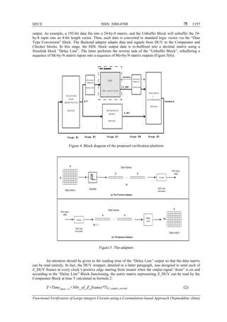
The rest of the paper is organised as follows, section 2 details the proposed platform where the
verification structure, data transformation across stages and the process of settings and controlling the
platform are explained. In section 3, a detailed testcase is given to illustrate the working of the platform
followed by results and discussion. Finally, a conclusion with future works ends the paper.
2. THE PROPOSED PLATFORM
2.1. Overview
The design methodology of the platform follows the Simulation-based approach, where stimuli are
generated, applied to the DUV and responses are compared to the expected ones. Typical verification
framework based on high level design language includes a stimuli generator, a Reference model (also
referred to as Golden Model) which is usually written at a higher level of abstraction, and a comparator. We
abstract the functional description of the platform into three flows, i.e., control flow, data flow and](https://image.slidesharecdn.com/v5926apr1728nov1613503-31086-1-ed-201021061213/85/Functional-Verification-of-Large-integers-Circuits-using-a-Cosimulation-based-Approach-2-320.jpg)
![ ISSN: 2088-8708
IJECE Vol. 7, No. 4, August 2017 : 2192 – 2205
2194
verification flow, as shown in Figure 1. The Control flow controls the process of verification through the
platform. It fixes the settings; i.e. the parameters of the blocks constituting the platform, delay times,
sampling times, etc. Data flow represents the transformations that data undergoes, starting from the
generation of large-integer operands, passing through the input adapter, the DUV, the output adapter and,
finally, entering the comparison/checking blocks. The third flow, Verification flow, verifies the functional
correctness of the DUV. We chose to build the verification flow around two complementary simulation-
based verification approaches: testbench and assertion-based verification. We guide the testbench via a
verification structure with considerations of a coverage plan. When testbench is launched, outputs of DUV
and reference model are compared. Results are then transferred to a Scoreboard to be analyzed. We write
assertions in Property Specification Language (PSL) [24], standard assertion language, inside the DUV and
represent a precise description of the DUV‘s behavior. Note that we chose PSL for property description as
it‗s in widespread use in industry and compatible with many hardware description languages. PSL assertions
are checked by the HDL simulator during the simulation. The assertions verification results (pass/fail) are
also sent to the scoreboard to be analyzed and new stimuli are generated in the next testbench according to
the updated functional coverage.
Figure 1. Functional Description of the platform.
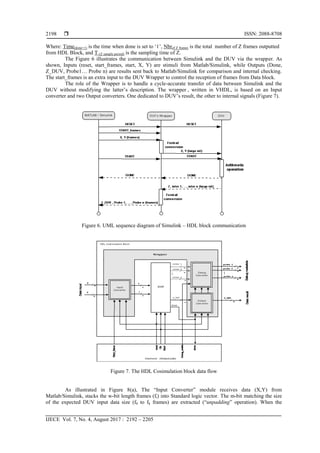
2.2. The Functional Verification Process
The purpose of the ―Functional‖ verification process is to verify that the DUV matches its
specification. This process should verify that the implemented functions behave correctly. The verification
technology used is the simulation-based verification, more precisely a cosimulation between
Matlab/Simulink and ModelSim, and simulated assertions written in PSL.
Globally, we followed a coverage-driven random-based verification approach. The level of
verification can be of unit/sub-unit or cores/blocks level and two simulation-based verification techniques are
used jointly, depending on the partition of DUV being verified. In fact, a common practice in the integrated
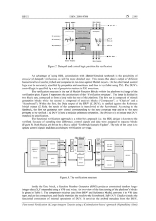
circuits design community is to divide designs into datapath and control logic (Figure 2). Because of their
differences, appropriate verification schemes can be applied to each. Datapath units which involve large-
integers processing can be verified using the Matlab/Simulink testbench where large-integers are supported
as will be detailed in the next section. Datapath usually consists of uniform arrays of cells, such as bits in a
register file, slices in an adder and so on. The remaining logic is regarded as control logic.](https://image.slidesharecdn.com/v5926apr1728nov1613503-31086-1-ed-201021061213/85/Functional-Verification-of-Large-integers-Circuits-using-a-Cosimulation-based-Approach-3-320.jpg)
![IJECE ISSN: 2088-8708
Functional Verification of Large-integers Circuits using a Cosimulation-based Approach (Nejmeddine Alimi)
2201
Figure 10. Verification Platform with FPGA-in-the-loop
Table 3. Comparison with similar verification platforms
Verification
environment
HW Verification
Language (HVL)
Supported
HDL
Interfacing with
Simulator
Cosimulation with
VHDL simulator
Large-integer
support
DUV in
Hardware
[13] C VHDL FLI Yes Limited No
[14] Python VHDL/Verilog FLI/VPI Yes Limited No
[15] Python Verilog VPI No Limited No
[25] Python Verilog VPI No Limited No
[26] Ruby Verilog VPI No Limited No
This Work Matlab/Simulink VHDL/Verilog
HDL Verifier®
+ Wrapper
Yes Unlimited Yes (HIL)
VPI : Verilog Procedural Interface, FLI : Foreign Language Interface,
PLI : Procedural Language Interface , HIL : Hardware-in-the-loop.
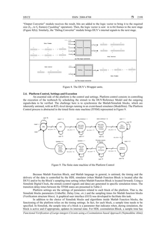
3. CASE STUDY & RESULTS
As case study of the platform, we consider the operation Z = f(X,Y) , where X, Y and Z are three
large-integers. Control signals are reset and start, while Done is an output indicating the end of the operation.
The goal is to evaluate the cost of the bit-size, the number of assertions and the internal signal probing on the
platform.
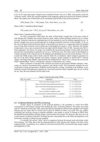
3.1. Large-integer Arithmetic Background
Large-integer arithmetic has a variety of applications in cryptography. Among these, AES, RSA and
ECC. As illustrated in the Figure 11, ECC schemes are based on Point operations, primarily on the point
multiplication and also on the operations on which it point multiplication relies, i.e. point addition and
doubling. In turn, those point operations are made on finite-fields arithmetic, a particular field of large-
integers. This implies that finite-field arithmetic are determinant to design an efficient elliptic curve
cryptosystem. Finite-field arithmetic is the arithmetic of integers modulo a large prime p. Arithmetic in a
finite-field is different from standard integer arithmetic and all operations performed in the finite-field result
in an element within that field. Three kinds of fields that are used for efficient implementation of ECC
systems are prime fields (Fp), binary fields (F2
m
), and optimal extension fields (Fp
m
). Those fields were
extensively studied and this has resulted in numerous algorithms. Finite-field arithmetic is a practical
example of large-integer arithmetic usage and is the cornerstone of cryptographic schemes such as ECC.](https://image.slidesharecdn.com/v5926apr1728nov1613503-31086-1-ed-201021061213/85/Functional-Verification-of-Large-integers-Circuits-using-a-Cosimulation-based-Approach-10-320.jpg)
![ ISSN: 2088-8708
IJECE Vol. 7, No. 4, August 2017 : 2192 – 2205
2202
Figure 11. Hierarchy of required underlying operations
3.2. The DUV
A hardware implementation of a Finite-field multiplication algorithm called the ―Double, add, and
reduce‖ (DAR) multiplier [27] was used as a DUV. The DAR multiplier is based on the Interleaving
Multiplication Algorithm [28]. Given a k-bit natural x and a natural y the product z = x . y can be computed
as follows formula 6:
x.y = (xk-1 2k-1
+ xk-2 2k-2
+ … +x0 20
).y (6)
The latter can also be expressed as in formula 7:
x.y = (… ((0.2+ xk-1 y )2+ xk-2 y)2+…+ x1y)2+x0y (7)
If all operations (addition and doubling) are executed mod m, the result is product = x .y mod m.
The corresponding (left to right) algorithm, written in ADA syntax, is presented in Listing 1. The function
―mod_m_addition(x, y, m, k)‖ computes x + y mod m ; x, y, and m being k-bit numbers, according to the
binary mod m Addition. This unit of the datapath represents an internal large-integer operation. In the design,
operands were set to recommended sizes (192, 384, 512, 1024) for cryptographic use by the NIST [29].
Listing 1 Double, add, and reduce (DAR) algorithm.
p := 0 ;
for i in 0 .. k-1 loop
p := mod_m_addition(p, p, m, k);
if x(k-i-1) = 1 then
p := mod_m_addition(p, y, m, k);
end if;
end loop;
product := p;
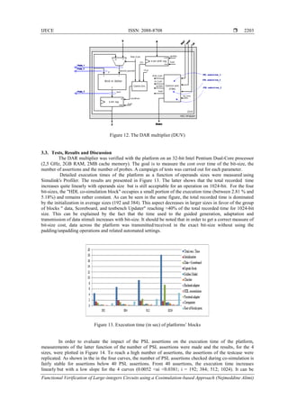
The datapath and a part of control logic corresponding to the hardware description of Algorithm 1
are shown in Figure 12. The DUV is an ideal case for the platform testing with internal large-integer
operation and a distinct control units and datapath. In practice, in addition to the functional validation
(comparing DUV against reference model), each partition modules were verified. For datapath, ―Mod m
Adder‖ module was the target of internal checking while the control logic units were verified with PSL
assertions.](https://image.slidesharecdn.com/v5926apr1728nov1613503-31086-1-ed-201021061213/85/Functional-Verification-of-Large-integers-Circuits-using-a-Cosimulation-based-Approach-11-320.jpg)
![ ISSN: 2088-8708
IJECE Vol. 7, No. 4, August 2017 : 2192 – 2205
2204
concluded that the PSL assertions increase the execution time but the more the number gets larger (> 100),
the more the impact on time is limited. It should be noted that the ―steep slope‖ aspect of the curve is due to
the high steps taken, on the horizontal axis, from the 200th
assertion.
To evaluate the impact of the number of Probes on the execution time, measurements of the
platform time for a fixed DUV bit-size (1024 bit) function of the number of probes were made and the results
are shown in Figure 15. In this test, the outputs of the "HDL co-simulation" block, the number of sub-blocks
of the "Backend Adapter" stage and the inputs of the "Checker" were adjusted to match the corresponding
number of probes. According to results, when the number of probes increases, the execution time increases
linearly but with a low slope (α ≈ 0.4). It can be said that the number of probes increases the execution time
of the verification process but does not penalize it especially because a small number of probes is generally
needed for verification.
Analysis of the three tests campaign results indicates that the parameters (bit-size, number of
assertions and number of probes) has only a moderate impact on the execution time of the verification
platform, thus justifying its efficiency.
Figure 14. Platform's execution time (in sec) as a
function of PSL assertions
Figure 15. Execution Time (in sec) as a function of
number of probes
4. CONCLUSION
In this paper, we have presented a novel platform intended to verify hardware large-integer based
designs, the first one based on Matlab/Simulink to the best of our knowledge. We demonstrated that the
proposed platform holds a number of interesting aspects for the task of verification. First, this is run time and
cycle-accurate verification. Second, flexibility, where minor adjustments in Matlab/Simulink blocks
parameters, different bit-length can be verified with a moderate impact on execution time. Besides, testbench
scenarios are adjustable to meet desired verification coverage where datapath and control logic can be
verified simultaneously and in different level of the design hierarchy. Third, reusability: In this paper, we
developed testcase on finite-field arithmetic but we also tested the platform to verify a scalar multiplication
(Figure 11) this proves that the platform is adapted to more complex systems like cryptographic primitives.
Future work will involve improvements like reducing synchronisation and data transfer overhead,
limiting the complexity of the wrapping module, and enabling internal verification in HIL. Furthermore, an
interesting area of application of the platform that would need further efforts is the verification of designs
under development, with possibility of replacing unachieved blocks with equivalent Matlab/Simulink
models. Another extension of the platform, in the field of cryptanalysis, could be using Matlab‘s data
processing features to verify design robustness to side-channel and fault injection attacks in HIL.
REFERENCES
[1] R. L. Rivest, A. Shamir, and L. Adleman, ―A method for obtaining digital signatures and public-key
cryptosystems,‖ Communications of the ACM, vol. 21, no. 2, pp. 120–126, Feb. 1978.
[2] Victor S. Miller, ―Use of Elliptic Curves in Cryptography,‖ in Advances in Cryptology — CRYPTO ’85
Proceedings, 1986, vol. 218.
[3] N. Koblitz, ―Elliptic curve cryptosystems,‖ Mathematics of Computation, vol. 48, no. 177, pp. 203–203, Jan. 1987.
[4] Y. Kong, S. Asif, and M. A. U. Khan, ―Modular multiplication using the core function in the residue number
system,‖ Applicable Algebra in Engineering, Communication and Computing, Jul. 2015.
[5] M. T. Hamood and S. Boussakta, ―Efficient algorithms for computing the new Mersenne number transform,‖](https://image.slidesharecdn.com/v5926apr1728nov1613503-31086-1-ed-201021061213/85/Functional-Verification-of-Large-integers-Circuits-using-a-Cosimulation-based-Approach-13-320.jpg)
![IJECE ISSN: 2088-8708
Functional Verification of Large-integers Circuits using a Cosimulation-based Approach (Nejmeddine Alimi)
2205
Digital Signal Processing, vol. 25, pp. 280–288, Feb. 2014.
[6] G. X. Yao, J. Fan, R. C. C. Cheung, and I. Verbauwhede, ―Novel RNS Parameter Selection for Fast Modular
Multiplication,‖ IEEE Transactions on Computers, vol. 63, no. 8, pp. 2099–2105, Aug. 2014.
[7] T. Wu, S. Li, and L. Liu, ―Fast RSA decryption through high-radix scalable Montgomery modular multipliers,‖
Science China Information Sciences, vol. 58, no. 6, pp. 1–16, Mar. 2015.
[8] S. Antão and L. Sousa, ―A Flexible Architecture for Modular Arithmetic Hardware Accelerators based on RNS,‖
Journal of Signal Processing Systems, vol. 76, no. 3, pp. 249–259, 2014.
[9] K. Jarvinen, V. Dimitrov, and R. Azarderakhsh, ―A Generalization of Addition Chains and Fast Inversions in
Binary Fields,‖ IEEE Transactions on Computers, vol. 64, no. 9, pp. 2421–2432, Sep. 2015.
[10] G. D. Sutter, J. Deschamps, and J. L. Imana, ―Efficient Elliptic Curve Point Multiplication Using Digit-Serial
Binary Field Operations,‖ IEEE Transactions on Industrial Electronics, vol. 60, no. 1, pp. 217–225, Jan. 2013.
[11] S. Suma and V. Sridhar, ―Design of Multiplier for Medical Image Compression Using Urdhava Tiryakbhyam
Sutra,‖ International Journal of Electrical and Computer Engineering (IJECE), vol. 6, no. 3, pp. 1140–1151, 2016.
[12] G. Arepalli and S. B. Erukula, ―Secure Multicast Routing Protocol in Manets Using Efficient ECGDH Algorithm,‖
International Journal of Electrical and Computer Engineering (IJECE), vol. 6, no. 4, pp. 1857–1865, 2016.
[13] A. Pool, ―Using ModelSim Foreign Language Interface for C – VHDL Co-Simulation and for Simulator Control on
Linux x86 Platform,‖ 2014.
[14] Potential Ventures, ―cocotb : COroutine based COsimulation TestBench environment for verifying VHDL/Verilog
RTL,‖ 2014.
[15] B. Smith, T. Loftus, J. Greene, and X. Wu, ―PyHVL, a verifcation tool,‖ 2007.
[16] F. Farahmandi and B. Alizadeh, ―Groebner basis based formal verification of large arithmetic circuits using
Gaussian elimination and cone-based polynomial extraction,‖ Microprocessors and Microsystems, vol. 39, no. 2,
pp. 83–96, Mar. 2015.
[17] T. Pruss, P. Kalla, and F. Enescu, ―Efficient Symbolic Computation for Word-Level Abstraction From
Combinational Circuits for Verification Over Finite Fields,‖ IEEE Transactions on Computer-Aided Design of
Integrated Circuits and Systems, vol. 35, no. 7, pp. 1206–1218, Jul. 2016.
[18] C. Siggaard, ―Using MatLab to aid the implementation of a fast RSA processor on a Xilinx FPGA,‖ in Nordic
MathWorks User Conference, 2008.
[19] D. B. Cousins, K. Rohloff, C. Peikert, and R. Schantz, ―An update on SIPHER (Scalable Implementation of
Primitives for Homomorphic EncRyption) — FPGA implementation using Simulink,‖ in 2012 IEEE Conference on
High Performance Extreme Computing, 2012, pp. 1–5.
[20] D. Cousins, J. Golusky, K. Rohloff, and D. Sumorok, ―An FPGA Co-Processor Implementation of Homomorphic
Encryption,‖ in 2014 IEEE High Performance Extreme Computing Conference, 2014.
[21] P. C. Realpe, V. Trujillo-Olaya, and J. Velasco-Medina, ―Design of elliptic curve cryptoprocessors over GF(2^163)
using the Gaussian normal basis,‖ Ingeniería e Investigación, vol. 34, no. 2, pp. 55–65, Jul. 2014.
[22] A. Kaleel Rahuman and G. Athisha, ―Reconfigurable Architecture for Elliptic Curve Cryptography Using FPGA,‖
Mathematical Problems in Engineering, vol. 2013, pp. 1–8, 2013.
[23] N. Alimi, Y. Lahbib, M. Machhout, and R. Tourki, ―Simulation-based verification of large-integer arithmetic
circuits,‖ in 2016 1st IEEE International Verification and Security Workshop, IVSW 2016, 2016, pp. 19–24.
[24] Accellera, ―Property Specification Language Reference Manual.‖ 2004.
[25] Decaluwe and Jan, ―MyHDL: a Python-based hardware description language,‖ Linux Journal, no. 127, p. 5, 2004.
[26] S. N. Kurapati, ―Specification-driven functional verification with Verilog PLI & VPI and SystemVerilog DPI,‖
2007.
[27] J.-P. Deschamps, Hardware Implementation of Finite-Field Arithmetic. McGraw Hill Professional, 2009.
[28] F. Rodriguez-Henriquez, N. A. Saqib, A. D. Pérez, and C. K. Koc, Cryptographic Algorithms on Reconfigurable
Hardware. Springer Science & Business Media, 2007.
[29] E. Barker, W. Barker, W. Burr, W. Polk, and M. Smid, ―NIST Special Publication 800-57, Recommendation for
Key Management Part 1: General (Revision 3),‖ 2012.](https://image.slidesharecdn.com/v5926apr1728nov1613503-31086-1-ed-201021061213/85/Functional-Verification-of-Large-integers-Circuits-using-a-Cosimulation-based-Approach-14-320.jpg)