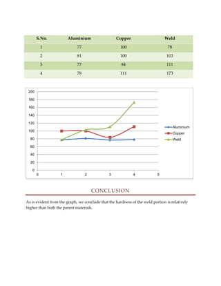
Downloaded 110 times

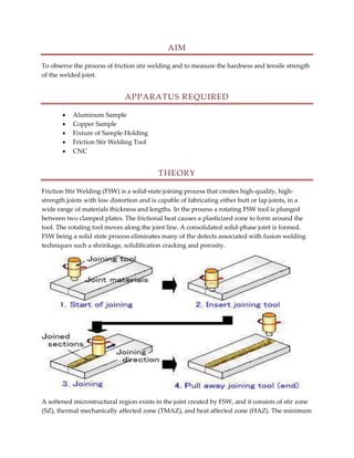

The document discusses friction stir welding (FSW), which uses a rotating tool to plastically join two metal surfaces without melting them. Students conducted an experiment using FSW to join aluminum and copper samples. They measured the hardness of the original and welded metals. The welded portions were found to be harder than the parent materials. FSW produces high-quality welds for applications like shipbuilding and aerospace with advantages of low distortion, excellent mechanical properties, and no porosity compared to fusion welding.