This document provides an overview of friction stir welding (FSW), including its principles, setup, materials used, advantages, and applications. Some key points:
- FSW was invented in 1991 as a solid-state welding process that generates frictional heat between a rotating tool and materials to join them below their melting points.
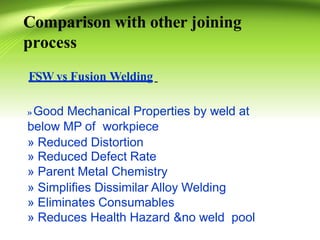
- It overcomes issues with conventional welding like distortion and defects, and allows welding of materials like aluminum alloys.
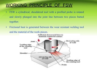
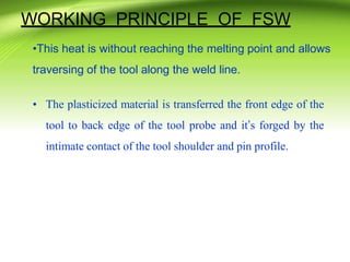
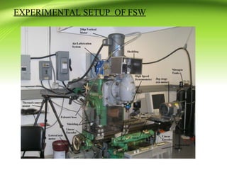
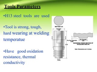
- The FSW setup involves a cylindrical, shouldered tool that is plunged into and traverses along the joint line. This generates frictional heat to plasticize the materials and forge them together.
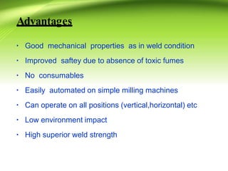
- FSW produces high strength welds in applications like
![REFERENCES
[1].M. Jeyaraman, R. Sivasubramanian, V .Balasubramanian “Optimization of process
parameters forfrictionstirweldingof cast aluminiuma loyA319 byTaguchi method”.
Journal of material processing technology 2 0 0 (2008)364–372 .
[2].P. Hema, S.M. Gangadhar, K. Ravindranath, “Optimization of Process Parametersfor
FrictionStirWeldingof AluminiumA loy6061usingANOVA”. International Journal of
Mechanical and Production Engineering,Vol.2, Issue 1 (2012) 36-42.
[3] L.Dubourg, A.Merati, M.Jahazi, “Process optimization and mechanical properties of
friction stir lap welds of7075-T6stringerson2024-T3skin”. The Journal of Materials and
design31 (2010) 3324–3330.](https://image.slidesharecdn.com/friction-stir-welding2-130906104920-1-230813180104-b1892225/85/friction-stir-welding2-130906104920-1-pptx-25-320.jpg)