The document analyzes potential energy optimization opportunities for a vessel called the ASD-2810 through heat recovery. It begins with an introduction and overview of the research contents. Next, it performs a vessel analysis which examines the vessel's energy demands and waste heat supply sources. It then reviews various heat recovery technology options for heat, cooling, freshwater and electric supply. An example heat recovery scheme is presented and its potential fuel savings are analyzed for different system configurations and seasons. Key conclusions are that storage systems are important for continuous supply and an adsorption-based system using heat storage provides the largest fuel savings. A recommendation is made to develop a heat recovery optimization tool to help evaluate different component options.
![Introduction Vessel analysis Heat recovery
technologies
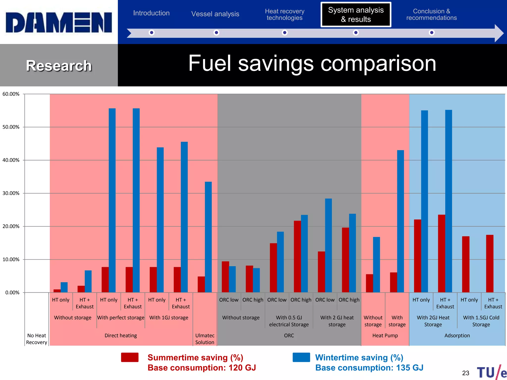
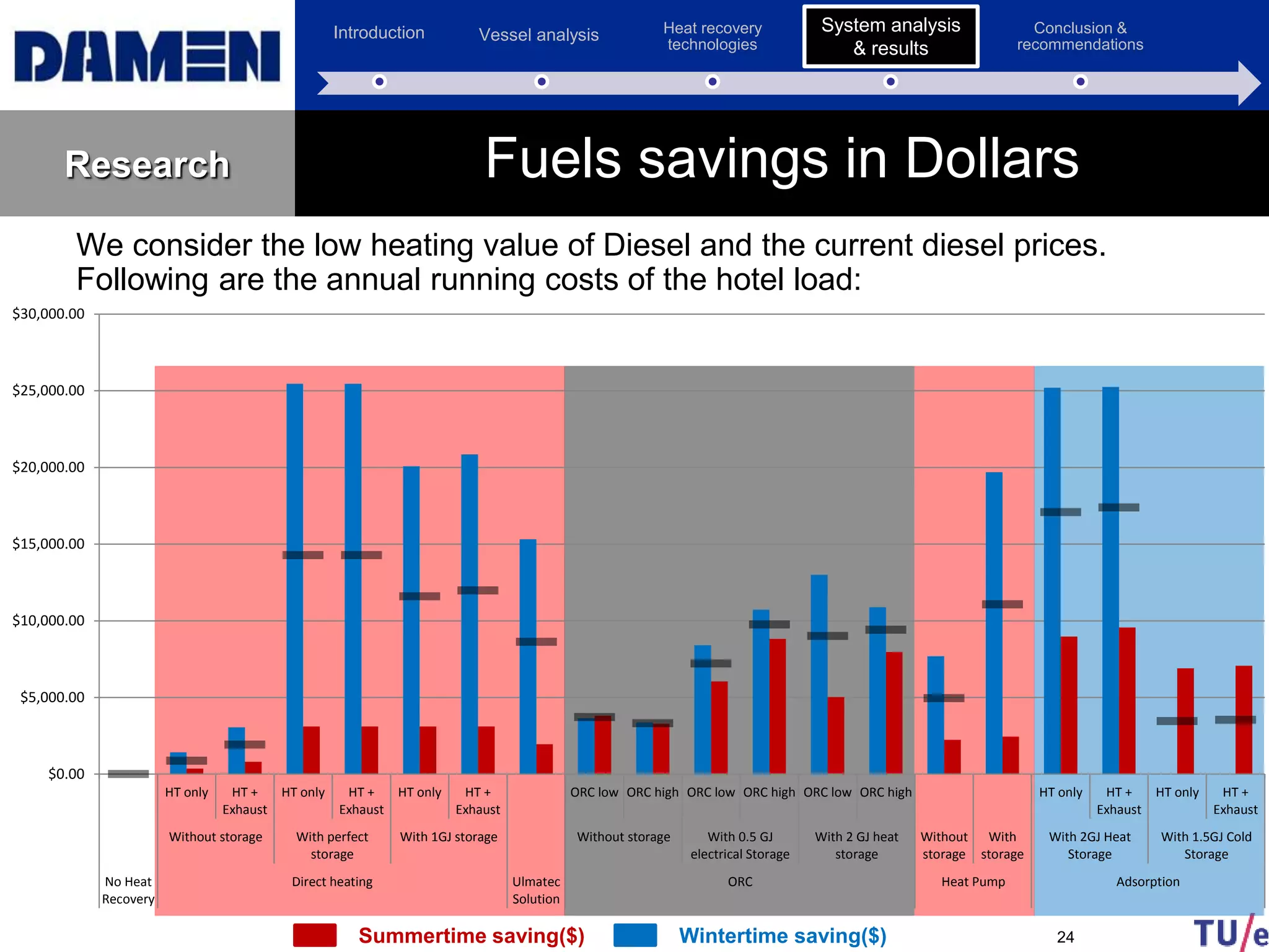
System analysis &
results
Conclusion &
recommendations
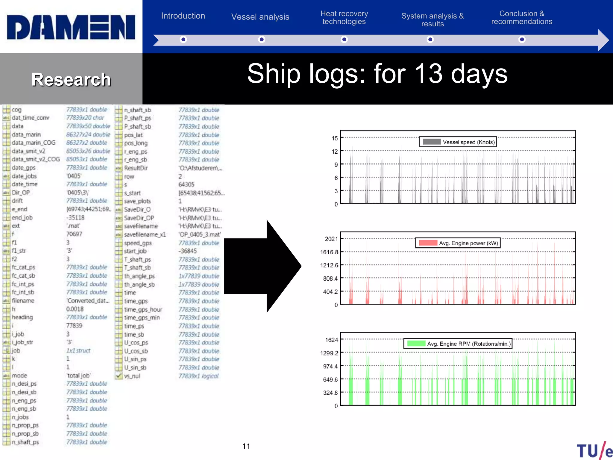
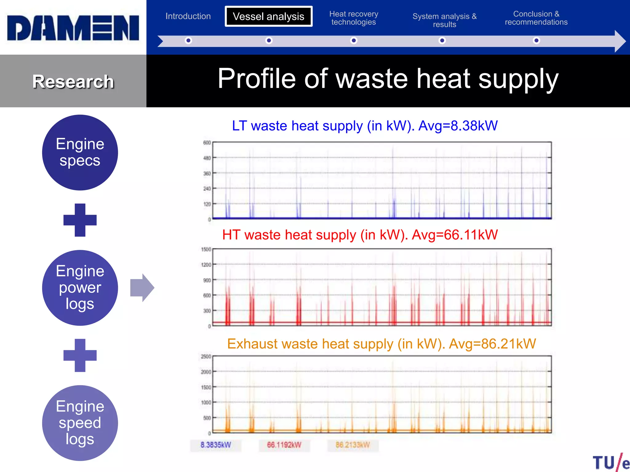
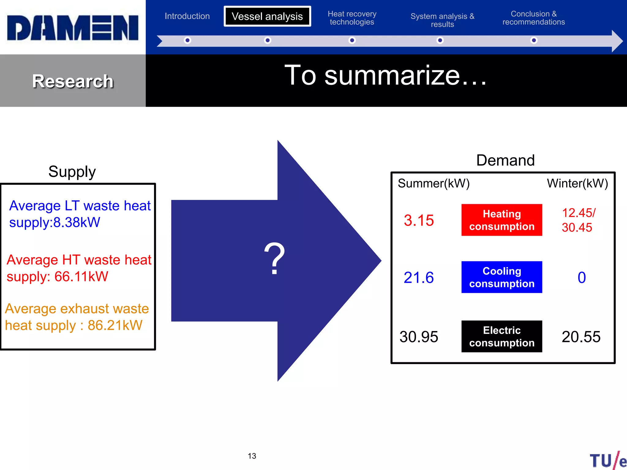
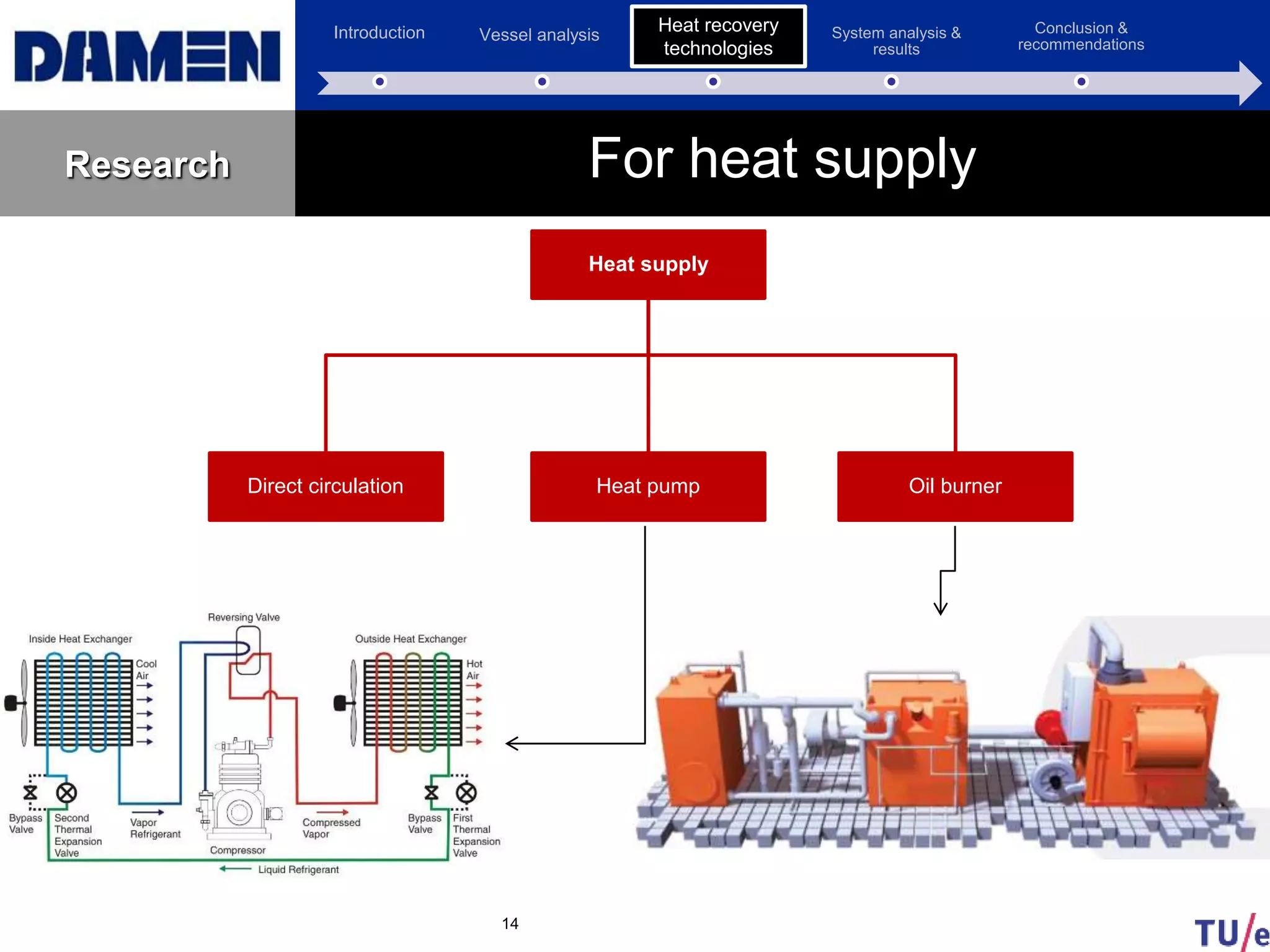
Research
6
Propulsion and electrical generation systems
Propulsion
Engine
3516-C
1864 kW @ 1600RPM
G
B
G
B
G
86 ekW
DE
93 bkW
G
86 ekW
DE
93 bkW
[440V,60Hz]SwitchBoard
Hotel load
Propulsion
Engine
3516-C
1864 kW @ 1600RPM
Introduction](https://image.slidesharecdn.com/370dc321-cbb1-4e23-93bf-8523035d90fe-151230133621/75/Friday-presentation-6-2048.jpg)