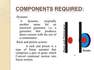
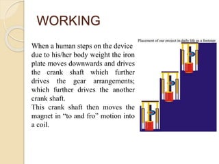
FOOT STEP POWER
GENERATION
 For an alternative method to generate
electricity there are number of methods by
which electricity can be produced.
 Out of such methods, foot step energy
generation can be an effective method to
generate electricity.
Dynamo:
A dynamo, originally
another name for an
electrical generator, i.e, a
generator that produces
direct current with the use of
a commutator.
Rack and pinion system:
A rack and pinion is a
type of linear actuator that
comprises a pair of gears which
Convert rotational motion into
linear motion.
3. Rotary Converter
Development:
Used to develop
complex
multi-field single-rotor
devices with two or
more
commutators.These
were known as a rotary
converter.
LITERATURE REVIEW
An Investigation on Generation of Electricity Using Foot Step
Nowadays energy and power are the one of the basic necessities
regarding this modern world. As the demand of energy is
increasing day by day, so the ultimate solution to deal with these
sorts of problems is just to implement the renewable sources of
energy.
But these renewable energy sources must have to be adopted in
practical manner by keeping an eye on all aspects regarding the
research work. So then these techniques should be applied in
order to get the desired output.
The objective of this work is power generation through footsteps
as a source of renewable energy that we can obtained while
walking on to the certain arrangements like footpaths, stairs, plate
forms and these systems can be install elsewhere specially in the
dense populated areas.
Electromagnetic Foot Step Power Generation
The main aim of this project is to develop much cleaner
cost effective way of power generation method, which in
turns helps to bring down the global warming as well as
reduce the power shortages.
In this project the conversion of the force energy in to
electrical energy by using electromagnetic induction.
In this project the force energy is converted into
electrical energy.
The control mechanism carries the copper coil and bar
magnetic which is used to generate voltage, a
rechargeable battery is used to store this generated
voltage.
WORKING
When a human steps on the device
due to his/her body weight the iron
plate moves downwards and drives
the crank shaft which further
drives the gear arrangements;
which further drives the another
crank shaft.
This crank shaft then moves the
magnet in “to and fro” motion into
a coil.
SCHEMATIC DIAGRAM
ASSEMBLY DIAGRAM
COMPONENTS
1. MS plate
The Mild steel plate is a square plate of size 1feet*1 feet
i.e. 300 mm*300 mm.
The thickness of the plate is 3mm.
We are using two plates here one base plate and one upper
plate to place foot.
2. Pipes
There two types of cylindrical Mild Steel pipes are used.
One is for bottom plate of diameter 30 mm and
thickness of 3 mm which contains spring placed into it,
while other pipe is welded to upper plate of diameter 20
mm, and of thickness 3 mm.
The length of both the pipes is 100 mm.
3. Pinion
1. SPECIFICATION OF PINION
2. Material : aluminium
3. Outside diameter : 30 mm
4. Module: 1.5
5. Pitch circle diameter: 27.5 mm
6. Addendum : 1.5mm
7. Dedendum : 1.875mm
8. Gear width : 5 mm
4. RACK
 SPECIFICATION OF RACK
 Material : cast iron
 Module : 1.5mm
 Cross-section :5*4 mm
 Teeth on the rack is adjusted for 115 mm.
5. DC motor
 Product Description:
 Center Shaft Geared motors specifically designed for
robotic applications offer a wide variety of options.
 Key features – easy to use and mount, standard size for
all RPM’s, a huge variety of RPM’s available, long
durability and very affordable considering the features.
 These motors open a wide choice for you in terms of
Wheels and chassis.
Specifications –
RPM – 60
Shaft Diameter – 6mm (with internal hole)
Weight - 125gms
Torque – 6kgcm
Voltage – 6 to 24 (Nominal Voltage – 12v)
No-load current = 60 mA (Max),
Load current= 300 mA (Max)
COST ESTIMATION
SR NO. COMPONENT DETAILS COST IN RS.
1. Base and upper plate Mild steel -300*300 mm
(300*2)
600
2. Fixed Cylindrical pipes MS pipes, 30 mm dia.-
100 mm length (200*4)
800
3. Moving pipes MS pipes ,20 mm dia.
100 mm length (200*4)
800
4. Springs Alloy Steel Wire(200*4) 800
5. Rack and pinion Cast iron, module 1.5 800
6. DC motor 12 volt, 60 rpm 250
7. fabrication Cutting , welding etc. 2000
8. Assembly Mounting, fixing motor
shaft with pinion.
Adjusting rack and
pinion etc. and final
welding
1100
9. Others - 1000
Total 8150 /-
ADVANTAGES
 Power generation is simply walking on
the step
 Power also generated by running or
exercising on the step.
 No need fuel input
 This is a Non-conventional system
 Battery is used to store the generated
power
APPLICATIONS
 Applications of the foot step power
generation are,
 This can be implemented on railway
station to generate electric power.
 In bus station.
 In car parking system.
 In Airports.
 In Lift system.
 In car lifting system.
 In street lights
 Electric escalators
FUTURE SCOPE :
 We can use this principal in the speed breakers at
high ways , where the vehicles rush too much, thus
increase input torque and ultimate output of
generator.
 By increasing the size and multiplying the frequency
of array of system we can build a big power option
for domestic and public use.
 If we use this project at very busy stairs , then we
produce efficient useful electrical energy for large
purposes .
 The design of the project can be further modified for
commercial and large scale use.
CONCLUSION
 In concluding the words of our project, since
the power generation using foot step get its
energy requirements from the Non-renewable
source of energy.
 There is no need of power from the mains
and there is less pollution in this source of
energy.
 It is very useful to the places all roads and as
well as all kind of foot step which is used to
generate the non-conventional energy like
electricity.
 It is able to extend this project by using same
arrangement and construct in the
footsteps/speed breaker so that increase the
power production rate by fixing school and
REFERENCES
 RAI. G.D. “NON CONVENTIONAL ENERGY SOURCES”, KHANNA PUBLISHERS, DELHI.
 RAMESH. R, UDAYA KUMAR, K.ANANDAKRISHNAN “RENEWABLE ENERGY
TECHNOLOGIES”, NAROSA PUBLISHING HOUSE, MADRAS.
 A.K.SAWHNEY. “A TEXT BOOK OF ELECTRICAL, ELECTRONICS, INSTRUMENTATION
AND MEASUREMENTS”
 B.L.THERJA, A.K. THERAJA. “A TEXT BOOK OF ELECTRICAL TECHNOLOGY”
 G.R.NAGPAL. “POWER PLANT ENGINEERING” KHANNA PUBLISHERS, DELHI.
 T.NEJAT VEZIROYGAL , ALTERNATIVE ENERGY SOURCES-III, HEMISPHERE
PUBLISHING CO.,
 BARBARA KEILER, ENERGY ALTERNATIVES, LUSCENTR BOOKS.
 PRABHU T.J. FUNDAMENTALS OF MACHINES DESIGN,2009
 DESIGN DATA, PSG COLLEGE OF TECHNOLOGY,2007
 BHANDARI V.B. “DESIGN OF MACHINE ELEMENTS”- TATA MCGRAW HILL,2007
 SHIGLEY J.E. AND MISHEKA “MECHANICAL ENGINEERING DESIGN”MCGRAW HILL,2007
 PANDYA AND SHAH “ELEMENTS OF MACHINES DESIGN ”,2000
 MAITRA, HANDBOOK OF GEAR DESIGN,TATA MCGRAW HILL,199
 GERE TIMOSHENKO “MECHANICS OF MATERIALS” CBS,1997.
THANK YOU

foot step power generation final ppt.pptx

  • 1.
  • 2.
     For analternative method to generate electricity there are number of methods by which electricity can be produced.  Out of such methods, foot step energy generation can be an effective method to generate electricity.
  • 3.
    Dynamo: A dynamo, originally anothername for an electrical generator, i.e, a generator that produces direct current with the use of a commutator. Rack and pinion system: A rack and pinion is a type of linear actuator that comprises a pair of gears which Convert rotational motion into linear motion.
  • 4.
    3. Rotary Converter Development: Usedto develop complex multi-field single-rotor devices with two or more commutators.These were known as a rotary converter.
  • 5.
    LITERATURE REVIEW An Investigationon Generation of Electricity Using Foot Step Nowadays energy and power are the one of the basic necessities regarding this modern world. As the demand of energy is increasing day by day, so the ultimate solution to deal with these sorts of problems is just to implement the renewable sources of energy. But these renewable energy sources must have to be adopted in practical manner by keeping an eye on all aspects regarding the research work. So then these techniques should be applied in order to get the desired output. The objective of this work is power generation through footsteps as a source of renewable energy that we can obtained while walking on to the certain arrangements like footpaths, stairs, plate forms and these systems can be install elsewhere specially in the dense populated areas.
  • 6.
    Electromagnetic Foot StepPower Generation The main aim of this project is to develop much cleaner cost effective way of power generation method, which in turns helps to bring down the global warming as well as reduce the power shortages. In this project the conversion of the force energy in to electrical energy by using electromagnetic induction. In this project the force energy is converted into electrical energy. The control mechanism carries the copper coil and bar magnetic which is used to generate voltage, a rechargeable battery is used to store this generated voltage.
  • 7.
    WORKING When a humansteps on the device due to his/her body weight the iron plate moves downwards and drives the crank shaft which further drives the gear arrangements; which further drives the another crank shaft. This crank shaft then moves the magnet in “to and fro” motion into a coil.
  • 8.
  • 9.
  • 10.
    COMPONENTS 1. MS plate TheMild steel plate is a square plate of size 1feet*1 feet i.e. 300 mm*300 mm. The thickness of the plate is 3mm. We are using two plates here one base plate and one upper plate to place foot.
  • 11.
    2. Pipes There twotypes of cylindrical Mild Steel pipes are used. One is for bottom plate of diameter 30 mm and thickness of 3 mm which contains spring placed into it, while other pipe is welded to upper plate of diameter 20 mm, and of thickness 3 mm. The length of both the pipes is 100 mm.
  • 12.
    3. Pinion 1. SPECIFICATIONOF PINION 2. Material : aluminium 3. Outside diameter : 30 mm 4. Module: 1.5 5. Pitch circle diameter: 27.5 mm 6. Addendum : 1.5mm 7. Dedendum : 1.875mm 8. Gear width : 5 mm
  • 13.
    4. RACK  SPECIFICATIONOF RACK  Material : cast iron  Module : 1.5mm  Cross-section :5*4 mm  Teeth on the rack is adjusted for 115 mm.
  • 14.
    5. DC motor Product Description:  Center Shaft Geared motors specifically designed for robotic applications offer a wide variety of options.  Key features – easy to use and mount, standard size for all RPM’s, a huge variety of RPM’s available, long durability and very affordable considering the features.  These motors open a wide choice for you in terms of Wheels and chassis.
  • 15.
    Specifications – RPM –60 Shaft Diameter – 6mm (with internal hole) Weight - 125gms Torque – 6kgcm Voltage – 6 to 24 (Nominal Voltage – 12v) No-load current = 60 mA (Max), Load current= 300 mA (Max)
  • 16.
    COST ESTIMATION SR NO.COMPONENT DETAILS COST IN RS. 1. Base and upper plate Mild steel -300*300 mm (300*2) 600 2. Fixed Cylindrical pipes MS pipes, 30 mm dia.- 100 mm length (200*4) 800 3. Moving pipes MS pipes ,20 mm dia. 100 mm length (200*4) 800 4. Springs Alloy Steel Wire(200*4) 800 5. Rack and pinion Cast iron, module 1.5 800 6. DC motor 12 volt, 60 rpm 250 7. fabrication Cutting , welding etc. 2000 8. Assembly Mounting, fixing motor shaft with pinion. Adjusting rack and pinion etc. and final welding 1100 9. Others - 1000 Total 8150 /-
  • 17.
    ADVANTAGES  Power generationis simply walking on the step  Power also generated by running or exercising on the step.  No need fuel input  This is a Non-conventional system  Battery is used to store the generated power
  • 18.
    APPLICATIONS  Applications ofthe foot step power generation are,  This can be implemented on railway station to generate electric power.  In bus station.  In car parking system.  In Airports.  In Lift system.  In car lifting system.  In street lights  Electric escalators
  • 19.
    FUTURE SCOPE : We can use this principal in the speed breakers at high ways , where the vehicles rush too much, thus increase input torque and ultimate output of generator.  By increasing the size and multiplying the frequency of array of system we can build a big power option for domestic and public use.  If we use this project at very busy stairs , then we produce efficient useful electrical energy for large purposes .  The design of the project can be further modified for commercial and large scale use.
  • 20.
    CONCLUSION  In concludingthe words of our project, since the power generation using foot step get its energy requirements from the Non-renewable source of energy.  There is no need of power from the mains and there is less pollution in this source of energy.  It is very useful to the places all roads and as well as all kind of foot step which is used to generate the non-conventional energy like electricity.  It is able to extend this project by using same arrangement and construct in the footsteps/speed breaker so that increase the power production rate by fixing school and
  • 21.
    REFERENCES  RAI. G.D.“NON CONVENTIONAL ENERGY SOURCES”, KHANNA PUBLISHERS, DELHI.  RAMESH. R, UDAYA KUMAR, K.ANANDAKRISHNAN “RENEWABLE ENERGY TECHNOLOGIES”, NAROSA PUBLISHING HOUSE, MADRAS.  A.K.SAWHNEY. “A TEXT BOOK OF ELECTRICAL, ELECTRONICS, INSTRUMENTATION AND MEASUREMENTS”  B.L.THERJA, A.K. THERAJA. “A TEXT BOOK OF ELECTRICAL TECHNOLOGY”  G.R.NAGPAL. “POWER PLANT ENGINEERING” KHANNA PUBLISHERS, DELHI.  T.NEJAT VEZIROYGAL , ALTERNATIVE ENERGY SOURCES-III, HEMISPHERE PUBLISHING CO.,  BARBARA KEILER, ENERGY ALTERNATIVES, LUSCENTR BOOKS.  PRABHU T.J. FUNDAMENTALS OF MACHINES DESIGN,2009  DESIGN DATA, PSG COLLEGE OF TECHNOLOGY,2007  BHANDARI V.B. “DESIGN OF MACHINE ELEMENTS”- TATA MCGRAW HILL,2007  SHIGLEY J.E. AND MISHEKA “MECHANICAL ENGINEERING DESIGN”MCGRAW HILL,2007  PANDYA AND SHAH “ELEMENTS OF MACHINES DESIGN ”,2000  MAITRA, HANDBOOK OF GEAR DESIGN,TATA MCGRAW HILL,199  GERE TIMOSHENKO “MECHANICS OF MATERIALS” CBS,1997.
  • 22.