Downloaded 112 times

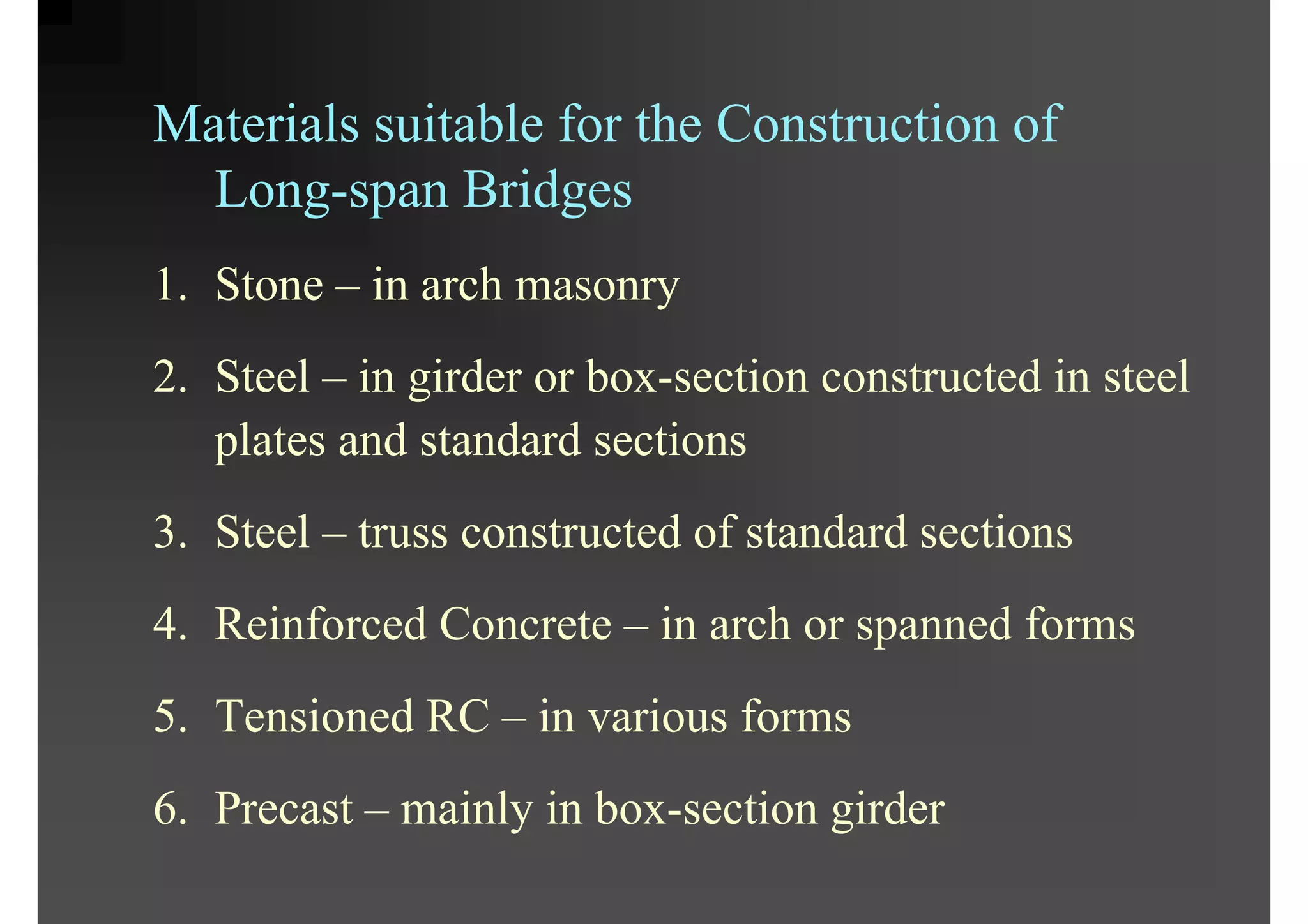


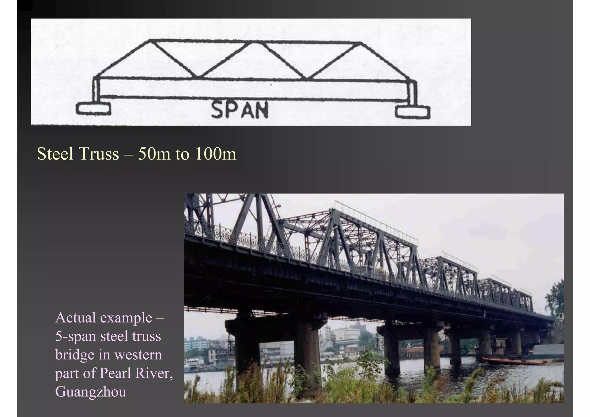
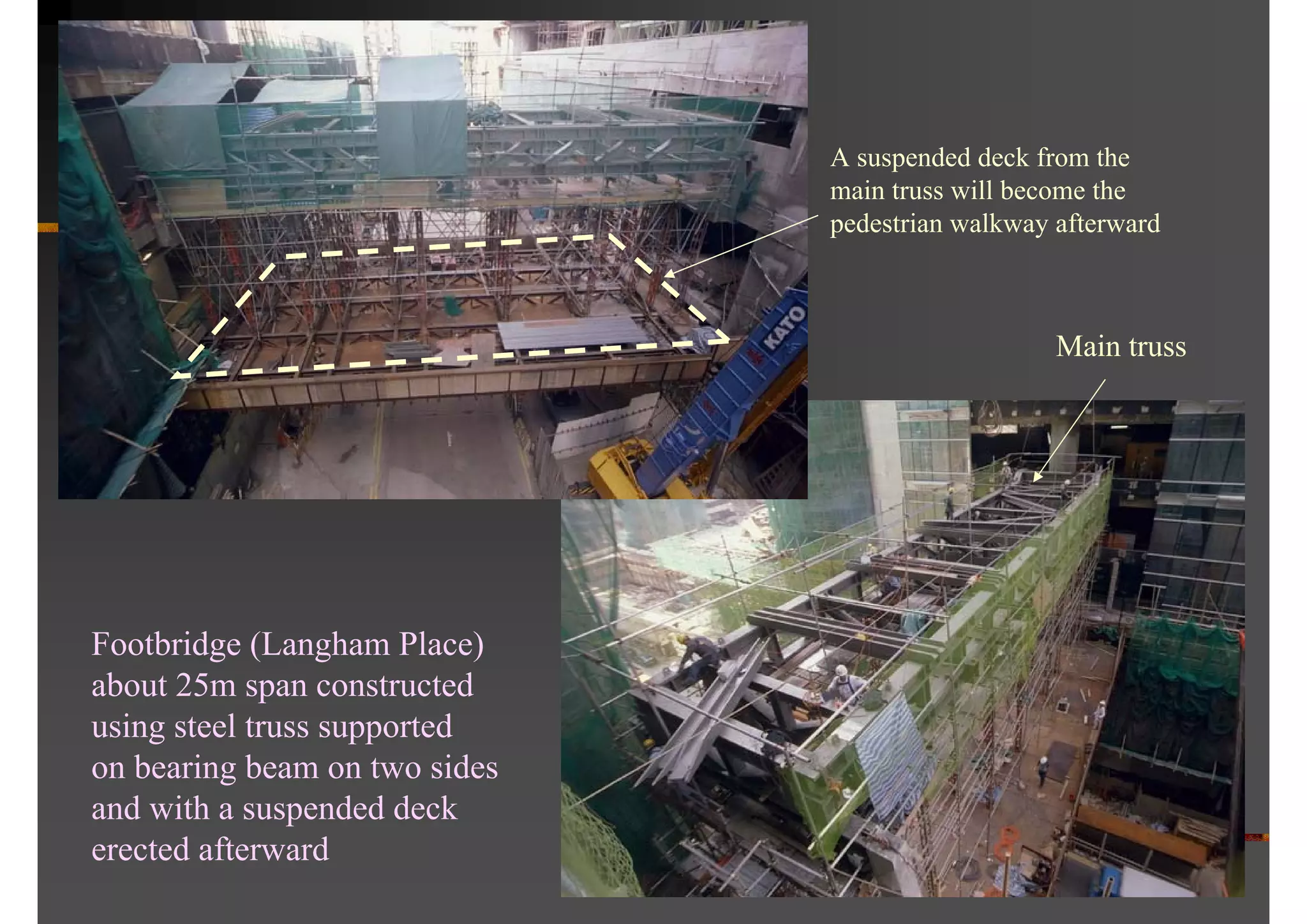

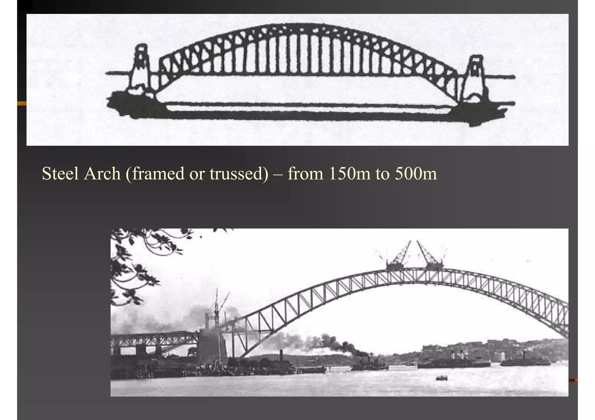
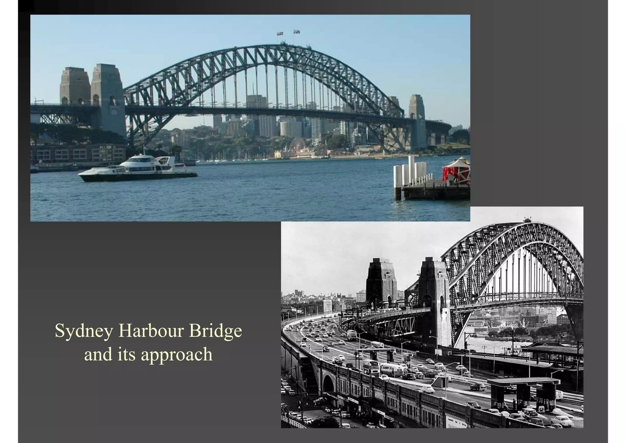


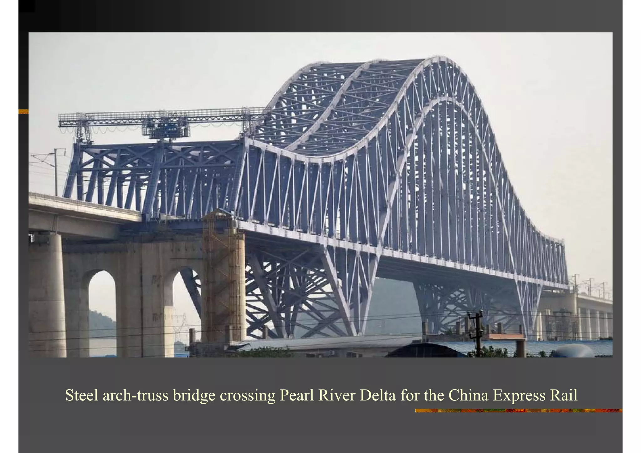
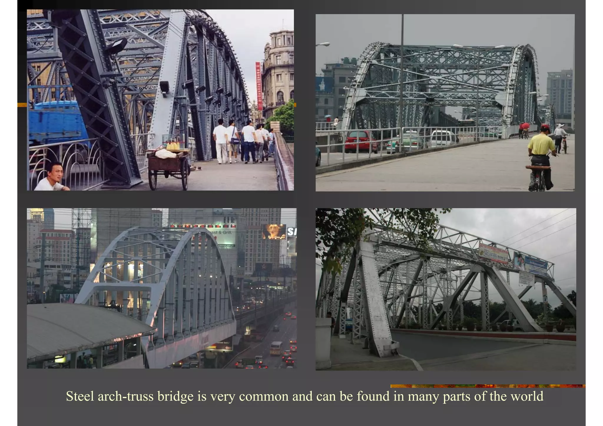
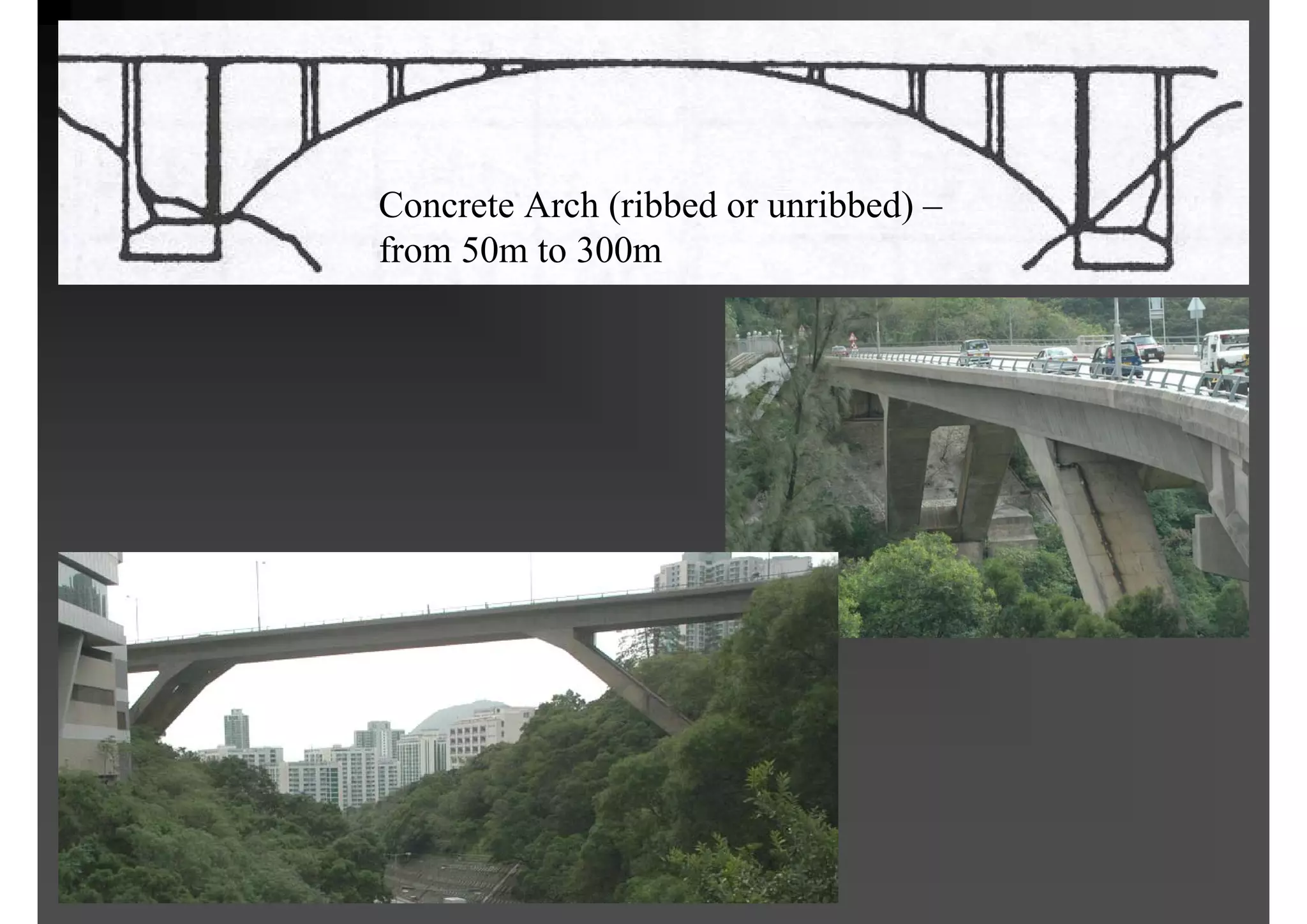
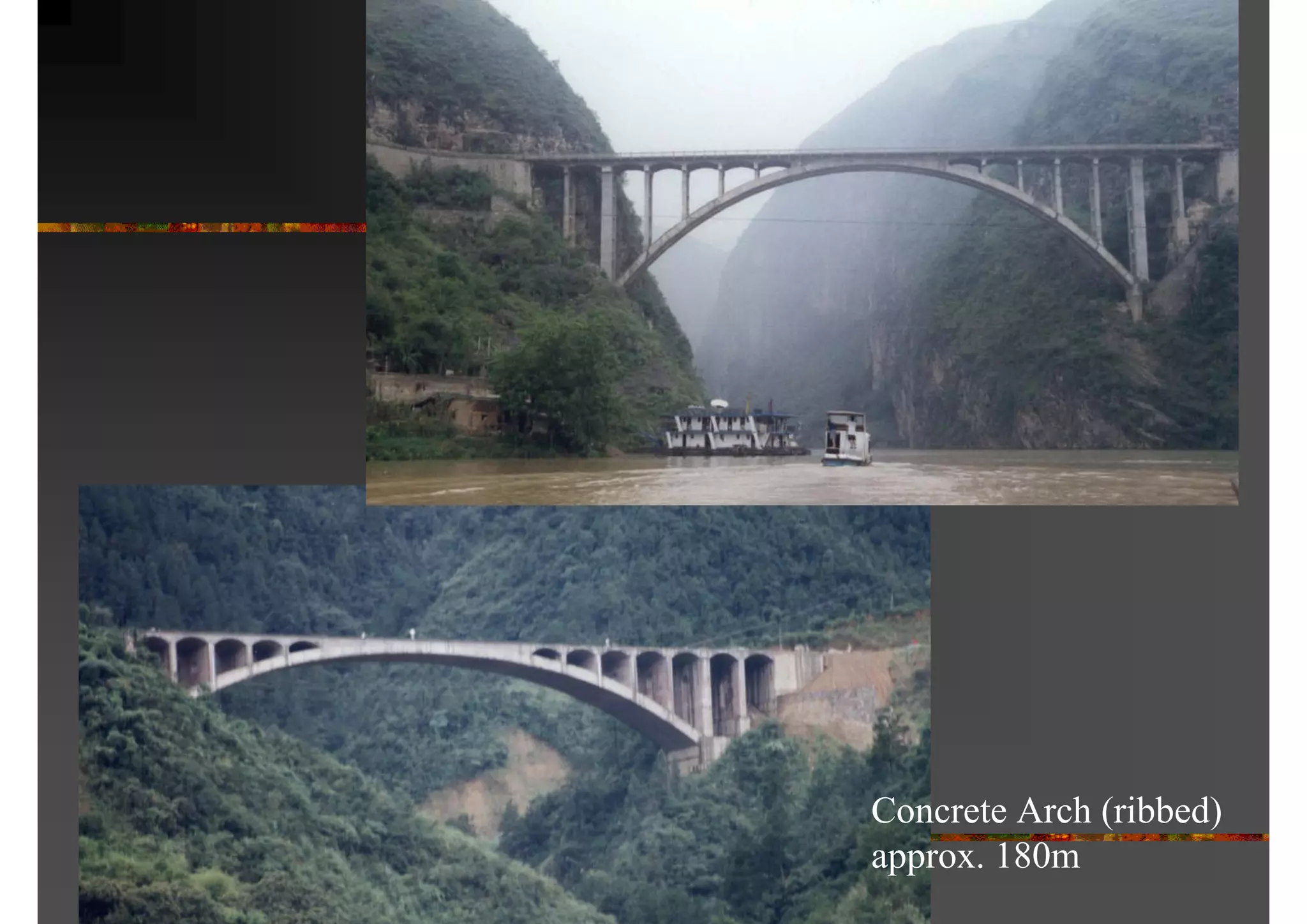


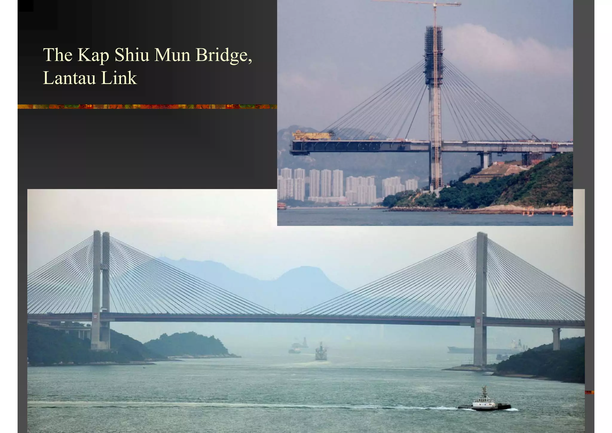
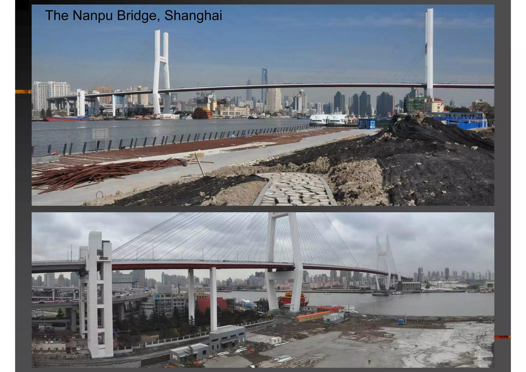

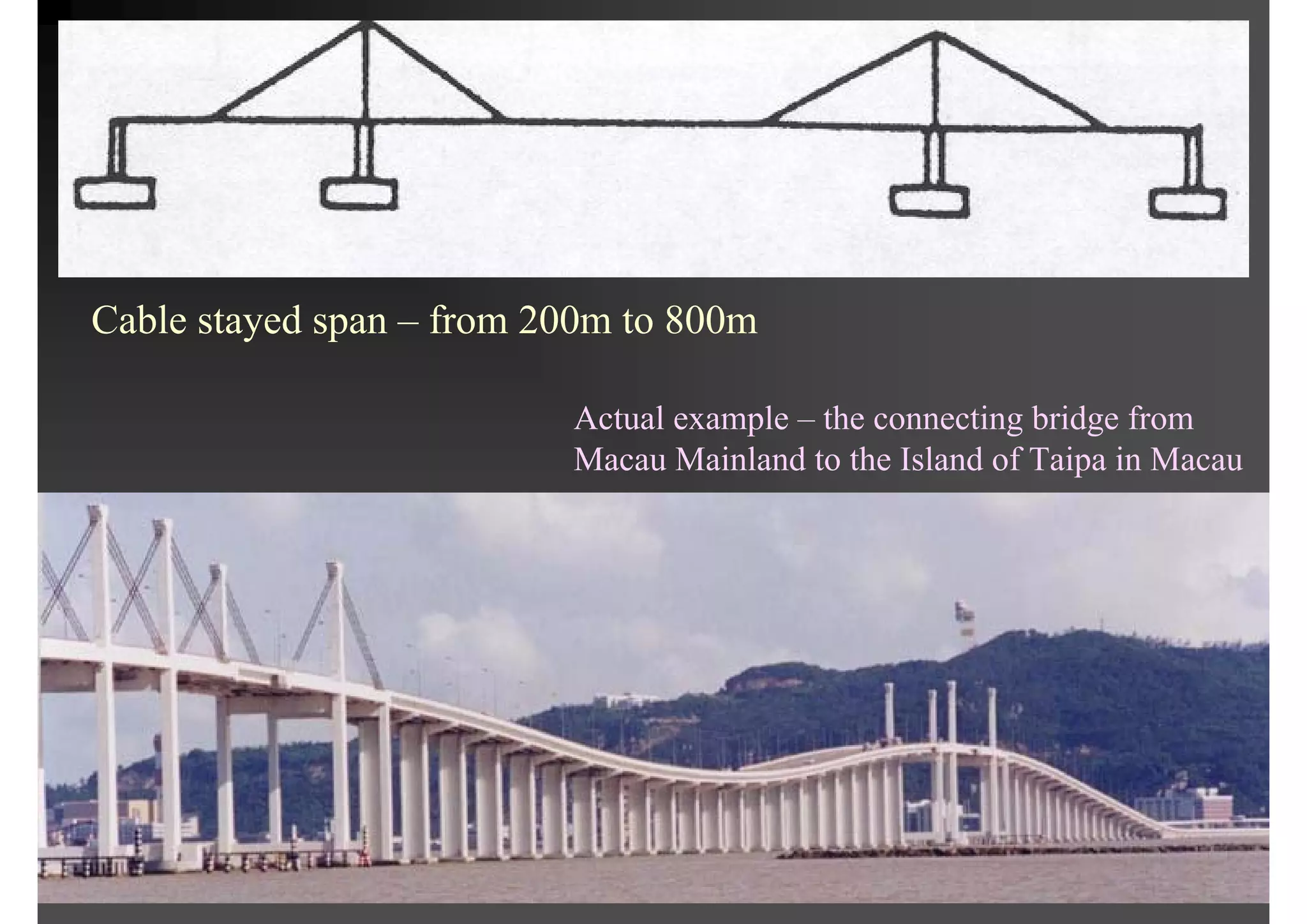
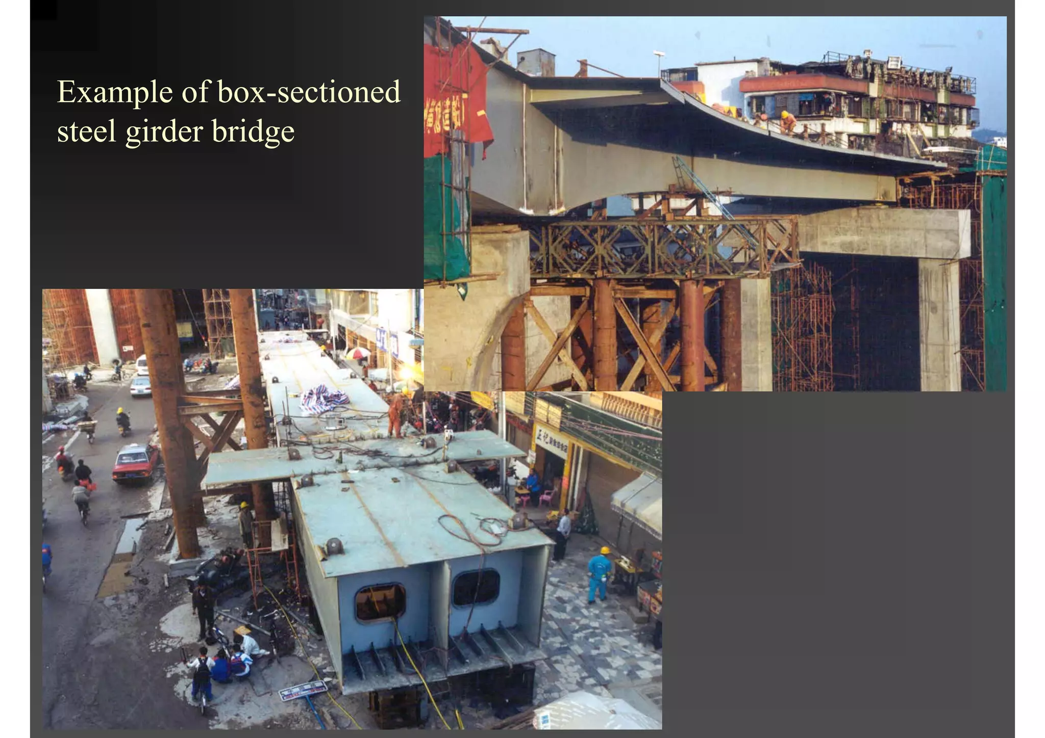


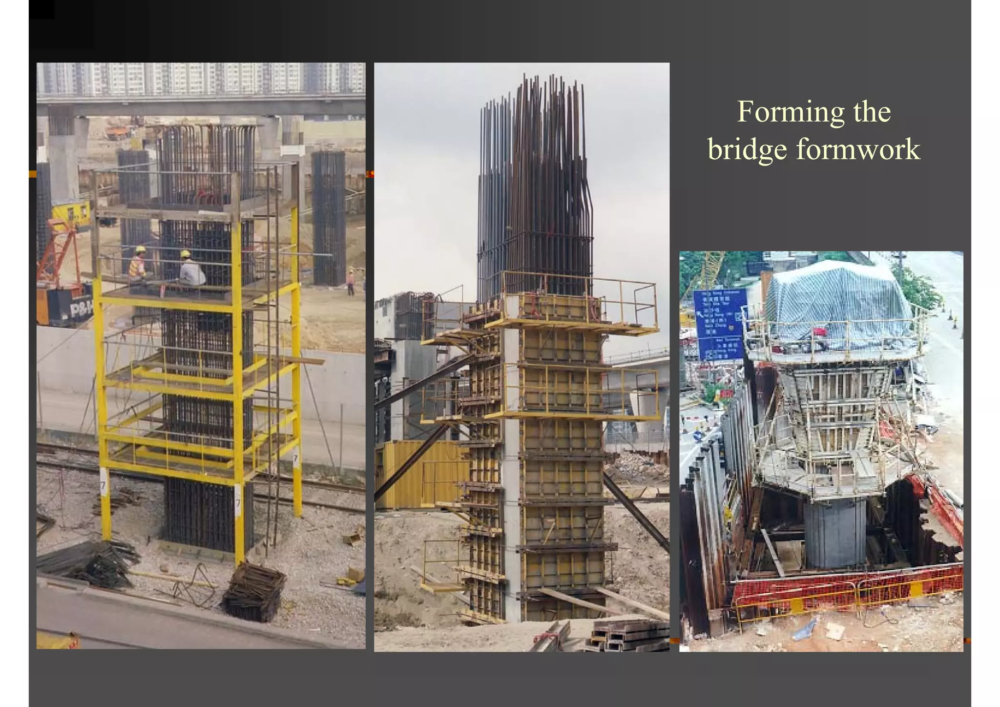
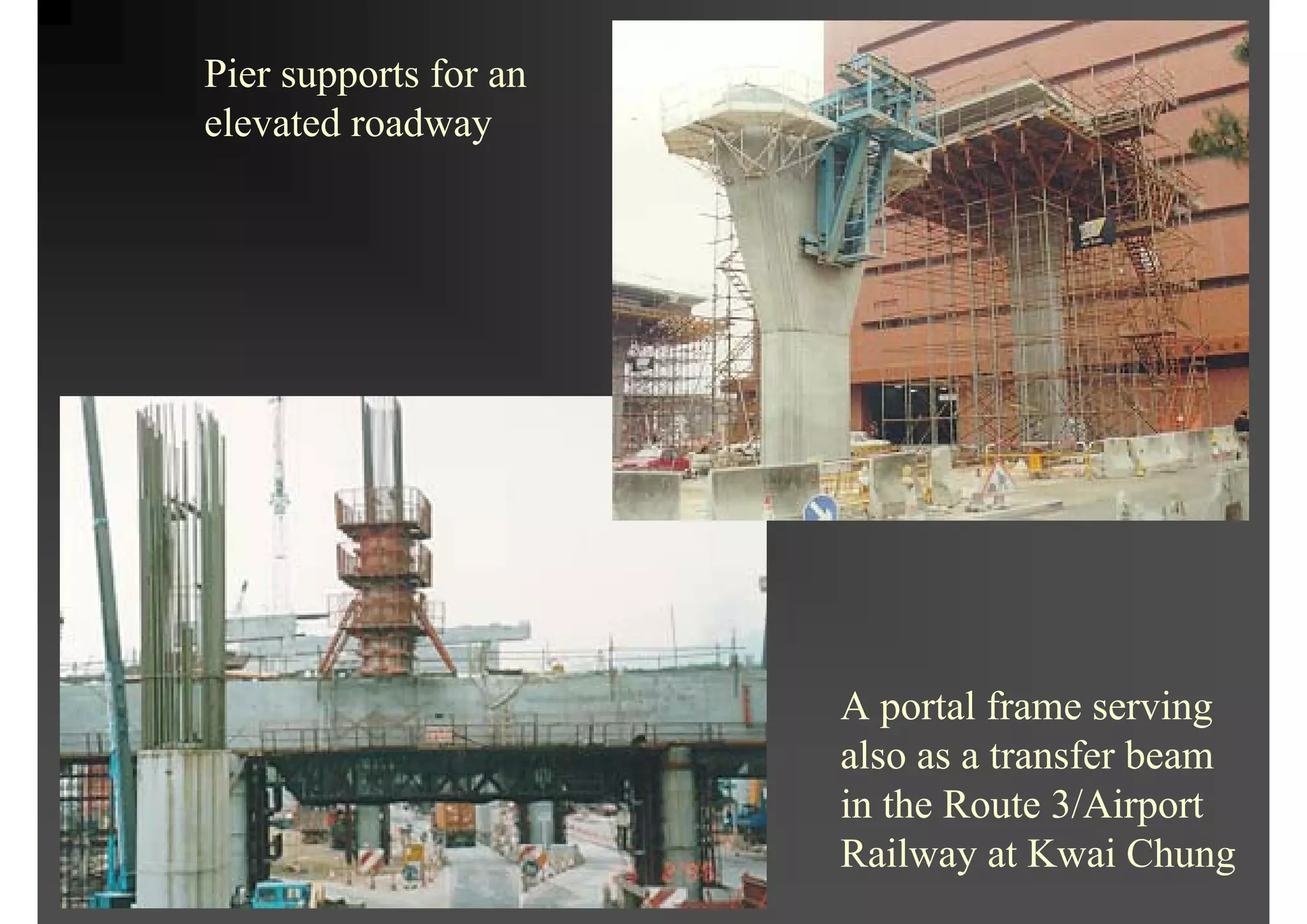


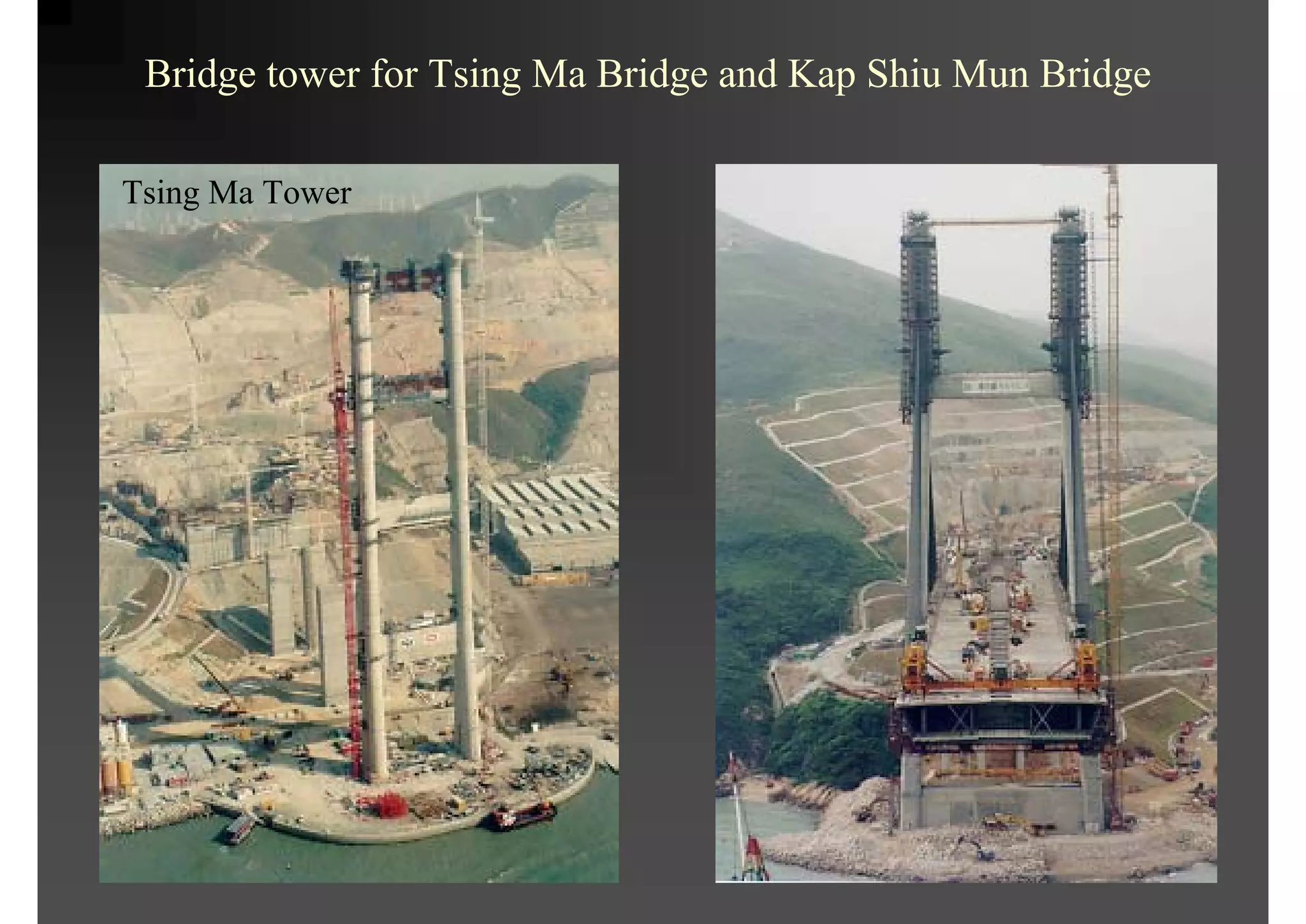


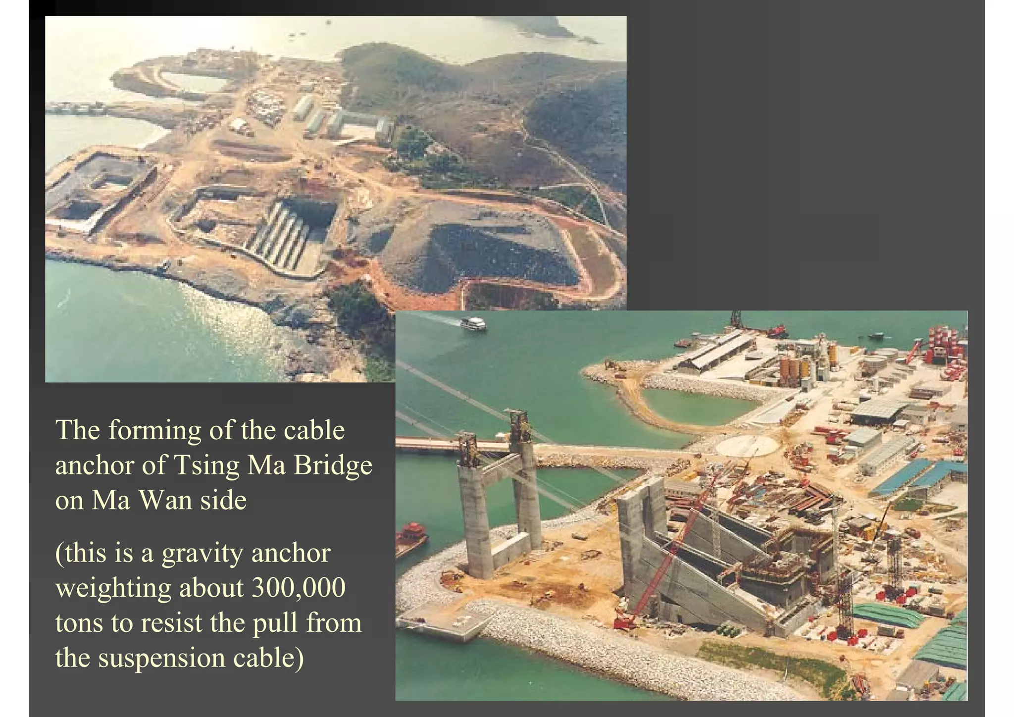

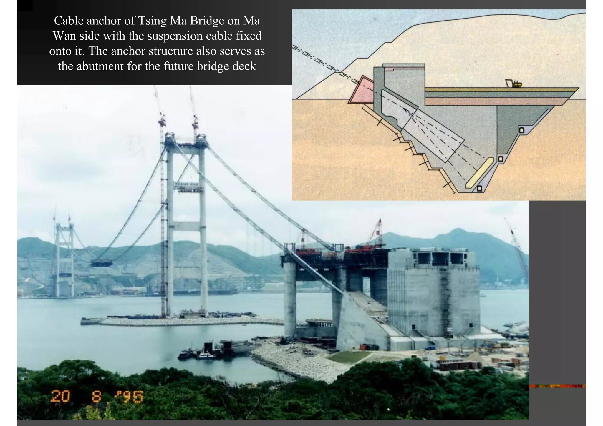
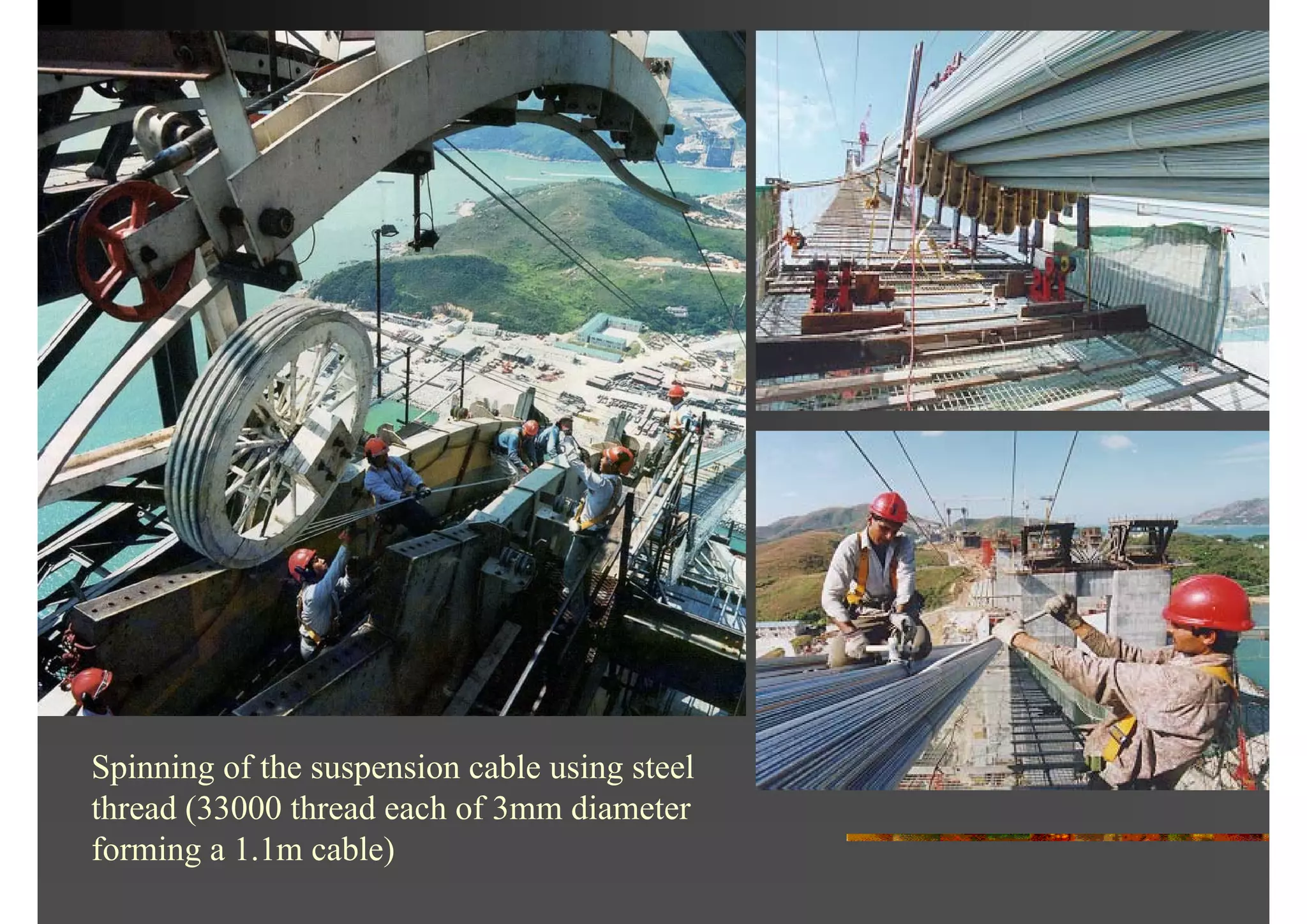


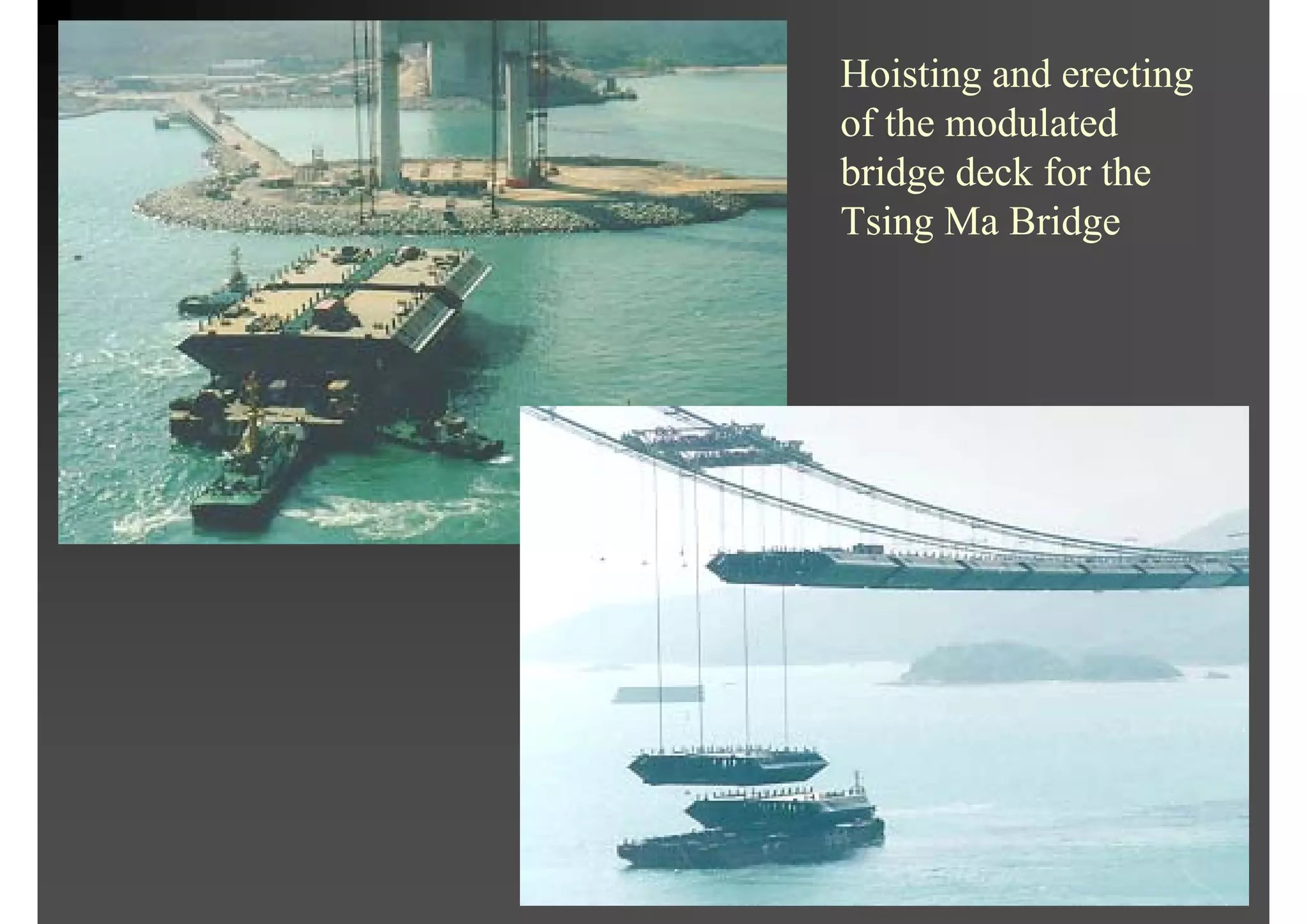
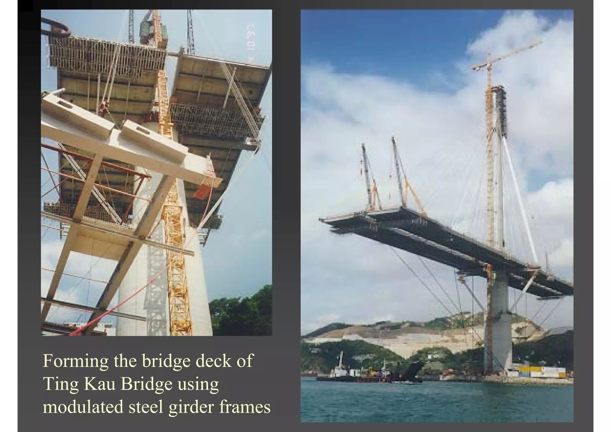


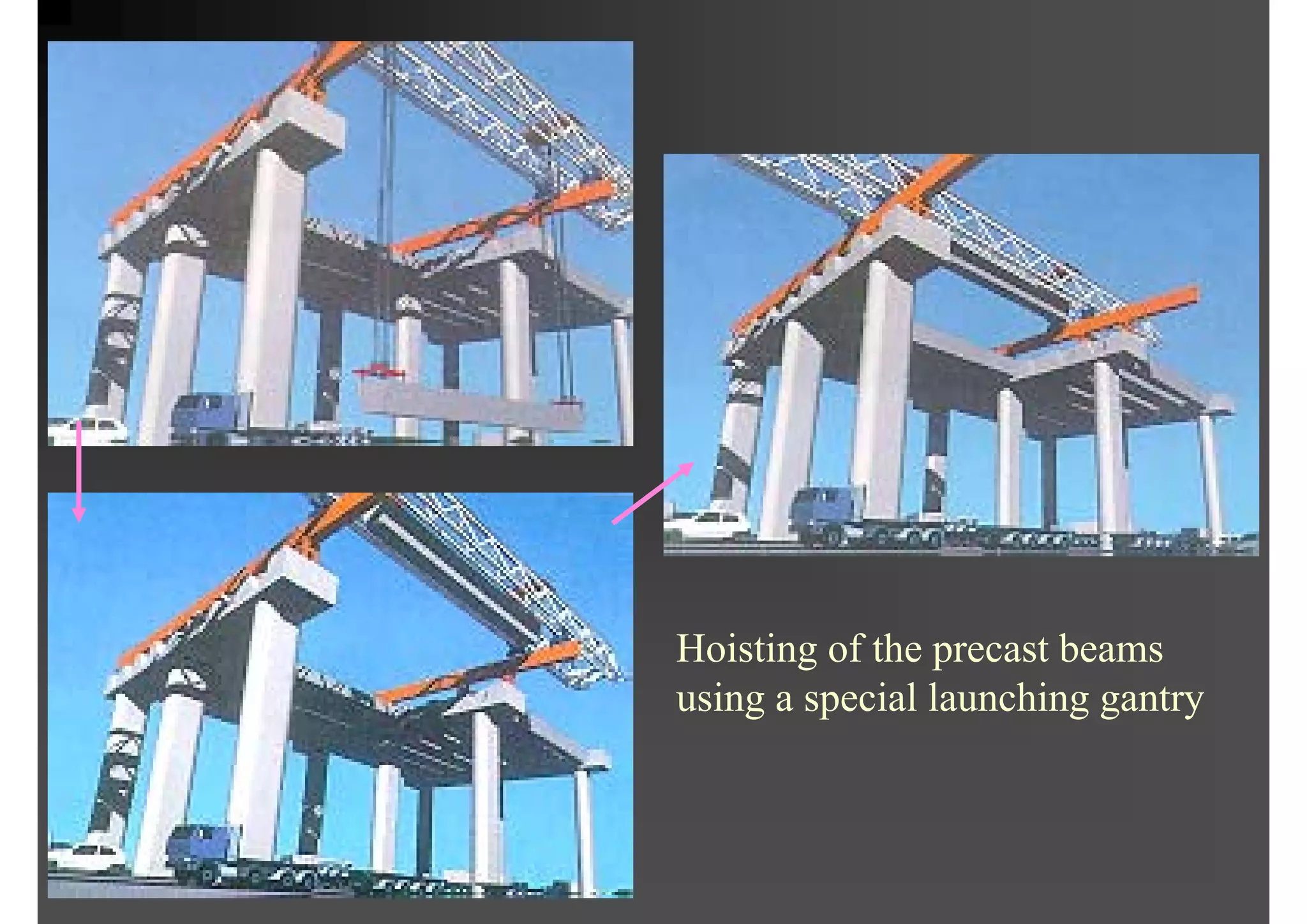
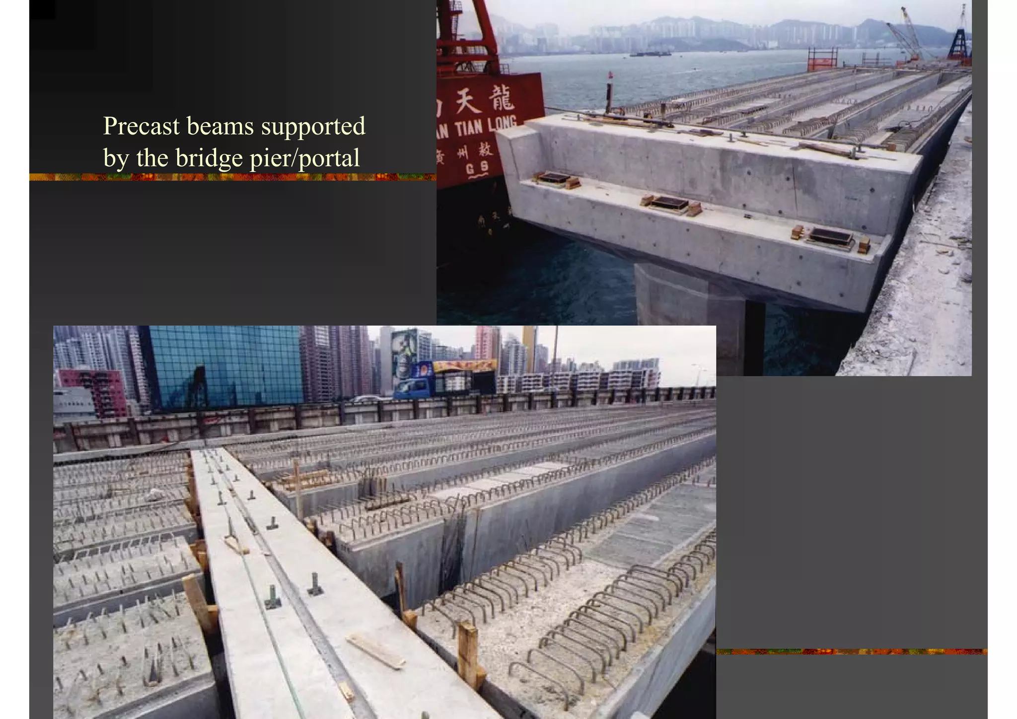

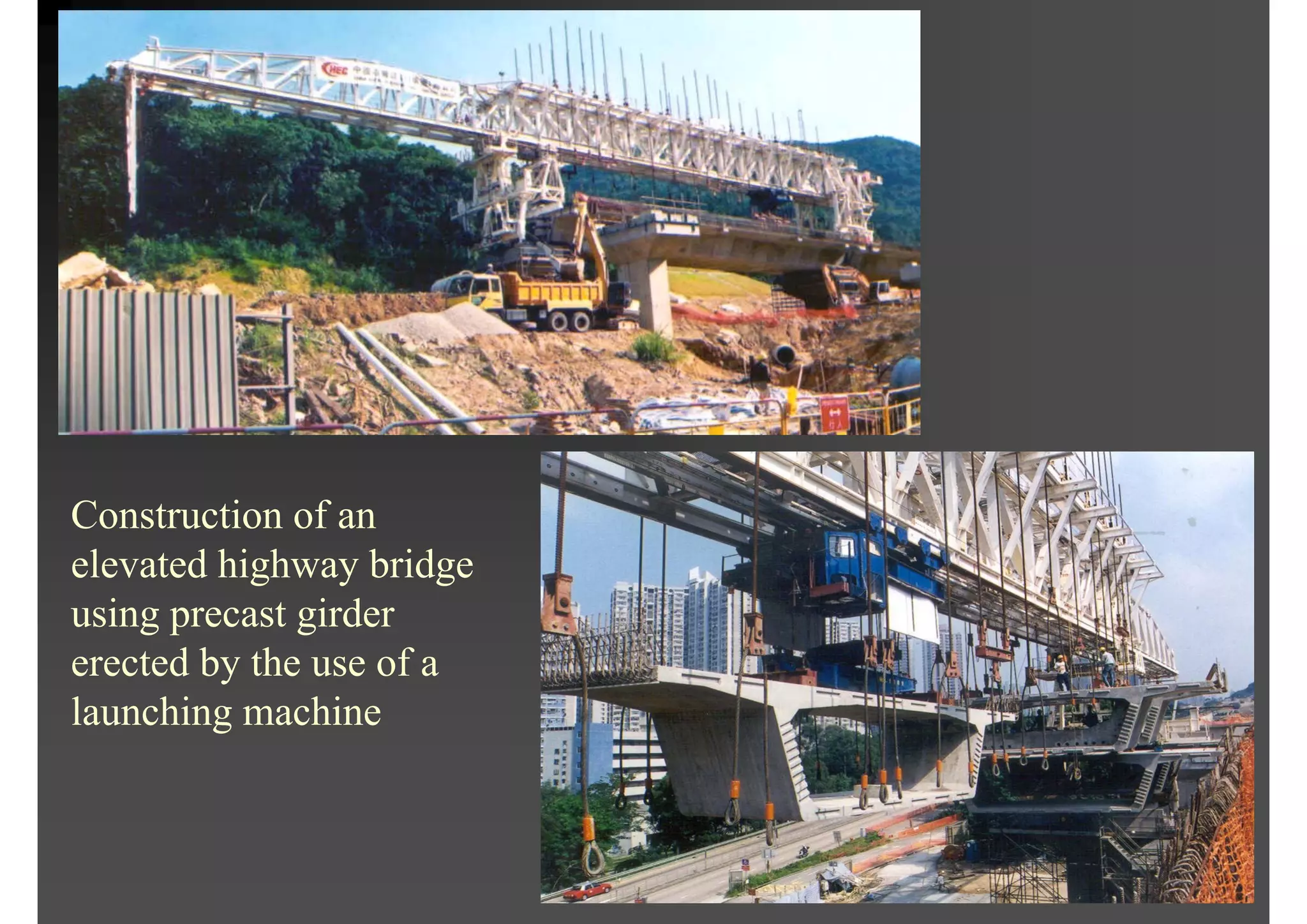
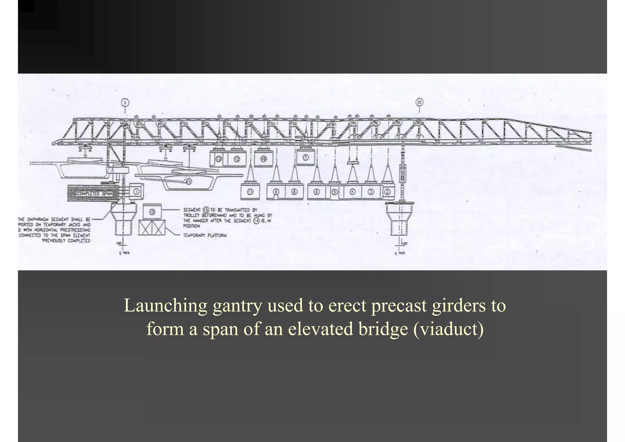

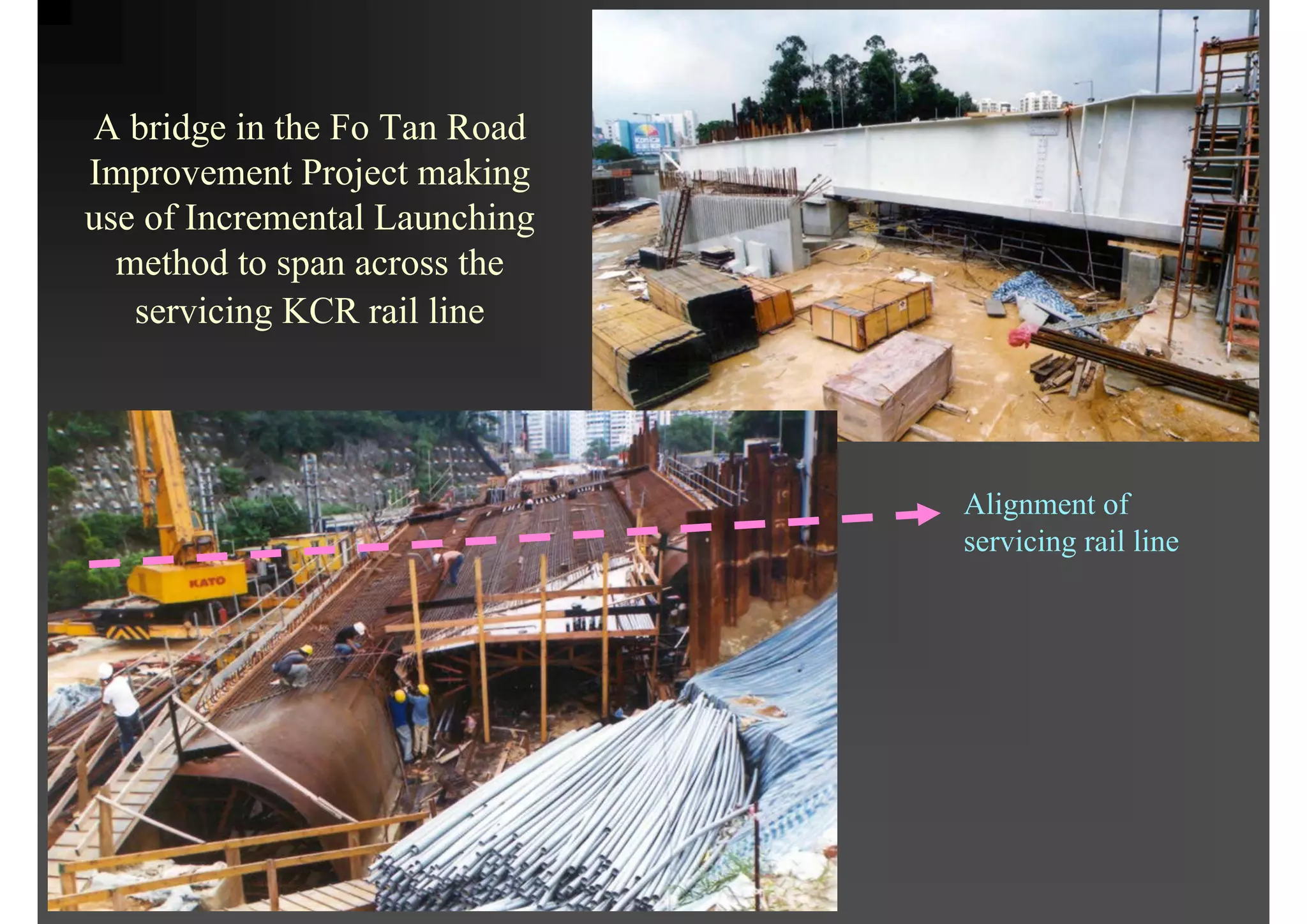


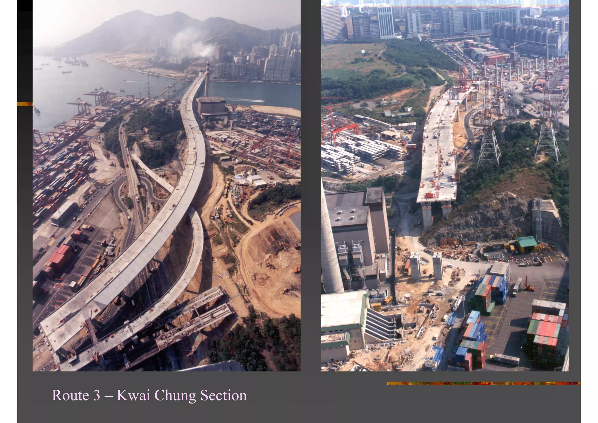


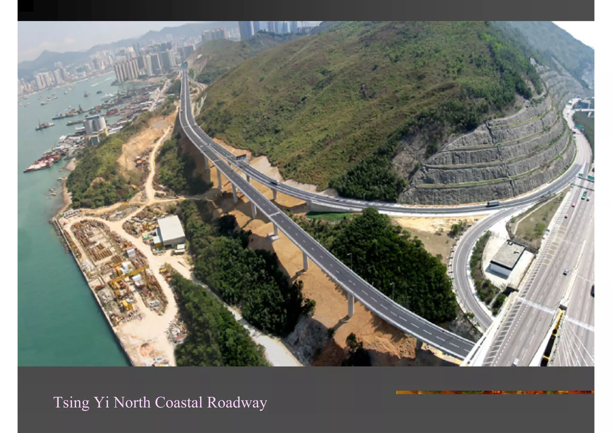


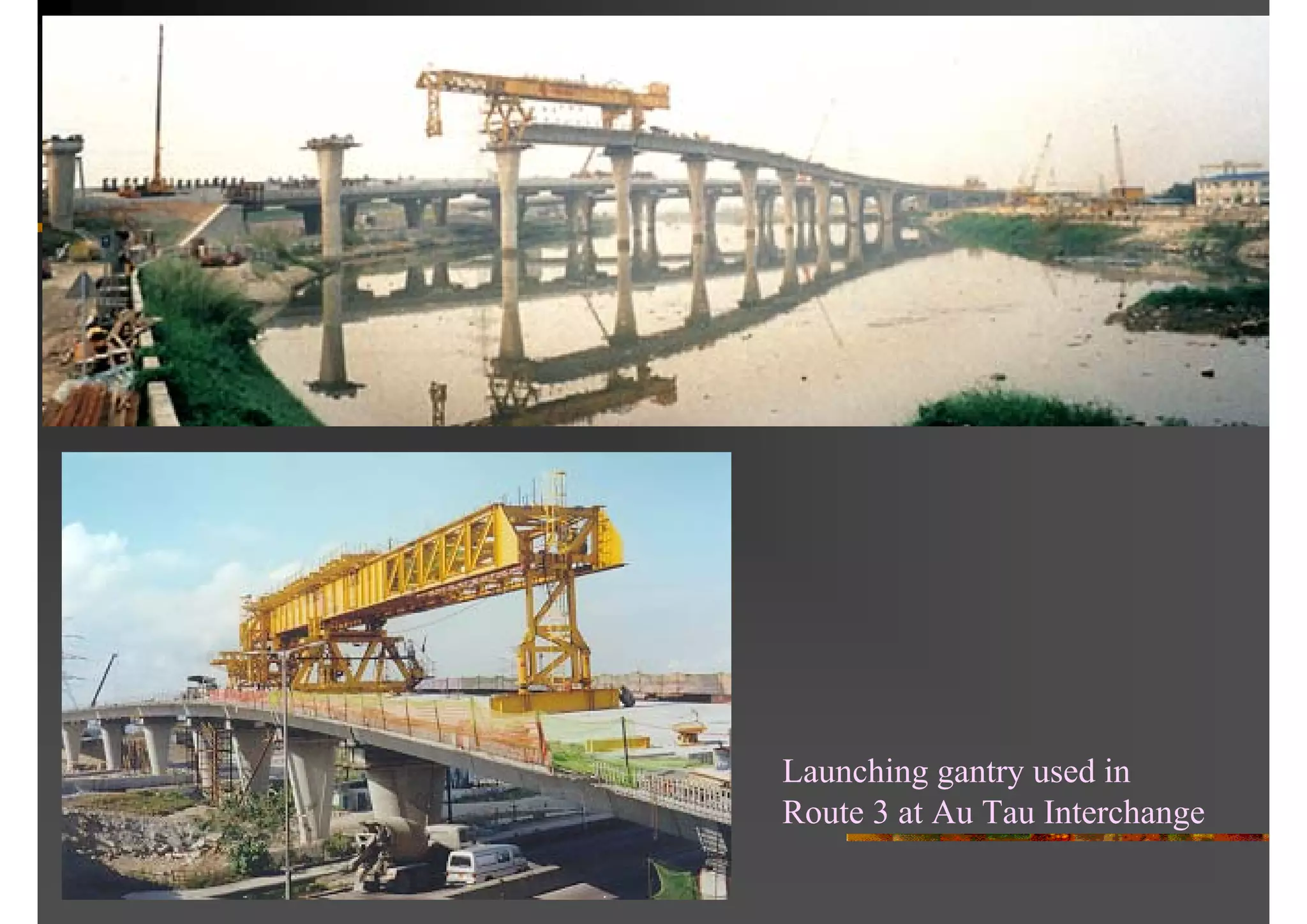
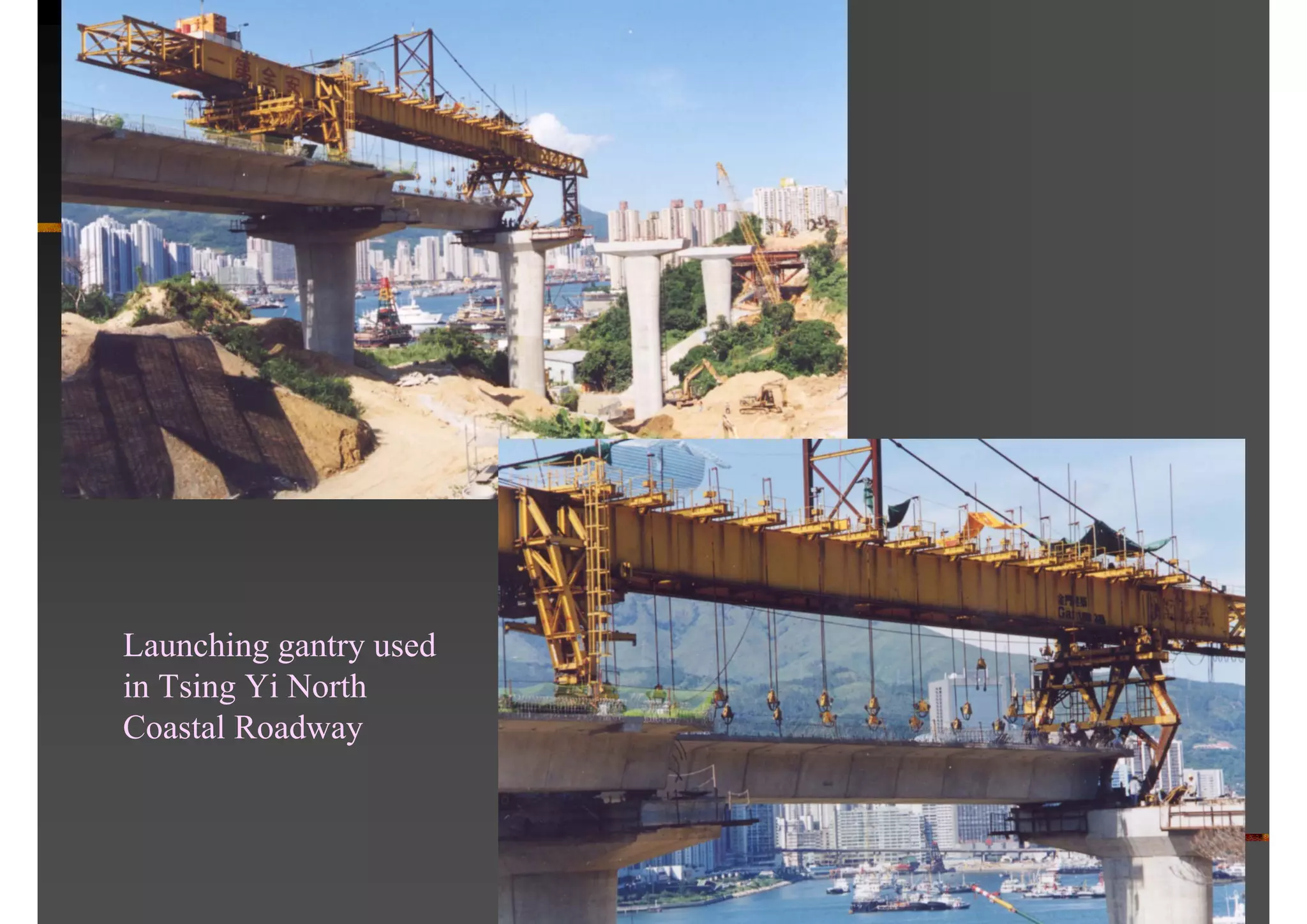

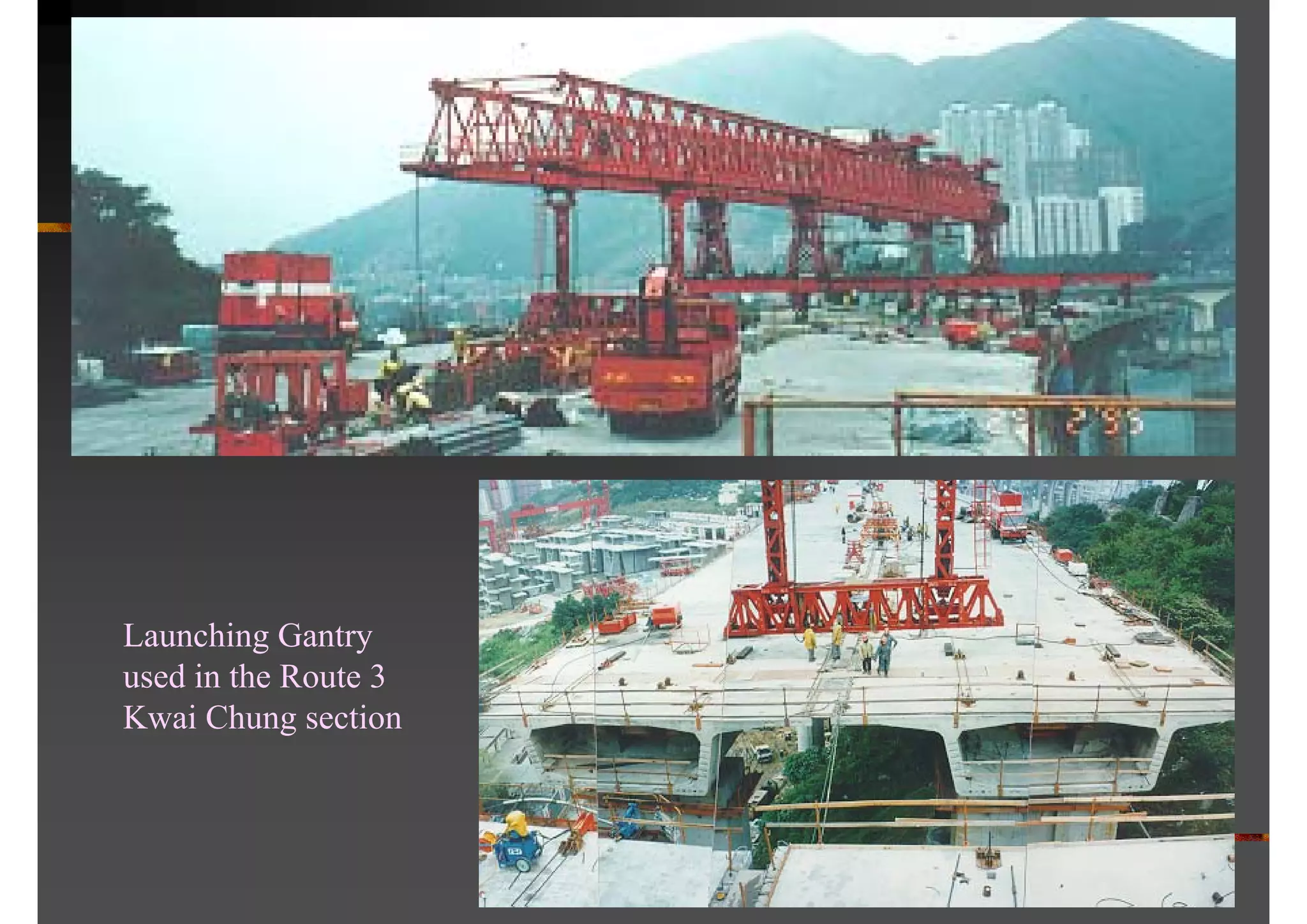


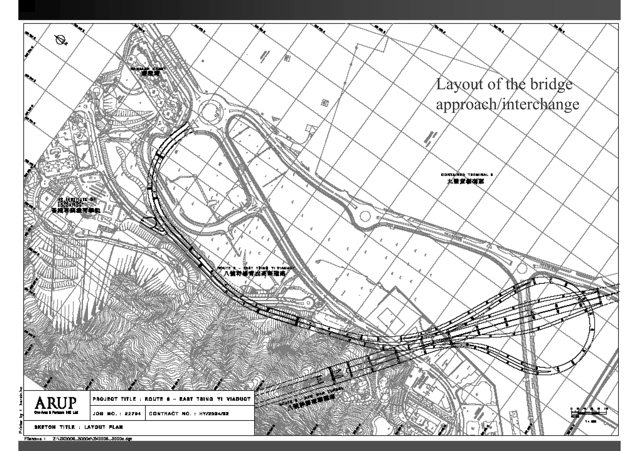


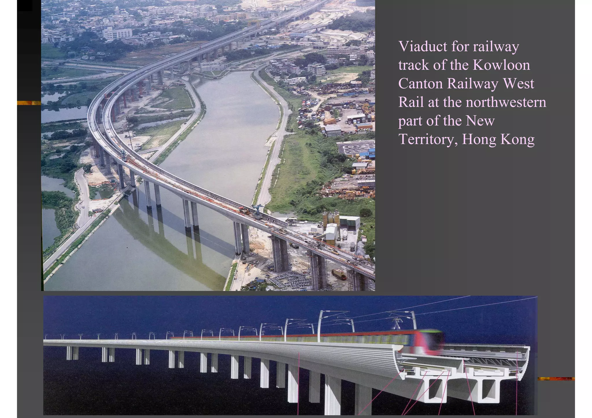

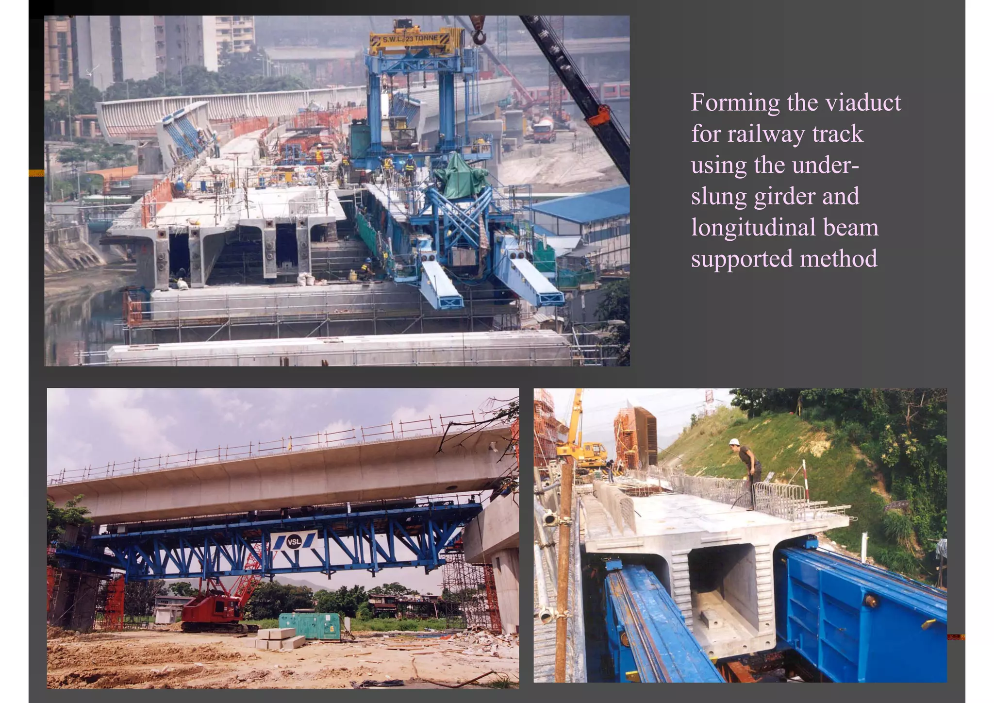
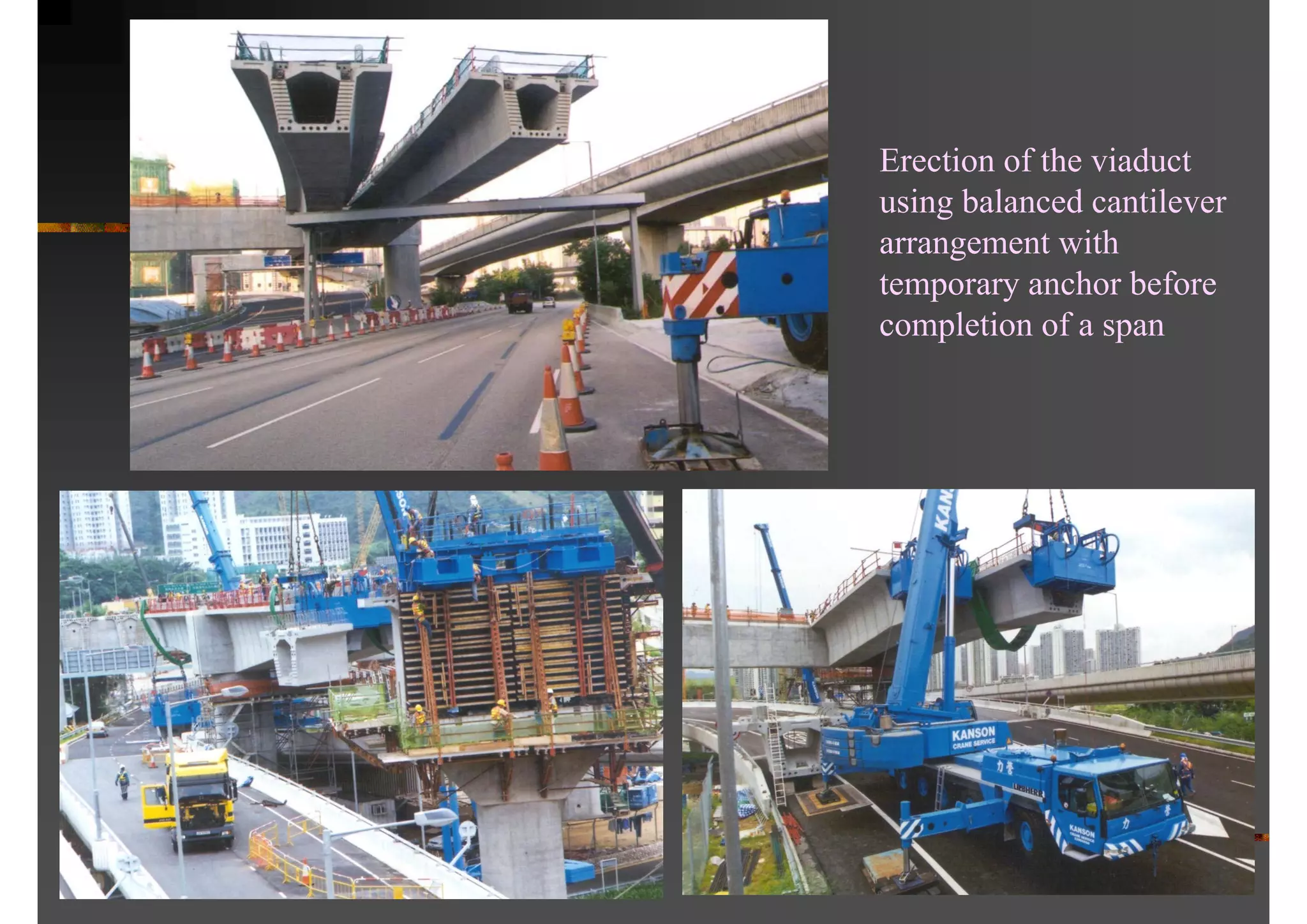
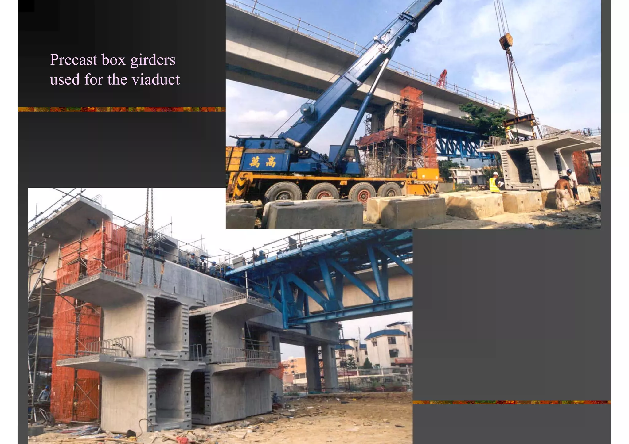


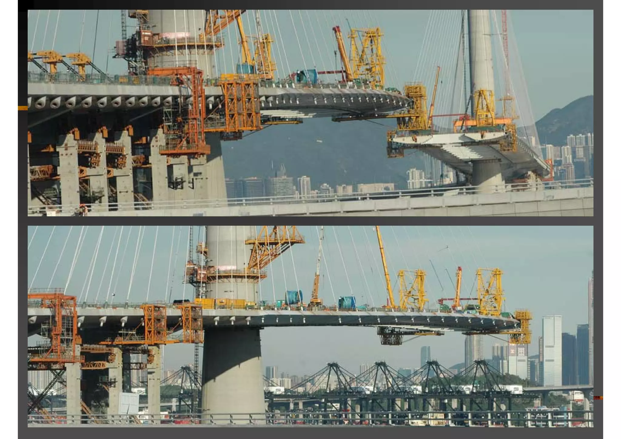


The document prepared by Raymond Wong elaborates on various materials and methods employed in the construction of long-span bridges, detailing types of materials like stone, steel, and reinforced concrete. It discusses common bridge forms, structural elements, and construction techniques, including foundations, piers, and different types of bridges such as cable-stayed and arch bridges with notable examples. Additionally, it covers innovative construction methods and specific projects, providing insights into the design and engineering considerations for bridge construction.


