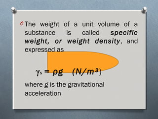
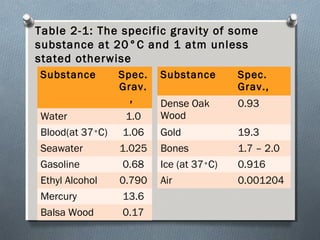
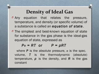
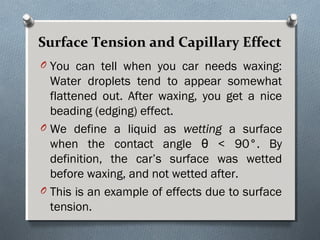
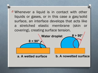
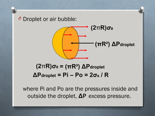
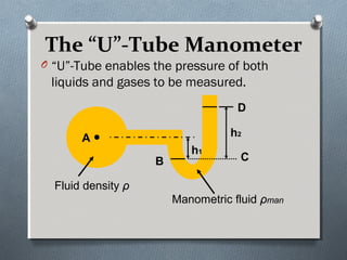
FLUIDFLUID
MECHANICSMECHANICS
ENGR. RICHARD T. BARNACHEA
CE Instructor
REFERENCES:
O Fluid Mechanics 8th
Edition
by: Fox, McDonald, Pritchard
O Essentials of Fluid Mechanics
by: John M. Cimbala
Yunus A. Cengel
O Mechanics of Fluids 4th
Edition
by: Potter, Wiggert, Ramadan
O Mechanics of Fluids 6th
Edition
by: Frank M. White
What is Fluid Mechanics?What is Fluid Mechanics?
O Fluid MechanicsFluid Mechanics is defined as the science
that deals with the behavior of fluids at rest
(fluid statics) or in motion (fluid dynamics).
O It deals with liquids and gases in motion or at
rest.
O MechanicsMechanics is the oldest physical science
that deals with both stationary and moving
bodies under the influence of forces.
O Fluid Mechanics itself is also divided into
several categories.
The study of the motion of fluids that
are practically incompressible (such as
liquids, especially water, and gases at
low speeds) referred to as
hydrodynamicshydrodynamics.
A subcategory of hydrodynamics is
hydraulicshydraulics, which deals with liquid
flows in pipes and open channels.
A subcategory of hydrodynamics is
hydraulicshydraulics, which deals with liquid
flows in pipes and open channels.
Gas dynamicsGas dynamics deals with the flow of
gases that undergo significant density
changes, such as flow of gases through
nozzles at high speeds.
The category of aerodynamicsaerodynamics deals
with the flow of gases (especially air)
over bodies such as aircraft, rockets,
and automobiles at high or low speeds.
What is aWhat is a FluidFluid??
a substance in the liquid or gas phase.
a substance that deforms continuously
under the application of the shear
stress no matter how small the shear
stress may be.
Difference in behavior of a solid and a
fluid due to a shear force.
F
F
a. Solid or Fluid b. Solid or Fluid
c. Fluid only
Classification of Fluid FlowsClassification of Fluid Flows
There is a wide variety of fluid flow problems
encountered in practice, and is usually
convenient to classify them on the basis of
some common characteristics to make it
feasible to study them in groups.
Internal versus External Flow
Compressible versus Incompressible Flow
Laminar versus Turbulent Flow
Steady versus Unsteady Flow
Internal versus External Flow
A fluid flow is classified as being internal
or external, depending on whether the fluid
flows is confined space or over a surface.
The flow of an unbounded fluid over a
surface such as a plate or a wire is
external flowexternal flow. Example airflow over a
ball.
The flow in a pipe or duct is internalinternal
flowflow if fluid is completely bounded by solid
surfaces. Example water flow in a pipe.
Compressible versus Incompressible
A flow is classified as being
compressible or incompressible,
depending on the level of variation of
density during flow.
Incompressibility is an approximation
in which a flow is said to be
incompressibleincompressible if the density
remains nearly constant throughout.
Laminar versus Turbulent Flow
Some flows are smooth and orderly while others
are rather chaotic.
The highly ordered fluid motion characterized by
smooth layers of fluid is called laminarlaminar.
The flow of high-viscosity fluids such as oil at
low velocities is typically laminar.
The highly disordered fluid motion that typically
occurs at high velocities and is characterized by
velocity fluctuations is called turbulentturbulent.
The flow of low viscosity fluids such as air at
high velocities is typically turbulent.
Steady versus Unsteady Flow
The terms steady and uniform are used
frequently in engineering, and it is
important to have a clear understanding of
their meanings.
The term steadysteady implies no change at a
point with time. The opposite of steady is
unsteady.
The term uniformuniform implies no change with
location over a specified region.
Methods of AnalysisMethods of Analysis
The first step in solving a problem is to
define the system that you are
attempting to analyze.
In basic mechanics, we made
extensive use of the free-body
diagram.
We will use a system or a control
volume, depending on the problem
being studied.
O A SYSTEMSYSTEM is defined as a fixed, identifiable
quantity of mass; the system boundaries separate
the system from the surroundings.
O Systems may be considered to be closed or open,
depending on whether a fixed mass or a volume in
space is chosen for study.
SYSTEMSYSTEM
Surroundings
Boundary
O The mass or region outside the
system is called the
SURROUNDINGSSURROUNDINGS.
O The real or imaginary surface that
separates the system from its
surroundings is called the
BOUNDARYBOUNDARY.
O The boundary of a system can be
fixed or movable.
The gas in the cylinder is the system. If the gas is
heated, the piston will lift the weight; the boundary of
the system thus moves. Heat and work may cross the
boundaries of the system, but the quantity of matter
within the system boundaries remains fixed. No mass
crosses the system boundaries.
Gas
2 kg
1m³
Gas
2 kg
1m³
Moving Boundary
Fixed Boundary
Weight
Weight
O Control volumeControl volume is an arbitrary volume in
space through which fluid flows.
O The geometric boundary of the control
volume is called the control surfacecontrol surface.
O The control surface may be real or
imaginary; it may be at rest or in motion.
Contro
l
Volum
e
Control
Surface
(real
boundary)
Imaginary
boundary
Importance of Dimensions andImportance of Dimensions and
UnitsUnits
O Any physical quantities can be characterized
by dimensions.
O The magnitudes assigned to the dimensions
are called unitsunits.
O Some basic dimensions such as mass m,
length L, time t, and temperature T are
selected as primary or fundamentalprimary or fundamental
dimensionsdimensions.
Six Fundamental Quantities:Six Fundamental Quantities:
O Meter (m) for length
O Kilogram(kg) for mass
O Second (s) for time
O Ampere (A) for electric current
O Degree Kelvin (°K) for temperature
O Candela (cd) for luminous intensity
(amount of light)
Chapter Two
PROPERTIES OF FLUIDS
O In this chapter, we discuss properties that are
encountered in the analysis of fluid flow.
O First we discuss intensive and extensive properties
and define density and specific gravity.
O This is followed by a discussion of the properties of
vapor pressure, energy and its various forms, and
the specific heat of ideal gases and incompressible
substances.
O Then we discuss the property viscosity, which plays
the dominant role in most aspects of fluid flow.
O Finally, we present the property surface tension and
determine the capillary rise from static equilibrium
conditions.
O Any characteristic of a system is called propertyproperty.
Some familiar properties are pressure,
temperature, volume, and mass.
O Properties are considered to be either intensive
or extensive.
O Intensive propertiesIntensive properties are those that are
independent of the mass of the system, such as
temperature and pressure.
O Extensive propertiesExtensive properties are those whose values
depend on the size or extent of the system.
Total mass, total volume, and total momentum
are some examples of extensive properties.
DensityDensity
Ois defined as mass per unit
volume.
density, ρ = m/V (kg/m³)
The reciprocal of density is the
specific volume, υ.
υ = V/m = 1/ρ
O is defined as the ratio of the density of a
substance to the density of some
standard substance at a specified
temperature (usually water at 4°C, for
which ρ = 1000 kg/m³).
O Specific Gravity: SG = ρfluid/ρwater
O The specific gravity of a substance is a
dimensionless quantity.
Specific Gravity or RelativeSpecific Gravity or Relative
DensityDensity
O The weight of a unit volume of a
substance is called specific
weight, or weight density, and
expressed as
γs = ρg (N/m³)
where gg is the gravitational
acceleration
Table 2-1: The specific gravity of some
substance at 20°C and 1 atm unless
stated otherwise
Substance Spec.
Grav.
,
Water 1.0
Blood(at 37°C) 1.06
Seawater 1.025
Gasoline 0.68
Ethyl Alcohol 0.790
Mercury 13.6
Balsa Wood 0.17
Substance Spec.
Grav.,
Dense Oak
Wood
0.93
Gold 19.3
Bones 1.7 – 2.0
Ice (at 37°C) 0.916
Air 0.001204
Density of Ideal GasDensity of Ideal Gas
O Any equation that relates the pressure,
temperature, and density (or specific volume) of
a substance is called an equation of stateequation of state.
O The simplest and best-known equation of state
for substance in the gas phase is the ideal-gas
equation of state, expressed as
Pυ = RT or P = ρRT
where P is the absolute pressure, υ is the spec.
volume, T is the thermodynamic (absolute)
temperature, ρ is the density, and R is the gas
constant
The gas constant R is different for each
gas and is determined from
R = RR = Ruu /M/M
where Ru is the universal gas
constant, and M is the molar mass
( also called molecular weight) of the
gas.
Ru = 8.314 kJ/kmol*K (SI System)
Ru = 1.986 Btu/lbmol*R (English System)
The thermodynamic temperature scale in the
SI is the Kelvin scale, and the temperature
unit on this scale is the kelvin, designated by
K.
In the English system, it is Rankine scale, and
the temperature unit on this scale is rankine,
R.
Various temperature scales are related to
each other by
T(K) = T(°C) + 273.15 = T(R)/1.8T(K) = T(°C) + 273.15 = T(R)/1.8
T(R) = T(°F) + 459.67 = 1.8 T(K)T(R) = T(°F) + 459.67 = 1.8 T(K)
Example:Example:
Determine the density, specific
gravity, and mass of the air in a room
whose dimensions are 4m x 5m x 6m
at 100 kPa and 25°C.
AIR
P = 100kPa
T = 25°C
Solution:Solution:
O Gas constant of air is
R = 0.287 kPa*m³/kg*K
O Density :
ρ = P/RT
ρ = 100kPa/(0.287 kPa*m³/kg*K)(25+273.15)K
ρ = 1.17 kg/m³
O Specific Gravity:
SG = ρ / ρH2O
SG = 1.17 kg/m³ / 1000 kg/m³
SG = 0.00117
Mass of air
V = (4m x 5m x 6m) = 120m³
m = ρV
m = (1.17 kg/m³)(120m³)
m = 140 kg
Vapor PressureVapor Pressure
At a given pressure, the temperature at which
a pure substance changes phase is called the
saturation temperature, Tsaturation temperature, Tsatsat.
Likewise, at a given temperature, the
pressure at which a pure substance changes
phase is called the saturation pressure,saturation pressure,
PPsatsat.
For example:
At an absolute pressure of 1 standard
atmosphere (1 atm or 101.325 kPa), the
saturation of water is 100°C.
The vapor pressure (Pv)vapor pressure (Pv) of a pure substance
is defined as the pressure exerted by its vapor in
phase equilibrium with its liquid at a given
temperature.
Vapor pressure is a property of the pure
substance, and turns out to be identical to the
saturation pressure of the liquid (Pv = PsatPv = Psat).
We must be careful not to confuse vapor
pressure with partial pressure.
Partial pressurePartial pressure is defined as the pressure of
a gas or vapor in a mixture with other gases.
Energy and Specific HeatEnergy and Specific Heat
O Energy can exist in numerous forms such as
thermal, mechanical, kinetic, potential,
electrical, magnetic, chemical, and nuclear, and
their sum constitute the total energy Etotal energy E of a
system.
O The forms of energy related to the molecular
structure of a system and the degree of the
molecular activity are referred to as the
microscopic energymicroscopic energy.
O The sum of all microscopic forms of energy is
called the internal energyinternal energy of a system and is
denoted by UU.
The macroscopic energy of a system is
related to motion and the influence of
some external effects such as gravity,
magnetism, electricity, and surface
tension.
The energy that a system possesses as a
result of its motion relative to some
reference frame is called kinetic energykinetic energy.
The energy that a system possesses as a
result of its elevation in a gravitational field
is called potential energypotential energy.
O The international unit of energy is the joulejoule
or kilojouleor kilojoule.
1 kJ = 1000 J
1 J = 1 N*m
1 Btu (British thermal unit) = 1.0551 kJ
1 cal (calorie) = 4.1868 J
ViscosityViscosity
O There is property that represents the internal
resistance of a fluid to motion or the fluidity,
and the property is the viscosityviscosity.
O The force a flowing fluid exerts on a body in
the flow direction is called the drag forcedrag force,
and the magnitude of this force depends on
viscosity.
O To obtain a relation for viscosity, consider a
fluid layer between two very large parallel plates
( or equivalently, two parallel plates immersed
in a large body of fluid) separated by a distance
ℓ.
O Now a constant parallel force F is applied to the
upper plate while the lower plate is held fixed.
F
ℓ
V
u=0
u=V
dβ
y
x
Area A
After the initial transients, it is observed that
the upper plate moves continuously under
the influence of this force at a constant
velocity VV.
The fluid in contact with the upper plate
sticks to the plate surface and moves with it
at the same velocity, and the shear stress
(tau)Ʈ(tau)Ʈ acting on this layer is
= F/AƮ = F/AƮ
where A is the contact area between
plate and the fluid.
O The rate of deformation of a fluid element is
equivalent to the velocity gradient du/dydu/dy.
O It can be verified experimentally that for most
fluids the rate of deformation is directly
proportional to the shear stress ƮƮ,
Ʈ α dβ/dy or Ʈ α du/dy
Fluids for which the rate of deformation is
proportional to the shear stress are called
Newtonian fluidsNewtonian fluids after Sir Isaac Newton,
who expressed it first in 1687.
O Most common fluids such as water, air,
gasoline, and oils are Newtonian fluids.
Blood is an example of non-Newtonian fluid.
O In one-dimensional shear flow of Newton
fluids, shear stress can be expressed by the
linear relationship
Ʈ = μdu/dy (N/m²)
where the constant of proportionality μ is
called coefficient of viscosity or dynamic (or
absolute) viscosity of the fluid whose unit is
kg/m*s or N*s/m².
O The shear force acting on a Newtonian
fluid layer ( or by Newton’s third law, the
force acting on the plate) is
F = A =Ʈ μAdu/dy (N)
Then the force F required to move the
upper plate at a constant velocity V while
the lower plate remains stationary is
F = μAV/ℓ
O In fluid mechanics the ratio of absolute
viscosity to density often arises.
O This ratio is given the name kinematickinematic
viscosityviscosity and is represented by the symbol
υ.
υυ == μμ // ρρ (m²/s)
Surface Tension and Capillary EffectSurface Tension and Capillary Effect
O You can tell when you car needs waxing:
Water droplets tend to appear somewhat
flattened out. After waxing, you get a nice
beading (edging) effect.
O We define a liquid as wetting a surface
when the contact angle θ < 90°. By
definition, the car’s surface was wetted
before waxing, and not wetted after.
O This is an example of effects due to surface
tension.
O Whenever a liquid is in contact with other
liquids or gases, or in this case a gas/solid
surface, an interface develops that acts like
a stretched elastic membrane (skin or
covering), creating surface tension.
θ < 90°
θ > 90°Water droplet
a. A wetted surface b. A nowetted surface
O The pulling force that causes this
tension acts parallel to the surface
and is due to the attractive forces
between the molecules of the liquid.
O The magnitude of this force per unit
length is called surface tensionsurface tension
( or coefficient of surface( or coefficient of surface
tension)tension) σσss and is expressed in the
unit N/m (lbf/ft).
O Droplet or air bubble:
where Pi and Po are the pressures inside and
outside the droplet, ΔP excess pressure.
(2πR)σσss
(πR²) ΔPdroplet
(2πR)σσss = (πR²) ΔPdroplet
ΔPdroplet = Pi – Po = 2σσss / R/ R
Capillary EffectCapillary Effect
O Another interesting consequence of
surface tension is the capillary effectcapillary effect,
which is the rise and fall of a liquid in a
small-diameter tube inserted into the
liquid.
O Such narrow tubes or confined flow
channels are called capillariescapillaries.
O The curved free surface of a liquid in a
capillary tube is called the meniscusmeniscus.
O Capillary rise:
(2πR)σσss
W
h
2R
liquid
Φ
h = 2σσss coscosΦ
ρgR
Example #1:
O A 0.6mm diameter glass tube is
inserted into water at 20°C in a cup.
Determine the capillary rise of water in
the tube.
Example #2:
O A 1.9-mm-diameter tube is inserted
into an unknown liquid whose density
is 960 kg/m³, and it is observed that
the liquid rises 5 mm in the tube,
making a contact angle of 15°.
Determine the surface tension of the
liquid.
O In a diesel engine, the piston compress air
at 305 K to a volume that is one-sixteenth
of the original volume and a pressure that
is 48.5 times the original pressure. What is
the temperature of the air after the
compression?
Example #3:
O The pressure in an automobile tire depends
on the temperature of the air in the tire.
When the air temperature is 25°C, the
pressure gage reads 210 kPa. If the volume
of the tire is 0.025 m³, determine the
pressure rise in the tire when the air
temperature in the tire rises to 50°C. Also,
determine the amount of air that must be
bled off to restore pressure to its original
value at this temperature. Assume the
atmospheric pressure to be 100 kPa.
Example #4:
Example #5:
O The velocity distribution for laminar flow
between parallel plates is given by
u/umax = 1 – (2y/h)²
where h is the distance separating the plates
and the origin is placed midway between
the plates. Consider a flow of water at 20°C
with maximum speed of 0.05 m/s and
h=0.1mm. Calculate the force on a 1m²
section of the section of the lower plate and
give its direction.
Example #6:
O A 50-cm X 30-cm X 20-cm block weighing 150 N is
to be moved at a constant velocity of 0.8 mls on an
inclined surface with a friction coefficient of 0.27.
(a) Determine the force F that needs to be applied
in the horizontal direction. (b) If a O.4-mm-thick oil
film with a dynamic viscosity of 0.012 Pa . s is
applied between the block and inclined surface,
determine the percent reduction in the required
force.
PRESSURE ANDPRESSURE AND
FLUID STATICSFLUID STATICS
Objectives:
At the end of this chapter, the
students must be able to:
1.Determine precisely the variation of
pressure in a fluid at rest;
2.Calculate the forces exerted by a fluid at
rest on plane or curved submerged surfaces;
and
3.Analyze the stability of floating and
submerged bodies.
O This chapter deals with forces applied by fluids
at rest.
O The fluid property responsible for those forces
is pressure, which is a normal force exerted by
a fluid per unit area.
O We start this chapter with a detailed discussion
of pressure, including absolute and gauge
pressures, the pressure at a point, the
variation of pressure with depth in a
gravitational field, the manometer, the
barometer, and other pressure measurement
devices.
O This is followed by a discussion of the
hydrostatic forces applied on
submerged bodies with plane or curved
surfaces.
O We then consider the buoyant force
applied by fluids on submerged or
floating bodies, and discuss the
stability of such bodies.
PRESSUREPRESSURE
O PressurePressure is defined as a normal force
exerted by a fluid per unit area. We speak
of pressure only when we deal with gas or
a liquid.
O The counterpart of pressure in solids is
normal stress. Since pressure is defined as
force per unit area, it has the unit of
newton per square meter (N/m²), which is
called a Pascal (Pa). That is
1 Pa = 1 N/m²
O Three other pressure units commonly used
in practice, especially in Europe, standard
atmosphere, and kilogram-force per square
centimeter:
1 bar = 10 = 0.1 MPa = 100 kPa
1 atm = 101.325 kPa = 1.01325 bars
1 kgf/cm² = 9.807 N/cm² = 9.807x10 Pa
1 kgf/cm² = 0.9807 bar
1 kgf/cm² = 0.9679 atm
5
4
O The actual pressure at a given position is
called absolute pressureabsolute pressure, and it is
measured relative to absolute vacuum.
O Most pressure measuring devices are
calibrated to read zero in the
atmosphere, and so they indicate the
difference between the absolute pressure
and the local atmospheric pressure.
O This difference is called the gagegage
pressurepressure.
O PPgagegage can be positive or negative, but
pressures below atmospheric
pressure are sometimes called
vacuum pressuresvacuum pressures.
O Absolute, gage, and vacuum
pressures are related to each other
by
PPgagegage = P= Pabsabs – P– Patmatm
PPvacvac = P= Patmatm – P– Pabsabs
Pressure at a PointPressure at a Point
O Pressure is the compressive force per unit area.
O Pressure at any point in a fluid is the same in all
directions.
PP PP
PP
PP
PP
That is, it has
magnitude but does not
have a specific direction
and thus it is a scalar
quantity.
In other words, the pressure at any point in a
fluid has the same magnitude in all directions.
Variation of Pressure with DepthVariation of Pressure with Depth
O To obtain a relation for the variation of pressure
with depth, consider a rectangular fluid element
of height Δz, length Δx, and unit depth (Δy = 1
unit) in equilibrium.
zz
xx
PP22
PP11
Δz
Δx
W
O Assuming the density of the fluid ρρ to
constant, a force balance in the vertical z
-direction gives
ΣFz = maz =0
P2ΔxΔy – P1ΔxΔy – W = 0
where W = mg = ρVg = ρg ΔxΔyΔz
P2ΔxΔy – P1ΔxΔy – ρg ΔxΔyΔz = 0
P2 – P1 = ρgΔz; ΔP = P2 – P1; γ = ρg
ΔP = P2 – P1 = γΔz
O If we take point 1 to be at the free surface of
a liquid open to the atmosphere, then the
pressure at a depth hh from the free surface
becomes
P = PP = Patmatm ++ ρρgh or Pgh or Pgagegage == ρρghgh
11
22
hh
Pressure Measurement Devices
O The ManometerThe Manometer
O Manometers use the relationship
between pressure and head to measure
pressure.
O The simplest manometer is an open tube.
O This is attached to the top of a container with
liquid at pressure.
O The tube is open to the atmosphere,
O The pressure measured is relative to
atmospheric so it measures gauge pressure
B
A
h1
h2
Piezometer
O Pressure at A = pressure due to column of
liquid h1
PPAA == ρρghgh11
O Pressure at B = pressure due to column of
liquid h2
PPBB == ρρghgh22
O Problems with the Piezometer:
1. Can only be used for liquids
2. Pressure must above atmospheric
3. Liquid height must be convenient
i.e. not be too small or too large
The “U”-Tube Manometer
O “U”-Tube enables the pressure of both
liquids and gases to be measured.
A
B C
h2
D
h1
Fluid density ρρ
Manometric fluid ρρmanman
O Pressure in a continuous static fluid is the
same at any horizontal level.
pressure at B = pressure at C
PB = PC
O For the left hand arm:
pressure at B = pressure at A + pressure of
height of liquid being measured
PB = PA + ρgh1
O For the right hand arm:
pressure at C = pressure at D + pressure of
height of manometric liquid
PC = ρmangh2 + PD(atmospheric)
O Measuring gauge pressure we can subtract
Patmospheric giving
PB = PC
PPAA == ρρmanman ghgh22 -- ρρghgh11
Example #1: (3-38)
 The 500-kg load on the hydraulic lift shown in Fig.
P3–43 is to be raised by pouring oil (ρ = 780
kg/m³) into a thin tube. Determine how high h
should be in order to begin to raise the weight.
Example #2: (3-127)
 The pressure of water flowing through a pipe is
measured by the arrangement shown in Fig. P3–
127. For the values given, calculate the pressure in
the pipe.
Example:
O A differential manometer is connected
across the vertical pipe as shown in the
figure. If the manometric fluid is mercury
and the readings and dimensions are as
shown in the figure, what is the difference in
pressure between points A and B?
FLUID STATICSFLUID STATICS
O Fluid staticsFluid statics deals with problems associated
with fluids at rest.
O Fluid statics is generally referred to as
hydrostaticshydrostatics when the fluid is a liquid and
aerostaticsaerostatics when the fluid is a gas.
O In fluid statics, there is no relative motion
between adjacent fluid layers, and there is no
shear stresses (tangential) in the fluid trying to
deform it.
O The only force we deal with in fluid statics is the
normal stress, which is the pressure, and the
variation of pressure due to the weight of the
fluid.
Forces on Submerged SurfacesForces on Submerged Surfaces
in Static Fluidsin Static Fluids
Fluid pressure on a surfaceFluid pressure on a surface
O Pressure is defined as force per unit area.
If a pressure pp acts on a small area δδAA
then the force exerted on that area will be
F = pF = pδδAA
O Since the fluid is at rest the force will act at
right-angles to the surface.
General Submerged PlaneGeneral Submerged Plane
O Consider the plane surface shown in the figure.
O The total area is made up of many elemental areas.
O The force on each elemental area is always normal to
the surface but, in general, each force is of different
magnitude as the pressure usually varies.
F1
F2
Fn
O The total or resultant force, FR, on the
plane is the sum of the forces on the small
elements i.e.
FFRR = pp11δδAA11 + p+ p22δδAA22 + … + p+ … + pnnδδAAnn == ΣΣ
ppδδAA and this resultant force will act
through the center of pressure.
O For a plane surface all forces acting can be
represented by one single resultant force,
acting at right-angles to the plane through
the center of pressure.
Horizontal submerged planeHorizontal submerged plane
O The pressure, pp, will be equal at all
points of the surface.
O The resultant force will be given by FR
FR = pressure x area of plane
FFRR = pA= pA
Inclined SurfacesInclined Surfaces
x
y
FR
Take pressure as zero at the surface.
P
Q
O
z
z x
S
Sc
O Measuring down from the surface, the
pressure on an element δA, depth z,
p = ρgz
O So force on element
F = ρgz δA
O Resultant force on plane
FR = ρg ΣzδA (assuming ρ and g as constant).
O ΣzδA is known as the 1st Moment of Area
of the plane PQ about the free surface.
O And it is known that ΣzδA = Az
A is the area of the plane
z is the distance to the center of gravity
(centroid)
O In terms of distance from point O
ΣzδA = Ax sinθ
= 1st moment of area x sinθ
about a line through O
(as z = x sinθ)
O The resultant force on a plane
FR = ρgAz
FR = ρgAx sinθ
O The position of the center of pressure (Sc)
along the plane measure from the point O
is:
Sc = 2nd
Moment of area about a line through O
1st
Moment of area about a line through O
Sc =Sc = IIGGGG + x+ x
AxAx
and
ODepth to the center of pressure is
D = Sc sinD = Sc sinθθ
D =D = IIGGGG + x sin+ x sinθθ
AxAx
O 2nd moment of area about O:
Io = Σ s²δA
Io = IGG + Ax ²
O 1st
moment of area about O = Ax ²
Example #1: (3-65)
The water side of the wall of a 100-m-long dam
is a quarter circle with a radius of 10 m.
Determine the hydrostatic force on the dam and
its line of action when the dam is filled to the
rim.
Example #: (3-66)
O A 4-m-high, 5-m-wide rectangular plate
blocks the end of a 4-m-deep freshwater
channel, as shown in Fig. P3–66. The
plate is hinged about a horizontal axis
along its upper edge through a point A
and is restrained from opening by a fixed
ridge at point B. Determine the force
exerted on the plate by the ridge.
Example #: (3-68)
O The flow of water from a reservoir is
controlled by a 5-ft-wide L-shaped gate
hinged at point A, as shown in Fig. P3–
68E. If it is desired that the gate open
when the water height is 12 ft,
determine the mass of the required
weight W.
Example: (3-71)
O The two sides of a V-shaped water trough
are hinged to each other at the bottom
where they meet, as shown in Fig. P3–71,
making an angle of 45° with the ground
from both sides. Each side is 0.75 m
wide, and the two parts are held together
by a cable and turnbuckle placed every 6
m along the length of the trough.
Calculate the tension in each cable when
the trough is filled to the rim.
Buoyancy and StabilityBuoyancy and Stability
O It is a common experience that an object feels
lighter and weighs less in a liquid than it does in
air.
O This can be demonstrated easily by weighing a
heavy object in water by a waterproof spring
scale.
O These and other observations suggest that a fluid
exerts an upward force on a body immersed in it.
O This force that tends to lift the body is called the
buoyant forcebuoyant force and is denoted by FB.
O The buoyant force is caused by the increase of
pressure with deep in a fluid.
Archimedes’ PrincipleArchimedes’ Principle
O The buoyant force acting on a body immersed in
a liquid is equal to the weight of the fluid
displaced by the body, and it acts upward
through the centroid of the displaced volume.
O FB = Fv2 – Fv1
= fluid weight above Surface 2 (ABC)
– fluid weight above Surface 1 (ADC)
= fluid weight equivalent to body vol. V
O FFBB == ρρgVgV , V = submerged volume
O Line of action is through centroid of V =
center of buoyancy
O Net Horizontal forces are zero since
FBAD = FBCD
O For floating bodies, the weight of the entire body
must be equal to the buoyant force, which is the
weight of the fluid whose volume is equal to the
volume of the submerged portion of the floating
body. That is
FFBB = W= W
FFBB == ρρgVgVsub
W =W = ρρavg,body gVgVtotal
VVsub/VVtotal = ρρavg,body / ρρff
O Therefore, the submerged volume fraction of a
floating body is equal to the ratio of the average
density to the density of fluid.
ρρ<< ρρff
ρρ==ρρff
ρρ>> ρρff
Sinking Body
Floating body
Suspended body
Fluid, ρρff
Example:
O A crane is used to lower weights into the sea
(density =1025 kg/cu.m) for an underwater
construction project. Determine the tension
in the rope of the crane due to a rectangular
0.4m x 0.4m x 3m concrete block (density =
2300 kg/cu.m) when it is a) suspended in
the air and b) completely immersed in water.
MASS, BERNOULLI,MASS, BERNOULLI,
CONTINUITY, ANDCONTINUITY, AND
ENERGY EQUATIONSENERGY EQUATIONS
Objectives:
At the end of this chapter, the
student must be able to:
1.familiarize precisely the Bernoulli’s
equation by memorizing the formula and
through problem solving; and
2.solve correctly any problems that
involves Bernoulli’s equation through
board work.
Bernoulli’s Equation:Bernoulli’s Equation:
IntroductionIntroduction
Daniel Bernoulli
(1700-1782)
Swiss mathematician, son of Johann
Bernoulli, who showed that as the velocity of
a fluid increases, the pressure decreases, a
statement known as the Bernoulli principle.
He won the annual prize of the French
Academy ten times for work on vibrating
strings, ocean tides, and the kinetic theory
of gases.
For one of these victories, he was ejected
from his jealous father's house, as his father
had also submitted an entry for the prize.
His kinetic theory proposed that the
properties of a gas could be explained by the
motions of its particles.
Energy Conservation (Bernoulli’s Equation)
If one integrates Euler’s eqn. along a streamline, between two points ,  &
Which gives us the Bernoulli’s Equation
Constant
22
2
2
22
1
2
11
=++=++ gz
Vp
gz
Vp
ρρ
Flow work + kinetic energy + potential energy = constant
0
2
1
2
1
2
1
=++ ∫∫∫ gdzVdV
dp
ρ
0=++ gdzVdV
dp
ρ
Recall Euler’s equation:
Also recall that viscous forces were neglected, i.e. flow is inviscid (having zero
or negligible viscosity)
We get :
Bernoulli’s Equation (Continued)
p
A
∆x






∆
∆






=






=
∆
∆






=
∆
∆
=
∆
∆
t
W
AV
p
p
AV
t
x
A
p
t
xpA
t
W
ρρ
ρ
ρρ
ρ
1
,
Flow Work (p/ρ) :
It is the work required to move fluid across the control volume boundaries.
Consider a fluid element of cross-sectional area
A with pressure p acting on the control surface
as shown.
Due to the fluid pressure, the fluid element moves a distance ∆x within
time ∆t. Hence, the work done per unit time ∆W/∆t (flow power) is:
Flow work per unit mass
Flow work or Power
1/mass flow rate
pv
p
=
ρ
Flow work is often also referred to as flow energy
t)unit weighper(energygwhere,
22
2
2
22
1
2
11
ργ
γγ
=++=++ z
g
Vp
z
g
Vp
Very Important: Bernoulli’s equation is only valid for :
incompressible fluids, steady flow along a streamline, no energy loss due
to friction, no heat transfer.
Application of Bernoulli’s equation - Example 1:
Determine the velocity and mass flow rate of efflux from the circular
hole (0.1 m dia.) at the bottom of the water tank (at this instant). The
tank is open to the atmosphere and H=4 m
H
1
2
p1 = p2, V1=0
)/(5.69
)85.8()1.0(
4
*1000
)/(85.84*8.9*2
2)(2
2
212
skg
AVm
sm
gHzzgV
=
==
==
=−=
π
ρ
Bernoulli’s Equation (Cont)
Bernoulli’s Eqn/Energy Conservation (cont.)
Example 2: If the tank has a cross-sectional area of 1 m2
, estimate the time
required to drain the tank to level 2.
h(t)
1
2
First, choose the control volume as enclosed
by the dotted line. Specify h=h(t) as the water
level as a function of time.
0 20 40 60 80 100
0
1
2
3
4
time (sec.)
waterheight(m)
4
2.5e-007
h( )t
1000 t
sec90.3t
0.0443t-2
0
4
=
=h
Energy exchange (conservation) in a thermal system
1
2
11
2
z
g
Vp
++
γ
2
2
22
2
z
g
Vp
++
γ
Energy added, hA
(ex. pump, compressor)
Energy extracted, hE
(ex. turbine, windmill)
Energy lost, hL
(ex. friction, valve, expansion)
pump turbine
heat exchanger
condenser
hE
hA
hL, friction loss
through pipes hL
loss through
elbows
hL
loss through
valves
Energy conservation(cont.)
2
2
22
1
2
11
22
z
g
Vp
hhhz
g
Vp
LEA ++=−−+++
γγ
Example: Determine the efficiency of the pump if the power input of the motor
is measured to be 1.5 hp. It is known that the pump delivers 300 gal/min of water.
Mercury (γm=844.9 lb/ft3
)
water (γw=62.4 lb/ft3)
1 hp=550 lb-ft/s
No turbine work and frictional losses, hence: hE=hL=0. Also z1=z2
6-in dia. pipe 4-in dia.pipe Given: Q=300 gal/min=0.667 ft3
/s=AV
⇒V1= Q/A1=3.33 ft/s V2=Q/A2=7.54 ft/s
kinetic energy head gain
V V
g
ft2
2
1
2 2 2
2
7 54 3 33
2 32 2
0 71
−
=
−
=
( . ) ( . )
* .
. ,
p z z p z z
p p z
lb ft
w o m w o w
m w
1 2
2 1
2
9 62 125 97813
+ + = + +
− = −
= − =
γ γ γ γ
γ γ( )
(844. .4)* . . /
pump
Z=15 in
1 2
zo
If energy is added, removed or lost via pumps turbines, friction, etc.then we use
Extended Bernoulli’s Equation
Looking at the pressure term:
Energy conservation (cont.)
Example (cont.)
Pressure head gain:
pump work
p p
ft
h
p p V V
g
ft
w
A
w
2 1
2 1 2
2
1
2
97813
62
15 67
2
16 38
−
= =
=
−
+
−
=
γ
γ
.
.4
. ( )
. ( )
Flow power delivered by pump
P =
Efficiency =
P
P
w
input
γ
η
Qh
ft lb s
hp ft lb s
P hp
A =
= −
= −
=
= = =
( .4)( . )( . )
. ( / )
/
.
.
.
. .
62 0 667 16 38
681 7
1 550
124
124
15
0 827 82 7%
Static, Stagnation, Dynamic, and Total Pressure: Bernoulli Equation
Static
Pressure
Dynamic
Pressure
Hydrostatic
Pressure
Static Pressure: moves along the fluid “static” to the motion.
Hydrostatic Pressure: potential energy due to elevation changes.
Dynamic Pressure: due to the mean flow going to forced stagnation.
Follow a Streamline from point 1 to 2
hp γ=1
1
2
112
2
22
2
1
2
1
zVpzVp γργρ ++=++
Following a streamline:
0 0, no elevation 0, no elevation
2
112
2
1
Vpp ρ+= Hp γ=2
H > h
Note:
( )hHV −= γ1
In this way we obtain a measurement of the centerline flow with piezometer tube.
“Total Pressure = Dynamic Pressure + Static Pressure”
Stagnation Point: Bernoulli Equation
Stagnation point: the point on a stationary body in every flow where V= 0
Stagnation Streamline: The streamline that terminates at the stagnation point.
Symmetric:
Axisymmetric:
If there are no elevation effects, the stagnation pressure is
largest pressure obtainable along a streamline: all kinetic
energy goes into a pressure rise:
2
2
V
p
ρ
+
streamlineaontconspzVp T tan
2
1 2
==++ γρ
Total Pressure with Elevation:
Stagnation Flow I:
Stagnation Flow II:
Pitot-Static Tube: Speed of Flow
H. De Pitot
(1675-1771)
p2
p2
p2
p2
p1
p1
p1
p1
p1 = p4
p2 = p3
Stagnation Pressure occurs at tip of the Pitot-static tube:
3
2
2
2
1
pVpp =+= ρ
Static Pressure occurs along the static ports on the side of the tube:
41 ppp == (if the elevation differences are negligible, i.e. air)
Now, substitute static pressure in the stagnation pressure equation:
2
43
2
1
Vpp ρ+= 2
43
2
1
Vpp ρ=−
Now solve for V:
( )
ρ
432 pp
V
−
=
Air Speed:
Uses of Bernoulli Equation: Free Jets
New form for along a streamline between any two points:
If we know 5 of the 6 variable we can solve for the last one.
Free Jets: Case 1
Following the streamline between (1) and (2):
0 gage 0 gage0 h V 0
Torricelli’s Equation (1643):
Note: p2 = p4 by normal to
the streamline since the
streamlines are straight.
As the jet falls:
4
2
443
2
33
2
1
2
1
zVpzVp γργρ ++=++
Uses of Bernoulli Equation: Free Jets
Free Jets: Case 2
=γ(h-l) 0 gage0 l V 0
Then,
Physical Interpretation:
All the particles potential energy is converted to kinetic energy assuming no
viscous dissipation.
The potential head is converted to the velocity head.
Uses of Bernoulli Equation: Free Jets
Free Jets: Case 3 “Horizontal Nozzle: Smooth Corners”
Slight Variation in Velocity due
to Pressure Across Outlet
However, we calculate the average
velocity at h, if h >> d:
Free Jets: Case 4 “Horizontal Nozzle: Sharp-Edge Corners”
vena contracta: The diameter of the jet dj is less than that of the
hole dh due to the inability of the fluid to turn the 90° corner.
The pressure at (1) and (3) is zero, and the pressure varies
across the hole since the streamlines are curved.
The pressure at the center of the outlet is the greatest.
However, in the jet the pressure at a-a is uniform,
we can us Torrecelli’s equation if dj << h.
Torricelli Flow:
Uses of Bernoulli Equation: Free Jets
Free Jets: Case 4 “Horizontal Nozzle: Sharp-Edge Corners”
Vena-Contracta Effect and Coefficients for Geometries
Uses of the Bernoulli Equation: Confined Flows
There are some flow where we cannot know the pressure because the
system is confined, i.e. inside pipes and nozzles with changing diameters.
In order to address these flows, we consider both conservation of mass
(continuity equation) and Bernoulli’s equation.
The mass flow rate in must equal the mass flow rate out for a steady state flow:
Consider flow in and out of a Tank:
and
With constant density,
ContinuityContinuity
Station 1
Density ρ1
Velocity V1
Area A1
Station 2
Density ρ2
Velocity V2
Area A2
Mass Flow Rate In = Mass Flow Rate Out
ρ1 V1 A1 =ρ2 V2 A2
The Venturi MeterThe Venturi Meter
It is used to measure Flow rates. Gas companies, Water
works, and aircraft fuel monitors all use this device.
How does the Venturi Meter work?How does the Venturi Meter work?
2
22
2
11
1
2
2
1
21
222111
2
1
2
1
:
,
:_
VpVpBernoulli
A
A
V
V
Thus
FlowibleIncompress
AVAV
ρρ
ρρρ
ρρ
+=+
=
==
= ( )
( )
( )
11
2
2
2
1
12
1
1
12
2
2
2
12
1
12
2
1
2
22
1
12
2
2
2
1
_
:rateflowCompute
1
2
:VforSolve
2
1
2
1
2
1
2
1
AVrateFlow
A
A
pp
V
pp
A
A
V
pp
V
V
V
ppVV
ρ
ρ
ρ
ρ
ρρ
=






−
−
=
−
=





−
−
=





−
−=−
That’s all folks!!!That’s all folks!!!

Fluid mech. lec midterm coverage

  • 1.
  • 2.
    REFERENCES: O Fluid Mechanics8th Edition by: Fox, McDonald, Pritchard O Essentials of Fluid Mechanics by: John M. Cimbala Yunus A. Cengel O Mechanics of Fluids 4th Edition by: Potter, Wiggert, Ramadan O Mechanics of Fluids 6th Edition by: Frank M. White
  • 3.
    What is FluidMechanics?What is Fluid Mechanics? O Fluid MechanicsFluid Mechanics is defined as the science that deals with the behavior of fluids at rest (fluid statics) or in motion (fluid dynamics). O It deals with liquids and gases in motion or at rest. O MechanicsMechanics is the oldest physical science that deals with both stationary and moving bodies under the influence of forces. O Fluid Mechanics itself is also divided into several categories.
  • 4.
    The study ofthe motion of fluids that are practically incompressible (such as liquids, especially water, and gases at low speeds) referred to as hydrodynamicshydrodynamics. A subcategory of hydrodynamics is hydraulicshydraulics, which deals with liquid flows in pipes and open channels.
  • 5.
    A subcategory ofhydrodynamics is hydraulicshydraulics, which deals with liquid flows in pipes and open channels. Gas dynamicsGas dynamics deals with the flow of gases that undergo significant density changes, such as flow of gases through nozzles at high speeds.
  • 6.
    The category ofaerodynamicsaerodynamics deals with the flow of gases (especially air) over bodies such as aircraft, rockets, and automobiles at high or low speeds.
  • 7.
    What is aWhatis a FluidFluid?? a substance in the liquid or gas phase. a substance that deforms continuously under the application of the shear stress no matter how small the shear stress may be.
  • 8.
    Difference in behaviorof a solid and a fluid due to a shear force. F F a. Solid or Fluid b. Solid or Fluid c. Fluid only
  • 9.
    Classification of FluidFlowsClassification of Fluid Flows There is a wide variety of fluid flow problems encountered in practice, and is usually convenient to classify them on the basis of some common characteristics to make it feasible to study them in groups. Internal versus External Flow Compressible versus Incompressible Flow Laminar versus Turbulent Flow Steady versus Unsteady Flow
  • 10.
    Internal versus ExternalFlow A fluid flow is classified as being internal or external, depending on whether the fluid flows is confined space or over a surface. The flow of an unbounded fluid over a surface such as a plate or a wire is external flowexternal flow. Example airflow over a ball. The flow in a pipe or duct is internalinternal flowflow if fluid is completely bounded by solid surfaces. Example water flow in a pipe.
  • 11.
    Compressible versus Incompressible Aflow is classified as being compressible or incompressible, depending on the level of variation of density during flow. Incompressibility is an approximation in which a flow is said to be incompressibleincompressible if the density remains nearly constant throughout.
  • 12.
    Laminar versus TurbulentFlow Some flows are smooth and orderly while others are rather chaotic. The highly ordered fluid motion characterized by smooth layers of fluid is called laminarlaminar. The flow of high-viscosity fluids such as oil at low velocities is typically laminar. The highly disordered fluid motion that typically occurs at high velocities and is characterized by velocity fluctuations is called turbulentturbulent. The flow of low viscosity fluids such as air at high velocities is typically turbulent.
  • 13.
    Steady versus UnsteadyFlow The terms steady and uniform are used frequently in engineering, and it is important to have a clear understanding of their meanings. The term steadysteady implies no change at a point with time. The opposite of steady is unsteady. The term uniformuniform implies no change with location over a specified region.
  • 14.
    Methods of AnalysisMethodsof Analysis The first step in solving a problem is to define the system that you are attempting to analyze. In basic mechanics, we made extensive use of the free-body diagram. We will use a system or a control volume, depending on the problem being studied.
  • 15.
    O A SYSTEMSYSTEMis defined as a fixed, identifiable quantity of mass; the system boundaries separate the system from the surroundings. O Systems may be considered to be closed or open, depending on whether a fixed mass or a volume in space is chosen for study. SYSTEMSYSTEM Surroundings Boundary
  • 16.
    O The massor region outside the system is called the SURROUNDINGSSURROUNDINGS. O The real or imaginary surface that separates the system from its surroundings is called the BOUNDARYBOUNDARY. O The boundary of a system can be fixed or movable.
  • 17.
    The gas inthe cylinder is the system. If the gas is heated, the piston will lift the weight; the boundary of the system thus moves. Heat and work may cross the boundaries of the system, but the quantity of matter within the system boundaries remains fixed. No mass crosses the system boundaries. Gas 2 kg 1m³ Gas 2 kg 1m³ Moving Boundary Fixed Boundary Weight Weight
  • 18.
    O Control volumeControlvolume is an arbitrary volume in space through which fluid flows. O The geometric boundary of the control volume is called the control surfacecontrol surface. O The control surface may be real or imaginary; it may be at rest or in motion. Contro l Volum e Control Surface (real boundary) Imaginary boundary
  • 19.
    Importance of DimensionsandImportance of Dimensions and UnitsUnits O Any physical quantities can be characterized by dimensions. O The magnitudes assigned to the dimensions are called unitsunits. O Some basic dimensions such as mass m, length L, time t, and temperature T are selected as primary or fundamentalprimary or fundamental dimensionsdimensions.
  • 20.
    Six Fundamental Quantities:SixFundamental Quantities: O Meter (m) for length O Kilogram(kg) for mass O Second (s) for time O Ampere (A) for electric current O Degree Kelvin (°K) for temperature O Candela (cd) for luminous intensity (amount of light)
  • 21.
  • 22.
    O In thischapter, we discuss properties that are encountered in the analysis of fluid flow. O First we discuss intensive and extensive properties and define density and specific gravity. O This is followed by a discussion of the properties of vapor pressure, energy and its various forms, and the specific heat of ideal gases and incompressible substances. O Then we discuss the property viscosity, which plays the dominant role in most aspects of fluid flow. O Finally, we present the property surface tension and determine the capillary rise from static equilibrium conditions.
  • 23.
    O Any characteristicof a system is called propertyproperty. Some familiar properties are pressure, temperature, volume, and mass. O Properties are considered to be either intensive or extensive. O Intensive propertiesIntensive properties are those that are independent of the mass of the system, such as temperature and pressure. O Extensive propertiesExtensive properties are those whose values depend on the size or extent of the system. Total mass, total volume, and total momentum are some examples of extensive properties.
  • 24.
    DensityDensity Ois defined asmass per unit volume. density, ρ = m/V (kg/m³) The reciprocal of density is the specific volume, υ. υ = V/m = 1/ρ
  • 25.
    O is definedas the ratio of the density of a substance to the density of some standard substance at a specified temperature (usually water at 4°C, for which ρ = 1000 kg/m³). O Specific Gravity: SG = ρfluid/ρwater O The specific gravity of a substance is a dimensionless quantity. Specific Gravity or RelativeSpecific Gravity or Relative DensityDensity
  • 26.
    O The weightof a unit volume of a substance is called specific weight, or weight density, and expressed as γs = ρg (N/m³) where gg is the gravitational acceleration
  • 27.
    Table 2-1: Thespecific gravity of some substance at 20°C and 1 atm unless stated otherwise Substance Spec. Grav. , Water 1.0 Blood(at 37°C) 1.06 Seawater 1.025 Gasoline 0.68 Ethyl Alcohol 0.790 Mercury 13.6 Balsa Wood 0.17 Substance Spec. Grav., Dense Oak Wood 0.93 Gold 19.3 Bones 1.7 – 2.0 Ice (at 37°C) 0.916 Air 0.001204
  • 28.
    Density of IdealGasDensity of Ideal Gas O Any equation that relates the pressure, temperature, and density (or specific volume) of a substance is called an equation of stateequation of state. O The simplest and best-known equation of state for substance in the gas phase is the ideal-gas equation of state, expressed as Pυ = RT or P = ρRT where P is the absolute pressure, υ is the spec. volume, T is the thermodynamic (absolute) temperature, ρ is the density, and R is the gas constant
  • 29.
    The gas constantR is different for each gas and is determined from R = RR = Ruu /M/M where Ru is the universal gas constant, and M is the molar mass ( also called molecular weight) of the gas. Ru = 8.314 kJ/kmol*K (SI System) Ru = 1.986 Btu/lbmol*R (English System)
  • 30.
    The thermodynamic temperaturescale in the SI is the Kelvin scale, and the temperature unit on this scale is the kelvin, designated by K. In the English system, it is Rankine scale, and the temperature unit on this scale is rankine, R. Various temperature scales are related to each other by T(K) = T(°C) + 273.15 = T(R)/1.8T(K) = T(°C) + 273.15 = T(R)/1.8 T(R) = T(°F) + 459.67 = 1.8 T(K)T(R) = T(°F) + 459.67 = 1.8 T(K)
  • 31.
    Example:Example: Determine the density,specific gravity, and mass of the air in a room whose dimensions are 4m x 5m x 6m at 100 kPa and 25°C. AIR P = 100kPa T = 25°C
  • 32.
    Solution:Solution: O Gas constantof air is R = 0.287 kPa*m³/kg*K O Density : ρ = P/RT ρ = 100kPa/(0.287 kPa*m³/kg*K)(25+273.15)K ρ = 1.17 kg/m³
  • 33.
    O Specific Gravity: SG= ρ / ρH2O SG = 1.17 kg/m³ / 1000 kg/m³ SG = 0.00117 Mass of air V = (4m x 5m x 6m) = 120m³ m = ρV m = (1.17 kg/m³)(120m³) m = 140 kg
  • 34.
    Vapor PressureVapor Pressure Ata given pressure, the temperature at which a pure substance changes phase is called the saturation temperature, Tsaturation temperature, Tsatsat. Likewise, at a given temperature, the pressure at which a pure substance changes phase is called the saturation pressure,saturation pressure, PPsatsat. For example: At an absolute pressure of 1 standard atmosphere (1 atm or 101.325 kPa), the saturation of water is 100°C.
  • 35.
    The vapor pressure(Pv)vapor pressure (Pv) of a pure substance is defined as the pressure exerted by its vapor in phase equilibrium with its liquid at a given temperature. Vapor pressure is a property of the pure substance, and turns out to be identical to the saturation pressure of the liquid (Pv = PsatPv = Psat). We must be careful not to confuse vapor pressure with partial pressure. Partial pressurePartial pressure is defined as the pressure of a gas or vapor in a mixture with other gases.
  • 36.
    Energy and SpecificHeatEnergy and Specific Heat O Energy can exist in numerous forms such as thermal, mechanical, kinetic, potential, electrical, magnetic, chemical, and nuclear, and their sum constitute the total energy Etotal energy E of a system. O The forms of energy related to the molecular structure of a system and the degree of the molecular activity are referred to as the microscopic energymicroscopic energy. O The sum of all microscopic forms of energy is called the internal energyinternal energy of a system and is denoted by UU.
  • 37.
    The macroscopic energyof a system is related to motion and the influence of some external effects such as gravity, magnetism, electricity, and surface tension. The energy that a system possesses as a result of its motion relative to some reference frame is called kinetic energykinetic energy. The energy that a system possesses as a result of its elevation in a gravitational field is called potential energypotential energy.
  • 38.
    O The internationalunit of energy is the joulejoule or kilojouleor kilojoule. 1 kJ = 1000 J 1 J = 1 N*m 1 Btu (British thermal unit) = 1.0551 kJ 1 cal (calorie) = 4.1868 J
  • 39.
    ViscosityViscosity O There isproperty that represents the internal resistance of a fluid to motion or the fluidity, and the property is the viscosityviscosity. O The force a flowing fluid exerts on a body in the flow direction is called the drag forcedrag force, and the magnitude of this force depends on viscosity.
  • 40.
    O To obtaina relation for viscosity, consider a fluid layer between two very large parallel plates ( or equivalently, two parallel plates immersed in a large body of fluid) separated by a distance ℓ. O Now a constant parallel force F is applied to the upper plate while the lower plate is held fixed. F ℓ V u=0 u=V dβ y x Area A
  • 41.
    After the initialtransients, it is observed that the upper plate moves continuously under the influence of this force at a constant velocity VV. The fluid in contact with the upper plate sticks to the plate surface and moves with it at the same velocity, and the shear stress (tau)Ʈ(tau)Ʈ acting on this layer is = F/AƮ = F/AƮ where A is the contact area between plate and the fluid.
  • 42.
    O The rateof deformation of a fluid element is equivalent to the velocity gradient du/dydu/dy. O It can be verified experimentally that for most fluids the rate of deformation is directly proportional to the shear stress ƮƮ, Ʈ α dβ/dy or Ʈ α du/dy Fluids for which the rate of deformation is proportional to the shear stress are called Newtonian fluidsNewtonian fluids after Sir Isaac Newton, who expressed it first in 1687.
  • 43.
    O Most commonfluids such as water, air, gasoline, and oils are Newtonian fluids. Blood is an example of non-Newtonian fluid. O In one-dimensional shear flow of Newton fluids, shear stress can be expressed by the linear relationship Ʈ = μdu/dy (N/m²) where the constant of proportionality μ is called coefficient of viscosity or dynamic (or absolute) viscosity of the fluid whose unit is kg/m*s or N*s/m².
  • 44.
    O The shearforce acting on a Newtonian fluid layer ( or by Newton’s third law, the force acting on the plate) is F = A =Ʈ μAdu/dy (N) Then the force F required to move the upper plate at a constant velocity V while the lower plate remains stationary is F = μAV/ℓ
  • 45.
    O In fluidmechanics the ratio of absolute viscosity to density often arises. O This ratio is given the name kinematickinematic viscosityviscosity and is represented by the symbol υ. υυ == μμ // ρρ (m²/s)
  • 46.
    Surface Tension andCapillary EffectSurface Tension and Capillary Effect O You can tell when you car needs waxing: Water droplets tend to appear somewhat flattened out. After waxing, you get a nice beading (edging) effect. O We define a liquid as wetting a surface when the contact angle θ < 90°. By definition, the car’s surface was wetted before waxing, and not wetted after. O This is an example of effects due to surface tension.
  • 47.
    O Whenever aliquid is in contact with other liquids or gases, or in this case a gas/solid surface, an interface develops that acts like a stretched elastic membrane (skin or covering), creating surface tension. θ < 90° θ > 90°Water droplet a. A wetted surface b. A nowetted surface
  • 48.
    O The pullingforce that causes this tension acts parallel to the surface and is due to the attractive forces between the molecules of the liquid. O The magnitude of this force per unit length is called surface tensionsurface tension ( or coefficient of surface( or coefficient of surface tension)tension) σσss and is expressed in the unit N/m (lbf/ft).
  • 49.
    O Droplet orair bubble: where Pi and Po are the pressures inside and outside the droplet, ΔP excess pressure. (2πR)σσss (πR²) ΔPdroplet (2πR)σσss = (πR²) ΔPdroplet ΔPdroplet = Pi – Po = 2σσss / R/ R
  • 50.
    Capillary EffectCapillary Effect OAnother interesting consequence of surface tension is the capillary effectcapillary effect, which is the rise and fall of a liquid in a small-diameter tube inserted into the liquid. O Such narrow tubes or confined flow channels are called capillariescapillaries. O The curved free surface of a liquid in a capillary tube is called the meniscusmeniscus.
  • 51.
  • 52.
    Example #1: O A0.6mm diameter glass tube is inserted into water at 20°C in a cup. Determine the capillary rise of water in the tube.
  • 53.
    Example #2: O A1.9-mm-diameter tube is inserted into an unknown liquid whose density is 960 kg/m³, and it is observed that the liquid rises 5 mm in the tube, making a contact angle of 15°. Determine the surface tension of the liquid.
  • 54.
    O In adiesel engine, the piston compress air at 305 K to a volume that is one-sixteenth of the original volume and a pressure that is 48.5 times the original pressure. What is the temperature of the air after the compression? Example #3:
  • 55.
    O The pressurein an automobile tire depends on the temperature of the air in the tire. When the air temperature is 25°C, the pressure gage reads 210 kPa. If the volume of the tire is 0.025 m³, determine the pressure rise in the tire when the air temperature in the tire rises to 50°C. Also, determine the amount of air that must be bled off to restore pressure to its original value at this temperature. Assume the atmospheric pressure to be 100 kPa. Example #4:
  • 56.
    Example #5: O Thevelocity distribution for laminar flow between parallel plates is given by u/umax = 1 – (2y/h)² where h is the distance separating the plates and the origin is placed midway between the plates. Consider a flow of water at 20°C with maximum speed of 0.05 m/s and h=0.1mm. Calculate the force on a 1m² section of the section of the lower plate and give its direction.
  • 57.
    Example #6: O A50-cm X 30-cm X 20-cm block weighing 150 N is to be moved at a constant velocity of 0.8 mls on an inclined surface with a friction coefficient of 0.27. (a) Determine the force F that needs to be applied in the horizontal direction. (b) If a O.4-mm-thick oil film with a dynamic viscosity of 0.012 Pa . s is applied between the block and inclined surface, determine the percent reduction in the required force.
  • 59.
    PRESSURE ANDPRESSURE AND FLUIDSTATICSFLUID STATICS
  • 60.
    Objectives: At the endof this chapter, the students must be able to: 1.Determine precisely the variation of pressure in a fluid at rest; 2.Calculate the forces exerted by a fluid at rest on plane or curved submerged surfaces; and 3.Analyze the stability of floating and submerged bodies.
  • 61.
    O This chapterdeals with forces applied by fluids at rest. O The fluid property responsible for those forces is pressure, which is a normal force exerted by a fluid per unit area. O We start this chapter with a detailed discussion of pressure, including absolute and gauge pressures, the pressure at a point, the variation of pressure with depth in a gravitational field, the manometer, the barometer, and other pressure measurement devices.
  • 62.
    O This isfollowed by a discussion of the hydrostatic forces applied on submerged bodies with plane or curved surfaces. O We then consider the buoyant force applied by fluids on submerged or floating bodies, and discuss the stability of such bodies.
  • 63.
    PRESSUREPRESSURE O PressurePressure isdefined as a normal force exerted by a fluid per unit area. We speak of pressure only when we deal with gas or a liquid. O The counterpart of pressure in solids is normal stress. Since pressure is defined as force per unit area, it has the unit of newton per square meter (N/m²), which is called a Pascal (Pa). That is 1 Pa = 1 N/m²
  • 64.
    O Three otherpressure units commonly used in practice, especially in Europe, standard atmosphere, and kilogram-force per square centimeter: 1 bar = 10 = 0.1 MPa = 100 kPa 1 atm = 101.325 kPa = 1.01325 bars 1 kgf/cm² = 9.807 N/cm² = 9.807x10 Pa 1 kgf/cm² = 0.9807 bar 1 kgf/cm² = 0.9679 atm 5 4
  • 65.
    O The actualpressure at a given position is called absolute pressureabsolute pressure, and it is measured relative to absolute vacuum. O Most pressure measuring devices are calibrated to read zero in the atmosphere, and so they indicate the difference between the absolute pressure and the local atmospheric pressure. O This difference is called the gagegage pressurepressure.
  • 66.
    O PPgagegage canbe positive or negative, but pressures below atmospheric pressure are sometimes called vacuum pressuresvacuum pressures. O Absolute, gage, and vacuum pressures are related to each other by PPgagegage = P= Pabsabs – P– Patmatm PPvacvac = P= Patmatm – P– Pabsabs
  • 67.
    Pressure at aPointPressure at a Point O Pressure is the compressive force per unit area. O Pressure at any point in a fluid is the same in all directions. PP PP PP PP PP That is, it has magnitude but does not have a specific direction and thus it is a scalar quantity. In other words, the pressure at any point in a fluid has the same magnitude in all directions.
  • 68.
    Variation of Pressurewith DepthVariation of Pressure with Depth O To obtain a relation for the variation of pressure with depth, consider a rectangular fluid element of height Δz, length Δx, and unit depth (Δy = 1 unit) in equilibrium. zz xx PP22 PP11 Δz Δx W
  • 69.
    O Assuming thedensity of the fluid ρρ to constant, a force balance in the vertical z -direction gives ΣFz = maz =0 P2ΔxΔy – P1ΔxΔy – W = 0 where W = mg = ρVg = ρg ΔxΔyΔz P2ΔxΔy – P1ΔxΔy – ρg ΔxΔyΔz = 0 P2 – P1 = ρgΔz; ΔP = P2 – P1; γ = ρg ΔP = P2 – P1 = γΔz
  • 70.
    O If wetake point 1 to be at the free surface of a liquid open to the atmosphere, then the pressure at a depth hh from the free surface becomes P = PP = Patmatm ++ ρρgh or Pgh or Pgagegage == ρρghgh 11 22 hh
  • 71.
    Pressure Measurement Devices OThe ManometerThe Manometer O Manometers use the relationship between pressure and head to measure pressure. O The simplest manometer is an open tube. O This is attached to the top of a container with liquid at pressure.
  • 72.
    O The tubeis open to the atmosphere, O The pressure measured is relative to atmospheric so it measures gauge pressure B A h1 h2 Piezometer
  • 73.
    O Pressure atA = pressure due to column of liquid h1 PPAA == ρρghgh11 O Pressure at B = pressure due to column of liquid h2 PPBB == ρρghgh22 O Problems with the Piezometer: 1. Can only be used for liquids 2. Pressure must above atmospheric 3. Liquid height must be convenient i.e. not be too small or too large
  • 74.
    The “U”-Tube Manometer O“U”-Tube enables the pressure of both liquids and gases to be measured. A B C h2 D h1 Fluid density ρρ Manometric fluid ρρmanman
  • 75.
    O Pressure ina continuous static fluid is the same at any horizontal level. pressure at B = pressure at C PB = PC O For the left hand arm: pressure at B = pressure at A + pressure of height of liquid being measured PB = PA + ρgh1
  • 76.
    O For theright hand arm: pressure at C = pressure at D + pressure of height of manometric liquid PC = ρmangh2 + PD(atmospheric) O Measuring gauge pressure we can subtract Patmospheric giving PB = PC PPAA == ρρmanman ghgh22 -- ρρghgh11
  • 77.
    Example #1: (3-38) The 500-kg load on the hydraulic lift shown in Fig. P3–43 is to be raised by pouring oil (ρ = 780 kg/m³) into a thin tube. Determine how high h should be in order to begin to raise the weight.
  • 78.
    Example #2: (3-127) The pressure of water flowing through a pipe is measured by the arrangement shown in Fig. P3– 127. For the values given, calculate the pressure in the pipe.
  • 79.
    Example: O A differentialmanometer is connected across the vertical pipe as shown in the figure. If the manometric fluid is mercury and the readings and dimensions are as shown in the figure, what is the difference in pressure between points A and B?
  • 80.
  • 81.
    O Fluid staticsFluidstatics deals with problems associated with fluids at rest. O Fluid statics is generally referred to as hydrostaticshydrostatics when the fluid is a liquid and aerostaticsaerostatics when the fluid is a gas. O In fluid statics, there is no relative motion between adjacent fluid layers, and there is no shear stresses (tangential) in the fluid trying to deform it. O The only force we deal with in fluid statics is the normal stress, which is the pressure, and the variation of pressure due to the weight of the fluid.
  • 82.
    Forces on SubmergedSurfacesForces on Submerged Surfaces in Static Fluidsin Static Fluids Fluid pressure on a surfaceFluid pressure on a surface O Pressure is defined as force per unit area. If a pressure pp acts on a small area δδAA then the force exerted on that area will be F = pF = pδδAA O Since the fluid is at rest the force will act at right-angles to the surface.
  • 83.
    General Submerged PlaneGeneralSubmerged Plane O Consider the plane surface shown in the figure. O The total area is made up of many elemental areas. O The force on each elemental area is always normal to the surface but, in general, each force is of different magnitude as the pressure usually varies. F1 F2 Fn
  • 84.
    O The totalor resultant force, FR, on the plane is the sum of the forces on the small elements i.e. FFRR = pp11δδAA11 + p+ p22δδAA22 + … + p+ … + pnnδδAAnn == ΣΣ ppδδAA and this resultant force will act through the center of pressure. O For a plane surface all forces acting can be represented by one single resultant force, acting at right-angles to the plane through the center of pressure.
  • 85.
    Horizontal submerged planeHorizontalsubmerged plane O The pressure, pp, will be equal at all points of the surface. O The resultant force will be given by FR FR = pressure x area of plane FFRR = pA= pA
  • 86.
  • 87.
    Take pressure aszero at the surface. P Q O z z x S Sc
  • 88.
    O Measuring downfrom the surface, the pressure on an element δA, depth z, p = ρgz O So force on element F = ρgz δA O Resultant force on plane FR = ρg ΣzδA (assuming ρ and g as constant). O ΣzδA is known as the 1st Moment of Area of the plane PQ about the free surface.
  • 89.
    O And itis known that ΣzδA = Az A is the area of the plane z is the distance to the center of gravity (centroid) O In terms of distance from point O ΣzδA = Ax sinθ = 1st moment of area x sinθ about a line through O (as z = x sinθ)
  • 90.
    O The resultantforce on a plane FR = ρgAz FR = ρgAx sinθ O The position of the center of pressure (Sc) along the plane measure from the point O is: Sc = 2nd Moment of area about a line through O 1st Moment of area about a line through O Sc =Sc = IIGGGG + x+ x AxAx
  • 91.
    and ODepth to thecenter of pressure is D = Sc sinD = Sc sinθθ D =D = IIGGGG + x sin+ x sinθθ AxAx
  • 92.
    O 2nd momentof area about O: Io = Σ s²δA Io = IGG + Ax ² O 1st moment of area about O = Ax ²
  • 93.
    Example #1: (3-65) Thewater side of the wall of a 100-m-long dam is a quarter circle with a radius of 10 m. Determine the hydrostatic force on the dam and its line of action when the dam is filled to the rim.
  • 94.
    Example #: (3-66) OA 4-m-high, 5-m-wide rectangular plate blocks the end of a 4-m-deep freshwater channel, as shown in Fig. P3–66. The plate is hinged about a horizontal axis along its upper edge through a point A and is restrained from opening by a fixed ridge at point B. Determine the force exerted on the plate by the ridge.
  • 95.
    Example #: (3-68) OThe flow of water from a reservoir is controlled by a 5-ft-wide L-shaped gate hinged at point A, as shown in Fig. P3– 68E. If it is desired that the gate open when the water height is 12 ft, determine the mass of the required weight W.
  • 96.
    Example: (3-71) O Thetwo sides of a V-shaped water trough are hinged to each other at the bottom where they meet, as shown in Fig. P3–71, making an angle of 45° with the ground from both sides. Each side is 0.75 m wide, and the two parts are held together by a cable and turnbuckle placed every 6 m along the length of the trough. Calculate the tension in each cable when the trough is filled to the rim.
  • 97.
    Buoyancy and StabilityBuoyancyand Stability O It is a common experience that an object feels lighter and weighs less in a liquid than it does in air. O This can be demonstrated easily by weighing a heavy object in water by a waterproof spring scale. O These and other observations suggest that a fluid exerts an upward force on a body immersed in it. O This force that tends to lift the body is called the buoyant forcebuoyant force and is denoted by FB. O The buoyant force is caused by the increase of pressure with deep in a fluid.
  • 98.
    Archimedes’ PrincipleArchimedes’ Principle OThe buoyant force acting on a body immersed in a liquid is equal to the weight of the fluid displaced by the body, and it acts upward through the centroid of the displaced volume.
  • 99.
    O FB =Fv2 – Fv1 = fluid weight above Surface 2 (ABC) – fluid weight above Surface 1 (ADC) = fluid weight equivalent to body vol. V O FFBB == ρρgVgV , V = submerged volume O Line of action is through centroid of V = center of buoyancy O Net Horizontal forces are zero since FBAD = FBCD
  • 100.
    O For floatingbodies, the weight of the entire body must be equal to the buoyant force, which is the weight of the fluid whose volume is equal to the volume of the submerged portion of the floating body. That is FFBB = W= W FFBB == ρρgVgVsub W =W = ρρavg,body gVgVtotal VVsub/VVtotal = ρρavg,body / ρρff O Therefore, the submerged volume fraction of a floating body is equal to the ratio of the average density to the density of fluid.
  • 101.
    ρρ<< ρρff ρρ==ρρff ρρ>> ρρff SinkingBody Floating body Suspended body Fluid, ρρff
  • 102.
    Example: O A craneis used to lower weights into the sea (density =1025 kg/cu.m) for an underwater construction project. Determine the tension in the rope of the crane due to a rectangular 0.4m x 0.4m x 3m concrete block (density = 2300 kg/cu.m) when it is a) suspended in the air and b) completely immersed in water.
  • 103.
    MASS, BERNOULLI,MASS, BERNOULLI, CONTINUITY,ANDCONTINUITY, AND ENERGY EQUATIONSENERGY EQUATIONS
  • 104.
    Objectives: At the endof this chapter, the student must be able to: 1.familiarize precisely the Bernoulli’s equation by memorizing the formula and through problem solving; and 2.solve correctly any problems that involves Bernoulli’s equation through board work.
  • 105.
    Bernoulli’s Equation:Bernoulli’s Equation: IntroductionIntroduction DanielBernoulli (1700-1782) Swiss mathematician, son of Johann Bernoulli, who showed that as the velocity of a fluid increases, the pressure decreases, a statement known as the Bernoulli principle. He won the annual prize of the French Academy ten times for work on vibrating strings, ocean tides, and the kinetic theory of gases. For one of these victories, he was ejected from his jealous father's house, as his father had also submitted an entry for the prize. His kinetic theory proposed that the properties of a gas could be explained by the motions of its particles.
  • 106.
    Energy Conservation (Bernoulli’sEquation) If one integrates Euler’s eqn. along a streamline, between two points ,  & Which gives us the Bernoulli’s Equation Constant 22 2 2 22 1 2 11 =++=++ gz Vp gz Vp ρρ Flow work + kinetic energy + potential energy = constant 0 2 1 2 1 2 1 =++ ∫∫∫ gdzVdV dp ρ 0=++ gdzVdV dp ρ Recall Euler’s equation: Also recall that viscous forces were neglected, i.e. flow is inviscid (having zero or negligible viscosity) We get :
  • 107.
    Bernoulli’s Equation (Continued) p A ∆x       ∆ ∆       =       = ∆ ∆       = ∆ ∆ = ∆ ∆ t W AV p p AV t x A p t xpA t W ρρ ρ ρρ ρ 1 , FlowWork (p/ρ) : It is the work required to move fluid across the control volume boundaries. Consider a fluid element of cross-sectional area A with pressure p acting on the control surface as shown. Due to the fluid pressure, the fluid element moves a distance ∆x within time ∆t. Hence, the work done per unit time ∆W/∆t (flow power) is: Flow work per unit mass Flow work or Power 1/mass flow rate pv p = ρ Flow work is often also referred to as flow energy
  • 108.
    t)unit weighper(energygwhere, 22 2 2 22 1 2 11 ργ γγ =++=++ z g Vp z g Vp VeryImportant: Bernoulli’s equation is only valid for : incompressible fluids, steady flow along a streamline, no energy loss due to friction, no heat transfer. Application of Bernoulli’s equation - Example 1: Determine the velocity and mass flow rate of efflux from the circular hole (0.1 m dia.) at the bottom of the water tank (at this instant). The tank is open to the atmosphere and H=4 m H 1 2 p1 = p2, V1=0 )/(5.69 )85.8()1.0( 4 *1000 )/(85.84*8.9*2 2)(2 2 212 skg AVm sm gHzzgV = == == =−= π ρ Bernoulli’s Equation (Cont)
  • 109.
    Bernoulli’s Eqn/Energy Conservation(cont.) Example 2: If the tank has a cross-sectional area of 1 m2 , estimate the time required to drain the tank to level 2. h(t) 1 2 First, choose the control volume as enclosed by the dotted line. Specify h=h(t) as the water level as a function of time. 0 20 40 60 80 100 0 1 2 3 4 time (sec.) waterheight(m) 4 2.5e-007 h( )t 1000 t sec90.3t 0.0443t-2 0 4 = =h
  • 110.
    Energy exchange (conservation)in a thermal system 1 2 11 2 z g Vp ++ γ 2 2 22 2 z g Vp ++ γ Energy added, hA (ex. pump, compressor) Energy extracted, hE (ex. turbine, windmill) Energy lost, hL (ex. friction, valve, expansion) pump turbine heat exchanger condenser hE hA hL, friction loss through pipes hL loss through elbows hL loss through valves
  • 111.
    Energy conservation(cont.) 2 2 22 1 2 11 22 z g Vp hhhz g Vp LEA ++=−−+++ γγ Example:Determine the efficiency of the pump if the power input of the motor is measured to be 1.5 hp. It is known that the pump delivers 300 gal/min of water. Mercury (γm=844.9 lb/ft3 ) water (γw=62.4 lb/ft3) 1 hp=550 lb-ft/s No turbine work and frictional losses, hence: hE=hL=0. Also z1=z2 6-in dia. pipe 4-in dia.pipe Given: Q=300 gal/min=0.667 ft3 /s=AV ⇒V1= Q/A1=3.33 ft/s V2=Q/A2=7.54 ft/s kinetic energy head gain V V g ft2 2 1 2 2 2 2 7 54 3 33 2 32 2 0 71 − = − = ( . ) ( . ) * . . , p z z p z z p p z lb ft w o m w o w m w 1 2 2 1 2 9 62 125 97813 + + = + + − = − = − = γ γ γ γ γ γ( ) (844. .4)* . . / pump Z=15 in 1 2 zo If energy is added, removed or lost via pumps turbines, friction, etc.then we use Extended Bernoulli’s Equation Looking at the pressure term:
  • 112.
    Energy conservation (cont.) Example(cont.) Pressure head gain: pump work p p ft h p p V V g ft w A w 2 1 2 1 2 2 1 2 97813 62 15 67 2 16 38 − = = = − + − = γ γ . .4 . ( ) . ( ) Flow power delivered by pump P = Efficiency = P P w input γ η Qh ft lb s hp ft lb s P hp A = = − = − = = = = ( .4)( . )( . ) . ( / ) / . . . . . 62 0 667 16 38 681 7 1 550 124 124 15 0 827 82 7%
  • 113.
    Static, Stagnation, Dynamic,and Total Pressure: Bernoulli Equation Static Pressure Dynamic Pressure Hydrostatic Pressure Static Pressure: moves along the fluid “static” to the motion. Hydrostatic Pressure: potential energy due to elevation changes. Dynamic Pressure: due to the mean flow going to forced stagnation. Follow a Streamline from point 1 to 2 hp γ=1 1 2 112 2 22 2 1 2 1 zVpzVp γργρ ++=++ Following a streamline: 0 0, no elevation 0, no elevation 2 112 2 1 Vpp ρ+= Hp γ=2 H > h Note: ( )hHV −= γ1 In this way we obtain a measurement of the centerline flow with piezometer tube. “Total Pressure = Dynamic Pressure + Static Pressure”
  • 114.
    Stagnation Point: BernoulliEquation Stagnation point: the point on a stationary body in every flow where V= 0 Stagnation Streamline: The streamline that terminates at the stagnation point. Symmetric: Axisymmetric: If there are no elevation effects, the stagnation pressure is largest pressure obtainable along a streamline: all kinetic energy goes into a pressure rise: 2 2 V p ρ + streamlineaontconspzVp T tan 2 1 2 ==++ γρ Total Pressure with Elevation: Stagnation Flow I: Stagnation Flow II:
  • 115.
    Pitot-Static Tube: Speedof Flow H. De Pitot (1675-1771) p2 p2 p2 p2 p1 p1 p1 p1 p1 = p4 p2 = p3 Stagnation Pressure occurs at tip of the Pitot-static tube: 3 2 2 2 1 pVpp =+= ρ Static Pressure occurs along the static ports on the side of the tube: 41 ppp == (if the elevation differences are negligible, i.e. air) Now, substitute static pressure in the stagnation pressure equation: 2 43 2 1 Vpp ρ+= 2 43 2 1 Vpp ρ=− Now solve for V: ( ) ρ 432 pp V − = Air Speed:
  • 116.
    Uses of BernoulliEquation: Free Jets New form for along a streamline between any two points: If we know 5 of the 6 variable we can solve for the last one. Free Jets: Case 1 Following the streamline between (1) and (2): 0 gage 0 gage0 h V 0 Torricelli’s Equation (1643): Note: p2 = p4 by normal to the streamline since the streamlines are straight. As the jet falls:
  • 117.
    4 2 443 2 33 2 1 2 1 zVpzVp γργρ ++=++ Usesof Bernoulli Equation: Free Jets Free Jets: Case 2 =γ(h-l) 0 gage0 l V 0 Then, Physical Interpretation: All the particles potential energy is converted to kinetic energy assuming no viscous dissipation. The potential head is converted to the velocity head.
  • 118.
    Uses of BernoulliEquation: Free Jets Free Jets: Case 3 “Horizontal Nozzle: Smooth Corners” Slight Variation in Velocity due to Pressure Across Outlet However, we calculate the average velocity at h, if h >> d: Free Jets: Case 4 “Horizontal Nozzle: Sharp-Edge Corners” vena contracta: The diameter of the jet dj is less than that of the hole dh due to the inability of the fluid to turn the 90° corner. The pressure at (1) and (3) is zero, and the pressure varies across the hole since the streamlines are curved. The pressure at the center of the outlet is the greatest. However, in the jet the pressure at a-a is uniform, we can us Torrecelli’s equation if dj << h. Torricelli Flow:
  • 119.
    Uses of BernoulliEquation: Free Jets Free Jets: Case 4 “Horizontal Nozzle: Sharp-Edge Corners” Vena-Contracta Effect and Coefficients for Geometries
  • 120.
    Uses of theBernoulli Equation: Confined Flows There are some flow where we cannot know the pressure because the system is confined, i.e. inside pipes and nozzles with changing diameters. In order to address these flows, we consider both conservation of mass (continuity equation) and Bernoulli’s equation. The mass flow rate in must equal the mass flow rate out for a steady state flow: Consider flow in and out of a Tank: and With constant density,
  • 121.
    ContinuityContinuity Station 1 Density ρ1 VelocityV1 Area A1 Station 2 Density ρ2 Velocity V2 Area A2 Mass Flow Rate In = Mass Flow Rate Out ρ1 V1 A1 =ρ2 V2 A2
  • 122.
    The Venturi MeterTheVenturi Meter It is used to measure Flow rates. Gas companies, Water works, and aircraft fuel monitors all use this device.
  • 123.
    How does theVenturi Meter work?How does the Venturi Meter work? 2 22 2 11 1 2 2 1 21 222111 2 1 2 1 : , :_ VpVpBernoulli A A V V Thus FlowibleIncompress AVAV ρρ ρρρ ρρ +=+ = == = ( ) ( ) ( ) 11 2 2 2 1 12 1 1 12 2 2 2 12 1 12 2 1 2 22 1 12 2 2 2 1 _ :rateflowCompute 1 2 :VforSolve 2 1 2 1 2 1 2 1 AVrateFlow A A pp V pp A A V pp V V V ppVV ρ ρ ρ ρ ρρ =       − − = − =      − − =      − −=−
  • 124.